
Abstract
The present research is an extension of the earlier work wherein a wider scheme of small-scale tensile impact testing is proposed, to characterise the whole parachute canopy instead of full-scale wind tunnel testing. The drop height for equivalent tensile impact on the rectangular stitched specimens is chosen as 300 mm, and accordingly, the dimension (Length × Width) has been decided (300 mm × 100 mm). To evaluate the performance of stitched specimen (at 45° bias angle), ungripped width of 20 mm on both sides of the specimen has been worked out. In the work, the actual payload responsible for parachute inflation has been addressed for the calculation of the exact opening shock force. Subsequently, to apply impact load on the specimen, dead weights are predicted based on the different levels of opening shock forces of the C-9 parachute canopy under different aerodynamic conditions. Considering a specific case, the behaviour of the ripstop and plain-woven fabric sample in terms of load versus extension curve and work done at the time of impact have been analysed under different loads using a high-speed digital camera. This study revealed that the plain-woven fabric is to be preferred for human dropping because it has a higher extension and higher impact duration than ripstop fabric. As a result, the plain-woven fabric will produce a lower impact or shock force in the parachute canopy which is to be transferred to the skydiver. On the other hand, ripstop fabric possesses higher strength, therefore can be preferred for materials dropping.
Introduction
Parachute performance testing is a crucial operation before it is deployed in a practical situation irrespective of the type of payload (mass of the skydiver or any light-weight dropping system). Various kinds of impact forces occur on the parachute canopy in typical parachute opening scenarios, which may be described in terms of bursting and tensile impact. The parachute canopy performance testing is usually recorded by evaluating tear strength, bursting strength, air permeability 1 as well as pulling test 2 , etc. Also, full-scale wind tunnels test is widely used to evaluate the aerodynamic characteristics of parachutes such as drag, stability, shape and lift-to-drag ratio under steady-state or non-steady conditions for infinite mass loading approximation. 3 Wind tunnel tests are also used to investigate new, innovative parachute designs and validate their performance, 4 but it is a complex process and detailed analysis of the material performance is not possible. Nevertheless, the number of possible options and degree of complexity is too high to determine the size of a wind tunnel that can be built within a given budget 5 also, the wind tunnel may demand a higher cost due to the higher space requirements and construction parameters 6 .
Needless to mention the parachute canopy fabric plays a major role in the functioning of the full flagged parachutes. On the other hand, conceiving the most appropriate design of the material is difficult due to difficulties in full-scale wind tunnel testing. It is to be noted that material performance is influenced by a vast number of structural combinations such as fibre material, constituent thread geometry, thread density in the fabrics, fabric design, particulars of stitches and seams, etc. Therefore, in recent research7–9 a testing scheme using small rectangular stitched parachute canopy fabric has been proposed for the prediction of the behaviour of full-scale parachutes. Also, the aforementioned studies show that the reliability and strength degradation of a parachute canopy after a single or many uses can be evaluated using a proposed specimen with different fabric bias angles, after application of the tensile impact load using a tensile impact tester. However, the earlier research was not detailed for different field situations of the parachute canopy. The current work is a continuation of previous work,7–9 wherein proposed a plan for the wider scheme of small-scale parachute testing for various aerodynamic situations. For the present research, the drop height is increased to 300 mm (length of the specimen) and width for gripping is set accordingly at 100 mm to apply a similar level of impact load (as in the whole parachute canopy) on the small rectangular samples.
The most used, 45° stitched specimen is selected, which consists of the maximum ungripped yarns outside of the gripping zone of the jaws during impact testing. The existing grab/strip tensile test (ASTM D5034/ASTM D5035) following a constant rate of extension is not suitable for predicting the behaviour of the material under impact. Therefore, the grab test is performed for chosen sample dimension, to identify the ungripped width, which can minimise the error in subsequent results. It is to be noted that apart from material characteristics, the opening shock force of parachute may change significantly depending on altitude, air density, wind direction, payload, line stretch velocity or aircraft velocity, the surface area of the parachute assembly, opening time and opening angle, etc. To simplify the estimation of equivalent impact load, the C-9 parachute is considered and for the opening shock force calculation, the concept of actual payload responsible for parachute inflation is discussed. The most influencing variables such as line stretch or aircraft velocity and payload are considered to predict different opening shock forces in different conditions. The approximate range of dead weights is predicted for the application of equivalent impact load on the present small rectangular stitched specimen. Following a case study, the behaviour of two different materials (ripstop and plain-woven fabric) in terms of peak deceleration has been analysed under different impact loads using a high-speed digital camera. The behaviour of the fabrics has been studied in terms of impact duration, load versus extension curve and total work done during impact under different loads.
Scheme for testing and evaluation
The scheme involves testing of small rectangular stitched specimen instead of a full-scale parachute canopy test for predicting the material performance in practice. To evaluate the performance of the stitched parachute canopy fabric, the impact load is applied using a pre-fabricated impact tester by the previous researcher
8
shown in Figure 1(a). (a) Fabric tensile impact tester; (b) Specimen in buckled configuration.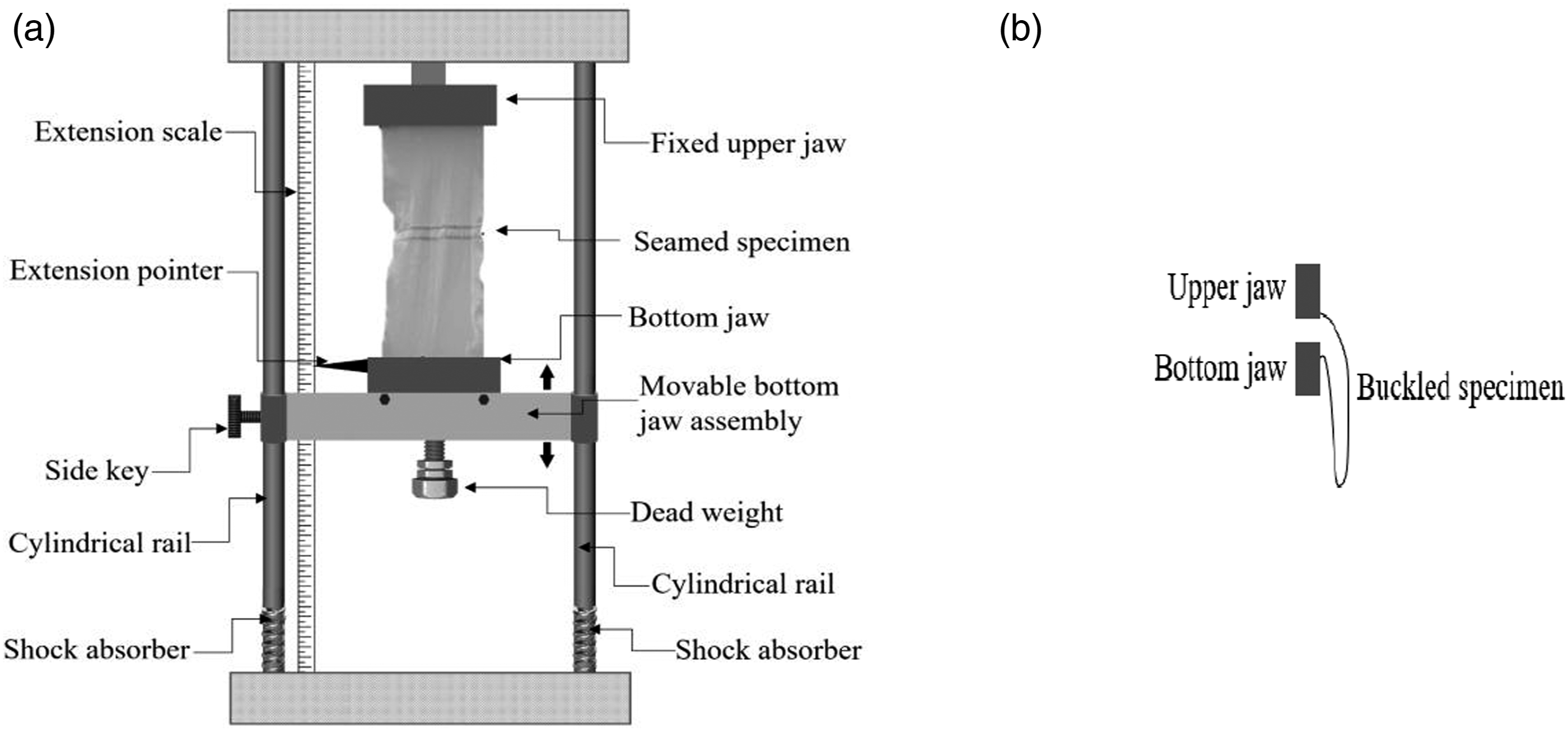
The impact tester has two gripping jaws (top and bottom) between which the test specimen is gripped by respective keys. The top jaw assembly is fixed, whereas the lower jaw assembly can be fixed (during sample mounting) or slide freely under the gravitational force (during impact testing) and is guided by a couple of fixed smooth cylindrical rails. A side key (threaded screw) at the bottom jaw is used for temporary fixing the bottom jaw close to the top jaw. At this stage specimen gripped under both the jaw will be in a buckled state (Figure 1(b)). By unlocking the side key, the bottom jaw can be released suddenly, which will exert a high impact load on the test specimen. The weight of the bottom jaw can be increased further by adding dead weights to produce a higher impact load on the test specimen. The extension scale is attached vertically to indicate extension during impact with a pointer fitted above the lower jaw.
The present impact test occurs in a fraction of a second, therefore, a high-speed digital camera (FASTCAM Mini UX-100) with 16,000 FPS is used to slow down the real-time speed and to make it easier to extract the extension of fabric with respect to small intervals of time (shown in Figure 2). Moreover, an appropriate high-speed impact load sensor can be used for the determination of additional parameters during impact. Inside high-speed camera during impact testing.
Two possibilities that may occur during present impact testing of the test specimen, given in Table 1, are whether a test specimen breaks (Case I) or does not break (Case II). The parameters that can be analysed during and after the application of impact load are listed below. 1. Study of the parameters during impact (for the first cycle and repeated cycle) • Maximum force/peak load at the time of impact (N) • Peak elongation at the time of impact (mm) • Time duration during impact (ms) • Force/elongation versus time behaviour • Force versus elongation behaviour due to impact • Peak impact speed (mm/sec) • Work done (N.mm) • Resiliency 2. Study of parameters after impact (N.mm) • Breaking strength (N) • Breaking elongation (%) • Force vs elongation behaviour due to impact • Tensile loss (%) (before and after impact) • Loss in elongation (%) (before and after impact) • Permanent set (mm) • Seam performance • Work of rupture and its loss Scheme for impact testing.

Furthermore, using current impact testing, different types of parachutes can be designed and improved in performance by analysing the aforementioned parameters. The durability of the parachute canopy can be also investigated using the Weibull distribution. 8
There are two major issues whilst following the aforementioned scheme; • Determination of Sample Dimension and Drop Height • Selection of Dead Weight
Determination of sample dimension and drop height
Determining the present sample dimension is very critical as the parachute canopy is stitched by several gores and panels,
10
mostly at 0° and 45° (Figures 3 and 4) fabric bias angles due to its higher breaking strength and elongation than other bias angles.
9
However, particularly for 45° stitched specimens, there is difficulty in testing the material in strip form. Unlike 0°, 45° stitched specimen comprises of most of the yarns remain outside of gripping jaws and not been effectively contributing to the tensile performance of the specimen; wherein the actual parachute such kind of non-contribution does not happen. Therefore, in this respect, the grab tensile test is used to overcome the uncontrolled threads (ungripped yarns within the gripping jaws) of the 45° bias angle specimen during tensile impact testing. Representation of specimen inside the parachute canopy (a) parachute canopy joined by multiple gores at 45° biased seam angle; (b) enlarged view. (a) Cutting the test specimen from the fabric at any bias angle; (b) Stitching of cut specimen in 45° bias angle; (c) Stitching of cut specimen in 0° bias angle.

Since, the impact force is influenced by the drop height (sample length) for the constant dead weight attached to the lower jaw in the impact tester, shown in Figure 1(a), that is greater drop height results in greater bottom jaw momentum (due to gravity) attached to the sample and greater impact load in the sample, and vice-versa. For widening the scope of the scheme for human dropping as well as material dropping, drop height has been increased to 300 mm. The latter value is also been taken as sample length. The width of the specimen is taken as 100 mm and the ungripped width is determined using the grab tensile testing, discussed below.
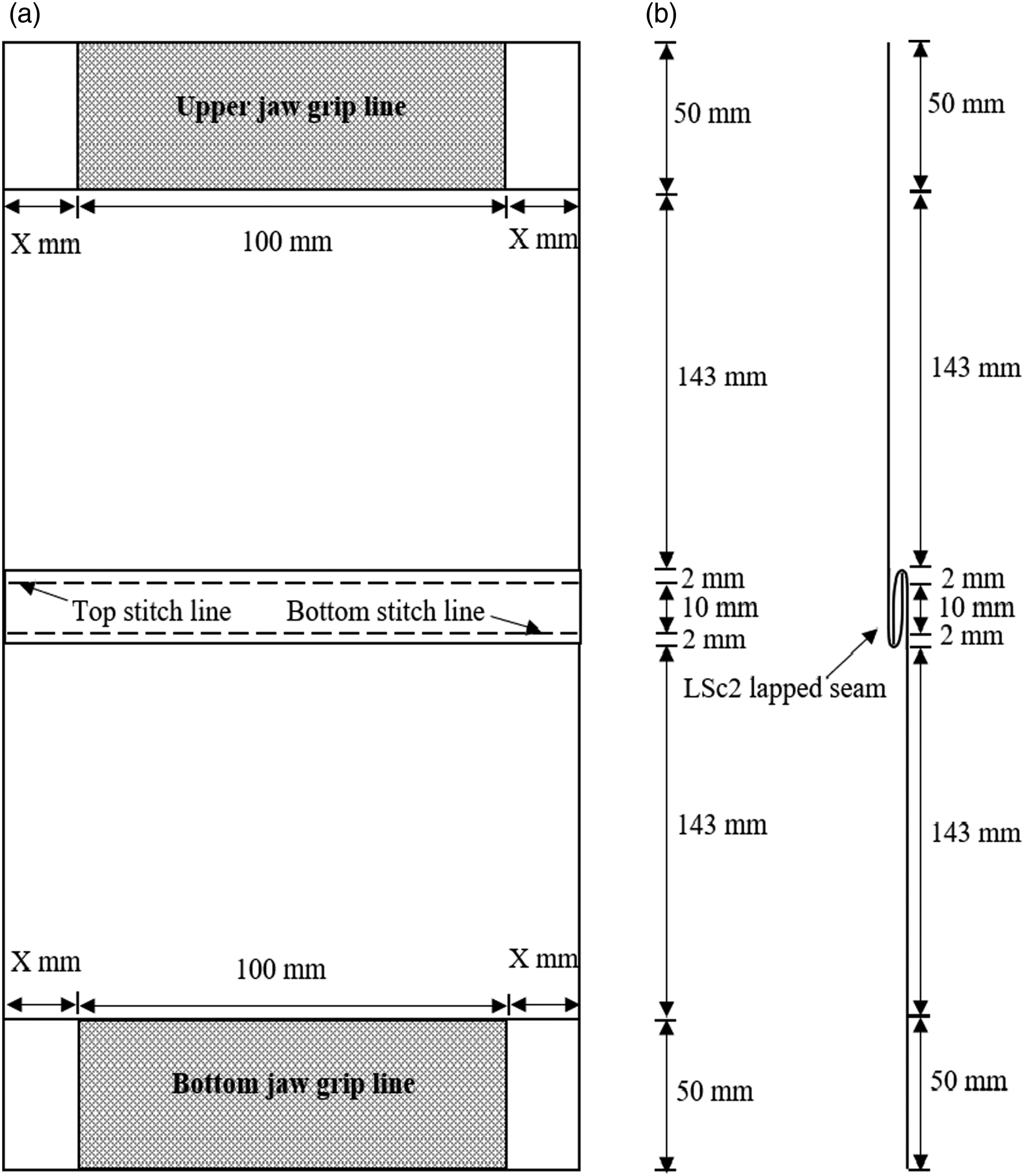
Focused on the original stitching of the typical parachute panels and gores, the present samples are cut at a fabric bias angle of 45° and stitched by LSc2 lapped seam pattern
11
considering double lock stitches with four stitches per centimetres, shown in Figure 5. The distance between the two stitch lines is kept at 10 mm (normally used in the joining of panels and gores of parachute canopy). For the grab tensile test method, the specimen is prepared as same as in the strip test but here overall width is taken as 100 mm + 2X mm, where X is the ungripped width at both the edges of the specimen. This ungripped width will counteract the adverse influence of uncontrolled yarns found in the 45° bias specimen. The details of the test specimen have been demonstrated in Figure 6. In the seamed specimen, the dimension between the jaws is kept such that the gauge length is 300 mm and 100 mm width for both the top and bottom jaw’s grip shown in Figure 6. LSc2 Seam. Strip (X = 0 mm) and grab tensile test dimension (a) for seamed specimen; (b) side view of the seamed specimen.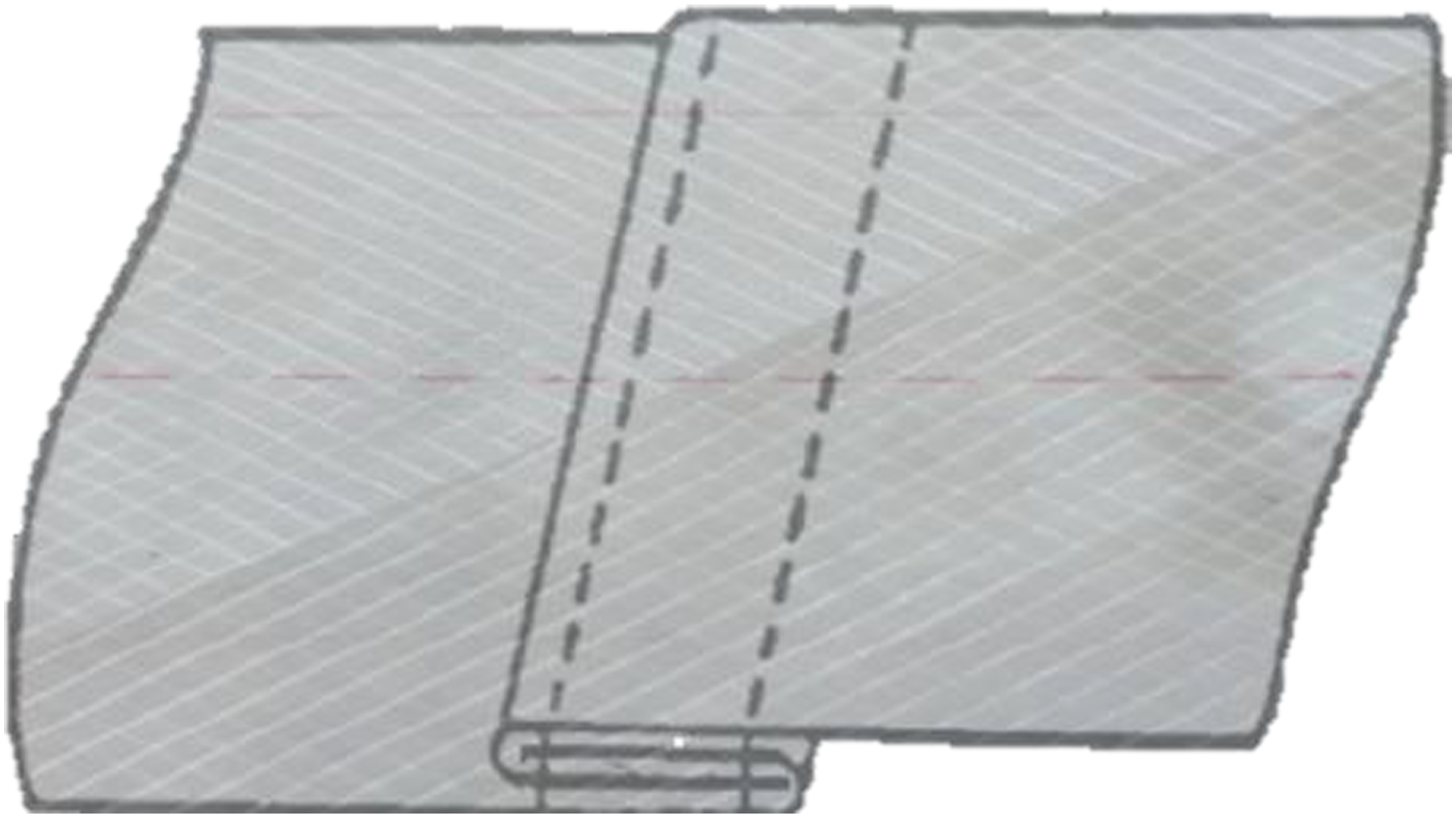
Fabric details.

Tensile characteristics of 45° bias specimen with grab tensile test.

✓’0 mm ungripped width indicates strip test’
During tensile testing of ripstop fabric, the increasing ungripped width at both the edges of the test specimen allows the rise in strength initially till the width of 20 mm, and then the variations are negligible for the specimen with a 45° angle of bias (Figure 7). This can be due to the restriction of the slippage of the threads of the system up to a certain number of crossover points, which are considerably large at the initial level. More rise in ungripped width would result in a minor difference in strength enhancement due to frictional force and using Tuckey’s test it is found that after 20 mm of ungripped width there is no significant difference between mean values of breaking strength. Based on the above observations, it is found that the most appropriate sample dimension of 300 mm (drop height and length) × 100 mm (width), and 20 mm of ungripped width is on both sides, for the tensile test and the tensile impact test. Influence of ungripped width at both the edges on breaking strength at 45° bias stitched specimen.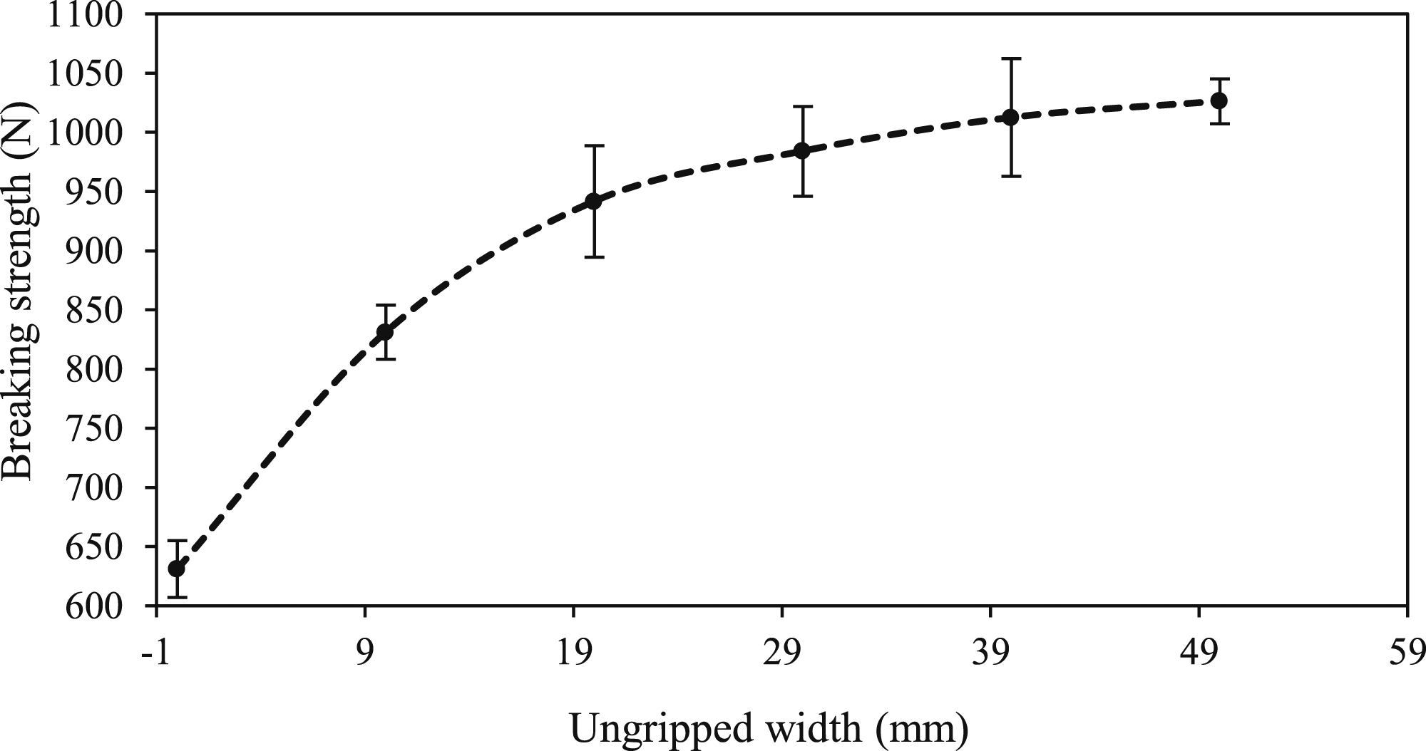
Selection of dead weight
The exact dead weight that will be equivalent to the opening force of a C-9 ripstop parachute must be determined to achieve the proper impact within the postulated specimen. It can be well reported that little variation of any of the aerodynamic properties such as altitude, the density of air, wind direction, payload, line stretch velocity or aircraft velocity, the surface area of parachute assembly, and opening time and opening angle can lead to the sharp change in opening shock force of a parachute. On the other hand, the opening shock force, cannot be computed considering all variables of different aerodynamic parameters. In the present case, the effect of change by the most influential aerodynamic variables such as line stretch velocity or aircraft velocity and payload on the maximum shock force is discussed briefly. Again, the actual payload responsible for parachute inflation has been determined via trigonometric computation in conjunction with the opening of the C-9 (flat circular) parachute.
Actual payload responsible for parachute inflation
The payload causes the parachute to descend downwards and is also responsible for the parachute inflation. Therewith, during the opening of the parachute, a larger proportion of the payload acts vertically downward (vertical component) and takes part in parachute inflation shown in Figure 8. Therefore, the geometry of the suspension lines connecting both the canopy and the payload ultimately defines the proportion of the payload used to inflate the parachute system. Actual load applied to canopy on vertically downward causing tensile impact.
Mathematically it can be calculated as follows
For a C-9 flat circular parachute canopy 12
Number of gores = 28
Suspension line length = 28 feet ≈ 8.5 m
Nominal Diameter = 28 feet ≈ 8.5 m
During inflation of parachute canopy fabric, the projected diameter is, Dp = 5.95 metre
As there are 28 no. of suspension lines, shares the total mass (m) includes the payload and parachute assembly therefore, the tension on each suspension line will be
Now, from Figure 8, Δ OAB is a right-angled triangle
So, in triangle OAB, 
Therefore, the force acting on suspension line is splitting into two components

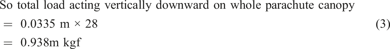
This 0.938 times the payload acts downward along the length of a gores, forcing the parachute canopy to open.
From Figure 8 it is clear that each suspension line causes vertically downward pulling due to gravitation force on the payload and simultaneously whole canopy is getting pulled upward by air-drag. Therefore, from equation (3) it can be concluded that approx. 94% of the total payload is actually responsible for parachute inflation and causing a huge opening shock force by the entire parachute assembly.
Opening shock force
The opening shock force on any flat circular parachute can be calculated 13 as,
Maximum shock force acting on the canopy,
The steady-state drag-force (Fs) of the fully opened parachute at the line stretch velocity Vs is given by,
Instantaneous shock factor
Retarded mass ratio,
And average opening time or filling time of solid flat circular parachute,
10

Height of aircraft from the sea level = 2000 m
Approximate air density at 2000-m height, ρ = 1.06 kg/m3. 14
Normal drag coefficient for flat circular parachute canopy, CD = 0.7
Surface area of opened parachute, So = 56.7678 m2
Actual weight of payload responsible for parachute inflation, W = 0.938 m kgf (from equation (3))
m: Mass of the skydiver or any light-weight droppings (payload) including parachute assembly
Acceleration due to gravity, g = 9.81 m/sec2
Constant, n = 2.5 for low porosity canopies
Opening diameter of flat circular parachute canopy, Do = 8.5 m
By putting all the above values (except payload and line stretch velocity or aircraft velocity), the maximum shock force acting on the canopy can be drawn as,
As, the present case focused on the C-9 parachute, which is a flat circular parachute, therefore, equation (9) can be used for the calculation of Fmax.
Variation of opening shock force due to change in aircraft velocity and payload
Variation in opening force of C-9 parachute considering a constant payload of 75 Kgf and variation in initial velocity of aircraft.

Variation in opening force of C-9 parachute considering a constant initial velocity of aircraft of 80 ms−1 and variation in payload.

Variation in opening force of C-9 parachute considering terminal velocity with a constant mass of skydiver of 75 kgf with respect to variation in the velocity of aircraft.

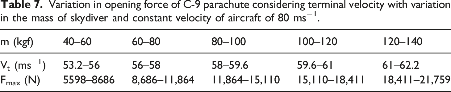
Variation in opening force of C-9 parachute considering terminal velocity with variation in the mass of skydiver and constant velocity of aircraft of 80 ms−1.
Considering initial velocity of aircraft
The initial velocity of flight or aircraft affects the opening shock force of the parachute if the parachute opens instantly just after being released from the aeroplane. Typically, this scenario occurs mainly for equipment dropping. Table 4 shows that for a constant average payload (m) of 75 kgf with increasing the parachute’s line stretch velocity (Vs) range, there will be an increment in the maximum shock force (Fmax) as the velocity component is directly proportional (from equation (9)). Table 5 shows that for a constant line stretch velocity (Vs) of the parachute of 80 ms−1 with an increasing payload (m) range, the maximum shock force (Fmax) increases as a function of the mass component. Especially when the velocity component increased the Fmax increases drastically (from Tables 4 and 5) than the increment in the mass component, this is because the Fmax is directly proportional to the square function of the velocity component.
Considering terminal velocity of skydiver
The final velocity at which acceleration becomes zero and no further increment in velocity or the maximum velocity that an object can acquire whilst falling through a fluid, such as air or water, is known as terminal velocity. 15 The terminal velocity, Vt of the skydiver is given by, 14
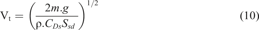
ρ: density of air
CDs: drag coefficient of skydiver during free fall
Ssd: surface area of skydiver during free fall
m: mass of the skydiver
g: acceleration due to gravity
Here, the drag coefficient of skydiver kept fixed at 0.7 and surface area calculated from the following equation.
Average surface area of skydiver, Ssd = 0.0235 m0.75. 14
Equation (10) is used to calculate the terminal velocity of the skydiver, shown in Table 6 and Table 7. In this case, instead of the aircraft’s initial velocity
In the above prediction, it is clear that when the flight velocity is too high for the constant mass of the skydiver, the lower probability of parachute failure and risk of injury if opened after reaching the skydiver’s terminal velocity, which is strongly preferred over the immediate opening of the parachute after a flight drop. If the flight velocity is between 40 and 60 ms−1 (Table 6) for a constant mass skydiver, the parachute should open immediately since there is a risk of a rise in terminal velocity, which can result in an increase in parachute opening shock force. Another significant characteristic is that parachute opening is influenced by the skydiver’s distance from the ground, therefore terminal velocity is not always the deciding factor for opening shock force.
Estimation of dead weight
The current small-scale impact testing is the most significant aspect of parachute performance assessment. Also, the dead weight (md) selection is the essential part of the present study and for the current sample, the md must be predicted based on changes in Fmax (from equation (9)) of the entire parachute canopy and the proportionate impact load on the present sample, the width of 100 mm (Fw).
Since Fmax is shared through whole canopy circumference, the required equivalent stress on unit width and present specimen width can be calculated as follows. Using equation (9), stress on specimen per unit width can be expressed,
16
which is equal to 

(As for C-9 parachute Do is 8.5 m)
For present research the width of the specimen gripped by the jaw is 100 mm, therefore, stress on the specimen of 100 mm width considering safety factors 20%,
By putting equation (9) in equation (13), 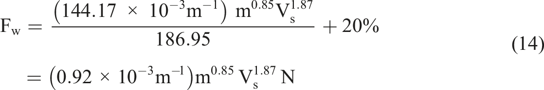
Equation (14) is used to calculate the proportionate impact load is to be applied on present sample. The calculation of dead weight (md) is explained below.
Since changes in dead weight will change the impact force on a particular fabric so, the impact test is performed for stitched ripstop parachute fabric (details are given in Table 2) using an impact tester (Figure 1), to assess the impact force for different dead weights. The minimum weight of the lower jaw is 3 kg, and the impact test is performed for stitched ripstop fabric with an incremental dead weight of 500 gm (3, 3.5 and 4 kgf), considering three replicas for each. During impact testing, the extension of fabric in small intervals with respect to the short period of time is recorded easily by a high-speed digital camera, shown in Figure 2. When the lower jaw is released in the tensile impact tester (Figure 1), it moves smoothly with acceleration due to gravity, and once the fabric specimen begins to stretch, the speed of the lower jaw started to decline, causing deceleration. Here, the peak deceleration is greater than the acceleration due to gravity because of the change in momentum, which induces a high impact force. The peak deceleration is measured based on extension of fabric with respect to time factors.
We know that,
In present case the peak impact load can be considered as Fw for dead weight calculation so, dead weight will be,
To predict the dead weights for application of proportionate impact load on the postulated sample based on different ranges of opening shock force in parachutes, the following regression equation (equation (17)) is generated in connection with variation in deceleration with respect to dead weights (Figure 9). As regression equation possesses a high level of r2 value (r2 = 0.98) and lower level of SE (3.3) indicate that it is quite appropriate for the predictability. Therefore, it is used to find out an approximate opening shock force for given range of dead weight and vice-versa. It may be noted that textile materials are viscoelastic (change of tensile properties is not proportional with the load) and further due to extrapolation, some error is inevitable. However, evaluation of approximate dead weights corresponding to opening shock forces can provide us the guideline for testing the materials. Curve between deadweight and deceleration of ripstop fabric.
The following regression equation (r2 = 0.98; SE = 3.3) has been fitted with the aforementioned trend. r2 value is the coefficient of determination, used to indicate the goodness of fit of the regression model. Whereas, the range of the mean of the experimented values can be evaluated using Standard error (SE).
Where, Y = deceleration and X = dead weight
Different opening shock force ranges with the mode of dropping for the C-9 parachute.
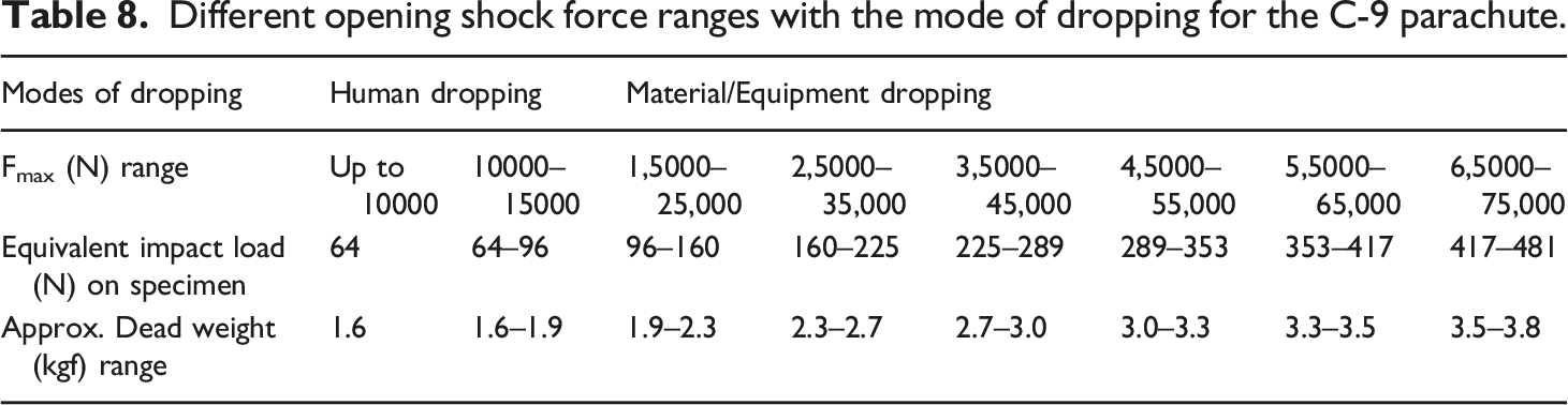
Since the human tolerance limit for the opening shock force varies according to a person’s physiological characteristics. The maximum tolerance limit for a female pilot is 5.2 ± 0.6 G (‘G’ is the multiples of earth gravitational acceleration), 17 whereas the United States Air Force School of Aerospace Medicine (USAFSAM) reports that man can tolerate +9 G for 45 s and +8 G for 60 s. 18 Research has estimated that military parachutists can undergo accelerations ranging from 5 to 15 G. 19 It is also expected that wearing an anti-G suit will increase tolerance up to +5 G. 20 Therefore, it can be concluded that a skydiver can tolerate up to 15 ± 5 G (1125 ± 375 kgf, considering the average weight of parachutists is 75 kgf) opening shock force whilst wearing an anti-G suit; however, beyond (1125 ± 375 kgf ≈ 11,036 ± 3679 N) that, for C-9 parachute the light-weight material or equipment should be dropped to avoid severe injuries to the skydivers. Based on these discussions, the mode of dropping such as human dropping and materials dropping is reported in Table 8. Again, materials or equipment should be dropped with keeping the maximum impact strength of the specific parachute in mind to avoid failure.
Case study
Materials
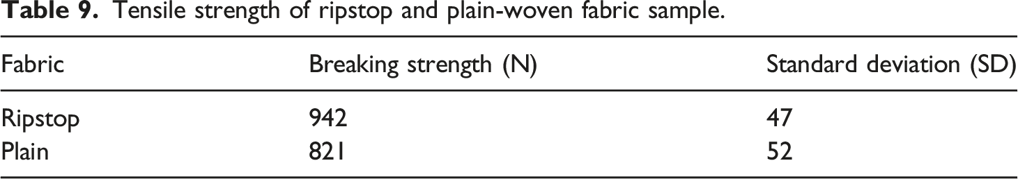
The square ripstop and plain-woven nylon fabrics are selected for the present study. Basic geometrical and stitched construction of actual fabrics are shown in Figures 10 and 11. The details of the fabrics are given in Table 2. For stitching, three plied Nylon 66 sewing thread having an overall linear density of 84 tex has been selected. The average breaking strength of the sewing thread is 35 N. (a) Geometrical; (b) stitched construction of ripstop fabric. (a) Geometrical; (b) stitched construction of plain-woven fabric.

Results and discussion
The characteristics of the fabric sample at the time of impact is a very important consideration in small-scale impact testing and this has been tested with a tensile impact tester, shown in Figure 1(a). Therefore, different properties of ripstop and plain-woven fabric specimens are studied and described further below.
The impact duration (is the very short time duration between the velocity of lower jaw changes from highest value to lowest or zero) has been measured using a high-speed digital camera (Figure 2) for ripstop and plain-woven fabrics with different dead weights (3, 3.5 and 4 kgf), shown in Figure 12(a). Impact duration increases with dead weight for both fabric samples, however, there is a significant difference between ripstop and plain-woven fabrics. In this case, the plain-woven fabric exhibits a higher impact duration than ripstop fabric. Effect of deadweight on (a) impact duration; (b) impact load on the specimen; (c) opening shock force on the parachute canopy, by ripstop and plain-woven fabrics.
Furthermore, using high-speed digital videography, the peak impact forces for the dead weight of 3, 3.5 and 4 kgf are extracted, shown in Figure 12(b). In this case, the different dead weights produce different impact loads (ranges from 275 to 545 N approx.) on the specimen constructed by ripstop and plain-woven fabrics, which corresponds to different levels of opening shock force (ranges from 43,000 to 85,000 N approx.) experienced by a C-9 parachute canopy, shown in Figure 12(c). It is clear that if the dead weight for impact testing increases, the impact load on the specimen and the corresponding equivalent opening shock force on the parachute canopy will increase. It is due to higher mass leading to higher change in momentum during impact. 21 Although the curve inclination is nearly the same in Figure 12(b) and (c) but, the curves of ripstop and plain-woven fabrics are significantly different, and the difference increases with the dead weight.
Following the working principles of the impact tester (Figure 1(a)), when the lower jaw is released, it moves downward under gravitational acceleration and reaches maximum velocity before the specimen begins to extend. Thereafter, the velocity of the lower jaw starts to decline and eventually approaches zero after the specimen has reached its maximum extension, which will vary depending on the dead weight, fibre type and constructional variability of the fabric.
From Figure 12(a)), plain-woven fabric specimens have a longer impact duration so, it produces a lower impact load and will produce lower equivalent opening shock force on the parachute canopy than ripstop fabric specimens. It is because the force (impact load) is inversely proportional to the time component for a constant mass (m) and velocity (v), given in the equation (18). 21
Mathematically,
In the present case, the change in velocity for different dead weights is same as the drop height (i.e. 300 mm) is identical and the final velocity is zero. Again, using a high-speed digital camera, the load versus extension curve is drawn for ripstop and plain-woven fabric samples for the dead weight of 3, 3.5 and 4 kgf, as shown in Figure 13. From the curve, it is clear that all the curve follows the exponential growth as the fabrics belong to viscoelastic materials and have a maximum extension before reach into maximum force. In each particular interval, the extra thicker yarns are present in the ripstop fabric (Figure 10), restricting the extension of the fabric up to some extent than plain-woven fabric also due to lower impact duration (Figure 12(a)), causing lower extension than plain-woven fabric. Therefore, considering impact duration and extension during impact, the ripstop fabric produces a higher impact force than plain-woven fabric. The 4 kgf dead weight produces maximum impact load with extension than 3 and 3.5 kgf dead weights and in both cases of fabrics, the load increases with increase in dead weight. It is because the higher mass would extend the specimen faster than lower mass, or the change in momentum for higher mass is greater, resulting in maximum deceleration.
21
There is no statistical difference at lower loads of all curves due to similar materials (both fabrics are following the similar construction and made of nylon fibre) gives an almost similar response to lower loads and lower extension. But at higher loads, there is a statistically significant between ripstop and plain-woven fabrics due to structural differences and difference in yarn count with densities. Load vs extension curve for ripstop and plain-woven fabric during impact for the dead weight of (a) 3 kgf; (b) 3.5 kgf; (c) 4 kgf.
In order to calculate the total work done by the fabric samples during impact by the three different dead weights, the area under the curve from Figure 13 is used. It is found that the response of the two different fabrics towards impact load is different in terms of extension, shown in Figure 13. However, there is no statistically significant work done between ripstop and plain-woven fabric, shown in Figure 14. Since the plain-woven fabric extends more and at the same time absorbs more impact force during impact load than ripstop fabric so, there is a similar level of work done by ripstop and plain-woven fabrics. As ripstop fabric woven with a double or extra thick thread at regular intervals (Figure 10), creating a pattern of small squares,
1
which resisting loads and also produce slightly lesser extension than plain-woven fabric at the time of tensile impact. Effect of dead weight on work done by ripstop and plain-woven fabric.
Tensile strength of ripstop and plain-woven fabric sample.
Conclusion
The performance of small rectangular stitched parachute canopy fabric under tensile impact is an important consideration to characterise the entire parachute canopy. This simple testing can help in designing and development of parachutes. The drop height for tensile impact has been set at 300 mm to broaden the testing scheme, and the rectangular stitched sample dimensions, length of 300 mm and width of 100 mm is selected. The orientation of yarns in the present stitched specimen at 45° fabric bias angle is not along the direction of impact testing and not comes inside the gripping zones of both the jaws, and can affect the results. Therefore, to avoid the error in results the ungripped width is taken as 20 mm, which is determined through the grab test. Furthermore, the actual payload responsible for parachute inflation has been discussed. If the parachute opens immediately after being released from the aeroplane, the entire parachute will experience a higher opening shock force than if it opened after achieving terminal velocity. The approximate dead weight ranges are predicted for the application of equivalent force on the current rectangular stitched sample, considering different ranges of parachute opening shock force. The deceleration is the important aspect when calculating the equivalent deadweight for any kind of impact testing and for the measurement of that, a high-speed digital camera or impact load sensor can be used. The type of parachute payload can be determined by opening shock force ranges concerning aerodynamic variations and human tolerance limit. The impact duration and load versus extension curve during impact under different loads indicates that for human dropping, the plain-woven fabric is preferable due to its higher extension and impact duration than ripstop fabric. This will result lower level of shock force in the entire parachute canopy, which will be transferred to the skydivers. Ripstop fabric on the other hand can be used for any kind of materials dropping as in that case higher strength is more important.
Footnotes
Declaration of conflicting interests
The author(s) declared no potential conflicts of interest with respect to the research, authorship, and/or publication of this article.
Funding
The author(s) received no financial support for the research, authorship, and/or publication of this article.