
Abstract
This study embodies evaluation of ideal test specimen dimension for the study of tensile characteristics of lapped seam parachute canopy fabric. Due to anisotropic nature of textile fabrics, the mechanical property of unseamed and seamed fabric changes with the change in specimen test direction. Therefore, measurement of tensile property at different bias angle (an acute angle between warp and specimen length/test direction) becomes more important in parachute canopy where joining of its various parts is not only in principle direction but also at different bias angle. The present paper deals with the influence of bias angle of stitching on breaking strength and elongation of unseamed and lapped seam parachute canopy fabric using test specimen dimension based on previous practice. Present study reveals that there is need of re-specification of specimen dimension for evaluation of tensile properties of parachute fabric. With the changes in angle of bias, width and gauge length of test specimen, the number of different category of warp and weft yarns available between the specimen grip lines changes and can be calculated mathematically. This has important role in affecting the ultimate properties of parachute fabric. Based on the study, an optimized dimension of test specimen has been postulated for evaluation of tensile characteristics of parallel/opposite stitched specimen through which reliable test result can be obtained. The proposed dimension can be used for comparative analysis of breaking strength and elongation of unseamed and seamed fabric at different bias angle.
Background
The anisotropic nature of textile fabrics affects the mechanical property of unseamed and seamed fabric with the change in specimen test direction [1–5]. Therefore, tensile properties of fabrics along various directions besides principle direction are very important in many technical textiles like in parachute, military garments, body armour, air bags etc., where joining of parts are not only along principle direction but also at different bias angle [1–2,6–10]. While considering parachute, during opening, it experiences high shock force and this shock force is shared through canopy fabric, stitches and seams, webbing and suspension line of parachute system. Failure of parachute could be fatal; even if failure does not occur, performance of parachute continuously degrades due to dynamic pressure acting on its various components after opening. Besides the quality of fabric, quality of seams and stitches are very important for effective performance of parachute [11–13].
For designing a parachute with high drag area, parachute canopy with a large surface area is required and this large parachute canopy is constructed by joining a number of panels and gores through stitches and seams. However, there are two different ways of canopy construction either block or bias. In block construction, warps are kept parallel to the hemline (the bottom edge of parachute skirt) of parachute, while in bias construction, it is placed at 45° to the hemline, which has been shown in Figure 1 [11,12]. In these constructions, the seam angle (an acute angle made between the warp and seam direction) varies with the change of number of gores (as shown in Figure 1 and mentioned in Table 1). Seam angle is directly related with fabric bias angle (as shown in Figure 2(a) and mentioned in Table 2) which is an acute angle made between the direction of specimen length and its warp. The said parameter is important to measure the effect of bias angles on the tensile characteristics of unseamed and seamed fabric to compare the tensile behaviour of different parachute canopy joined at different seam angle.
(a) Joining direction of panels and gores in block construction; (b) Joining direction of panels and gores in bias construction; (c) Depiction of seam angle in block construction; and (d) Depiction of seam angle in bias construction. (a) Cutting the test specimen from the fabric at any bias angle; (b) Stitching of cut specimen in parallel direction; and (c) Stitching of cut specimen in opposite direction. Calculation of seam angle with the change of number of gores in block and bias constructed parachute. Calculation of seam angles with respect to fabric bias angle.


Further during formation of parachute canopy, fabric components are generally joined in two different manners – either keeping the two components parallel, i.e. keeping the alignment of warp and weft yarns in same direction or keeping the two components opposite, i.e. keeping the alignment of warp and weft yarns in opposite direction as shown in Figure 2(b) and (c), respectively.
Figure 1 shows that in case of block construction, both panels and gores are joined in parallel, but in bias construction, any two panels of same gores are joined in parallel but any two gores are joined oppositely [11,12]. Although the seams are used for making large construction by stitching a number of fabric components, but the primary function of seam is to provide uniform stress transfer from one piece of materials to another and to preserves the overall integrity of the assembly [14]. The basic performance properties of stitches and seams include strength, elasticity, durability and security. In use, a seam may be loaded at any angle to the direction of sewing and the responses of seam vary both with direction of loading and size of load. Further seam failure has been divided into two types: Type I, in which only the sewing thread breaks without damaging the fabric; and Type II, in which only the fabric breaks without damage to the sewing thread [2].
There are much work related to seam tensile characteristics and out of which most of these are based on studies related to the effect of fabric type, sewing threads, gauge length, stitch density, stitching speed, methods of testing (Strip and Grab test), etc on seam strength, seam elongation and seam slippage [14,15–19], but the work related to impact of seam angle in relation to fabric which is most important in case of parachute is very limited. In the recent past, some researchers work on the measurement of seam strength and elongation at different bias angle using superimposed lock stitch seams [1,20,21]. All such studies support that the plain square fabric sewn at 45° bias angle has almost same strength as at 0° and 90°, which is also higher among other bias angles. It is to be added that the type of seam also influences the tensile characteristics of sewn fabric [22], but the above-mentioned studies are mainly restricted to superimposed seam (basic seam used in joining of various parts of many garments). Among vast range of seams [23], lapped seams (as shown in Figure 3) are most important while considering the joining of panels and gores of parachute canopy.
Schematic diagrams of (a) superimposed and (b) lapped seam.
Seam efficiency of lapped seam parachute fabric only in orthogonal and 45° bias direction was measured earlier by Coplan and Bloch and concluded that the 45° bias angle gives highest seam efficiency [20]. It may be added that the above study was based on steady state tensile testing; although in real application, parachute fabric is exposed to impact loading. It is important to note that joining of parachute canopy is normally accomplished in various other directions than studied by Coplan and Bloch [20]. It is therefore important to study the impact of bias angle of stitching more thoroughly on the breaking strength and elongation of seamed/unseamed materials. Besides the above aspects, there are no test standards regarding specimen size that have been reported till date for the measurement of seam strength at different bias angle. Therefore, as a starting point, the test specimen dimension used by earlier researchers [20] has been selected for the present study. The present paper deals with the study about influence of various bias angle of stitching (keeping two fabric components are parallel) on the tensile characteristics (mainly breaking strength and breaking elongation) of unseamed and lapped seam parachute fabric. Further an optimised specimen dimension has been postulated for proper comparative analysis of tensile characteristics of unseamed and seamed fabric. The present study is helpful in two ways; firstly, adhering to most appropriate sample dimension for testing and evaluation of seamed and unseamed fabrics which is in turn is useful for design and development of parachute, secondly, joining of gores and panels in parachute fabric can be standardised so as to achieve requisite tensile strength and elongation.
Experimental
Materials
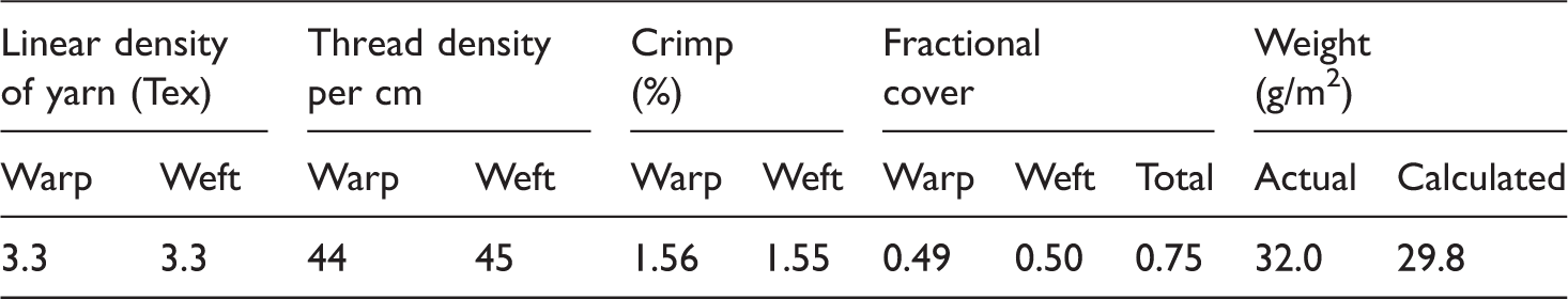
Material details.
Methods
As mentioned earlier, the measurement of breaking strength and elongation of unseamed and seamed fabric at different bias angle is started based on sample dimension used by earlier researchers [20]. Test specimens for the seamed and unseamed fabric have been prepared as per the dimension shown in Figure 4(a)–(c), respectively.
(a) Sample dimension of lapped seam fabric used by Coplan and Bloch [20]; (b) Sectional view of sample; and (c) Dimension of test samples for the tensile test of unseamed fabric.
For sample preparation of seamed specimen, a fabric of dimension 258 mm length (including 114 mm gauge length, a total of 44 mm for folded part of lap formation and 100 mm length for both top and bottom jaw’s grip) and 100 mm width is selected at different bias angle. This fabric sample is then cut from middle across the length and then joined parallel (according to pattern in Figure 2(b)) by using LSC2 lapped seam with four stitches per cm. The distance between the two stitch lines is kept at 10 mm (normally used in the joining of panels and gores of parachute canopy). Total four slits of each 25 mm in length are then made in the fabric both sides of seam line. As the straight part of seamed specimen actually has 214 mm length (Figure 4(a)) therefore dimension for unseamed fabric was taken as 214 mm in length (including 114 mm gauge length and a total of 100 mm length for both top and bottom jaw’s grip) and 50 mm width (Figure 4(c)).
After sample preparation, the measurement of breaking strength and elongation of both unseamed and seamed fabric at different bias angles is carried through mounting the specimens between the jaws of 80 mm width and 50 mm height at CRE-based tensile tester followed by extending the specimen at a constant speed of 300 mm/min. For each bias angle, 10 tests are conducted and the average values of tensile strength and elongation and their standard deviation are computed. The experiment was conducted in standard atmospheric condition of 20° ± 2℃ temperature and 65% ± 2% relative humidity. Before the tensile test, all the samples were conditioned for 24 h in standard atmospheric conditions. The test results obtained have been compared statistically using t statistics. For the measurement of seam efficiency, following equation has been used:
Schematic diagram showing propagation of breakage through slit line at 15°.

The reason for such breakages through slit line has been thoroughly analysed and found that:
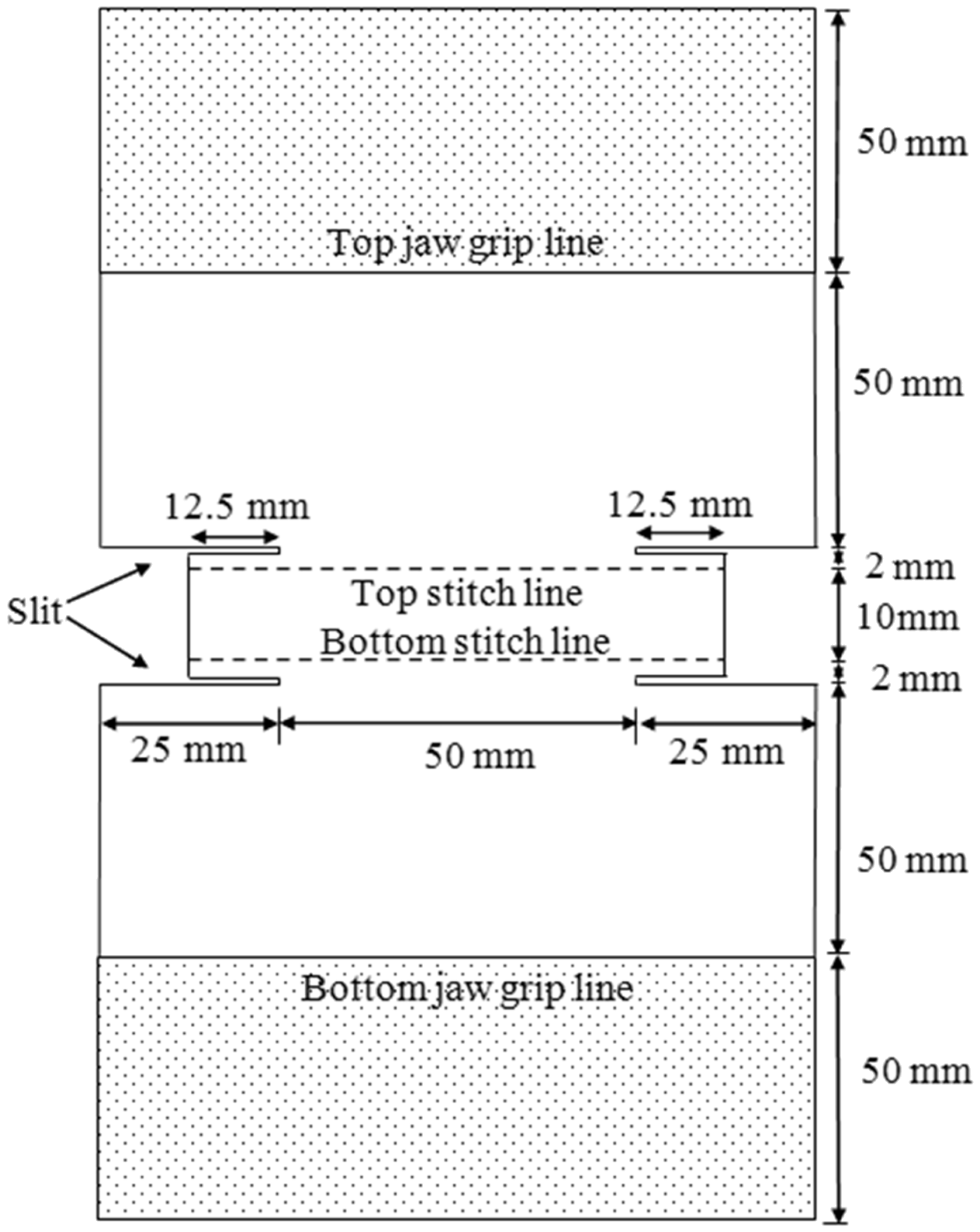
At the bias angle other than 45°, the orientation of warp and weft yarns inside the specimen was asymmetric (as shown in Figure 6). Due to the above, there will be load imbalance between warp and weft; that means one group of thread will reach breaking point earlier than the other group. This will results in less overall strength of the material. In addition, as compared to 0°/90° of joining, there is increase in total number of yarns which are gripped by only top/bottom jaw. Due to this, some portion of yarns of the aforementioned group which also posses’ inadequate crossover points (interaction among warp and weft) started to slip out from the edge of the specimen before breakages and results in fall in breaking strength and elongation. Another reason for such early breakages is attributed to the weight of four-layered stitched fabric which hangs freely on both sides of edges in between two slit lines. It tends to increase stress concentration at the edges.Therefore, to avoid such unacceptable breakage through slit lines, the aforementioned two factors must be controlled. The first factor can be controlled by changing the sample dimension. While controlling the second factor, it has been noticed that by reducing the projected length of layered fabric to 12.5 mm (modified sample is shown in Figure 7); the likelihood of breakage at the slit gets substantially reduced. Increasing order of symmetric yarn orientation in the specimen with respect to tensile test direction when bias angle changes from 0° to 45° (a) Perfectly asymmetric orientation of warp and weft yarns at 0°; (b) Correspondingly more symmetric orientation of yarns at 15°; (c) perfectly symmetric orientation of yarns at 45°. Modified dimension of lapped seam specimen.

Above study indicate that there is need to idealise the sample dimension. However, in the beginning to study the ultimate properties of the seamed/unseamed fabric, specimens are prepared by controlling the second factor only but its dimension is kept in accordance to Coplan and Bloch [20] to adjudge its suitability for the same.
Results and Discussion
Breaking strength and breaking elongation of seamed and unseamed fabric.
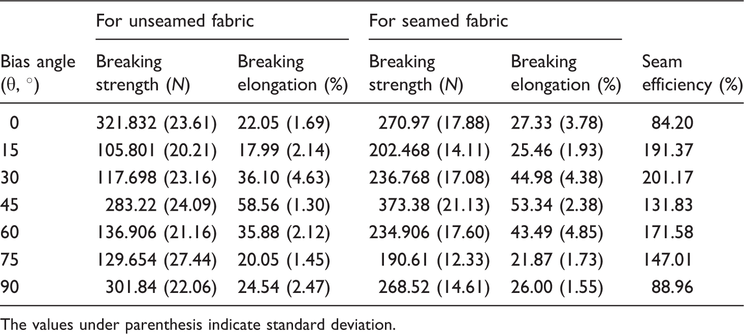
The values under parenthesis indicate standard deviation.
In present case, these parameters are mainly influenced by bias angle as it not only changes the orientation of yarns inside the specimen but also the number of different category of warp and weft yarns (as mentioned in Tables 5 and 6) and other associated parameters. The type of different category of yarn can be grouped as follows;
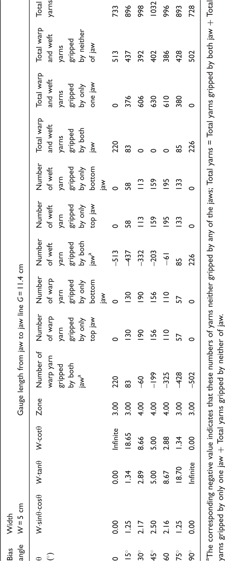
Warp and weft yarns which are gripped by both jaws Warp and weft yarns which are gripped by only one jaw (top or bottom in case of unseamed fabric) or (top or bottom or pseudo jaw in case of seamed fabric) Warp and weft yarns which are gripped by neither of the jaws Number of different category of yarns available between the top and bottom jaw at different bias angle in unseamed fabric specimen. aThe corresponding negative value indicates that these numbers of yarns neither gripped by any of the jaws; Total yarns = Total yarns gripped by both jaw + Total yarns gripped by only one jaw + Total yarns gripped by neither of jaw. Number of different category of yarns available between the jaw and seam line (pseudo jaw) at different bias angle in lapped seam fabric specimen. aThe corresponding negative value indicates that these numbers of yarns neither gripped by any of the jaws; Total yarns = Total yarns gripped by both jaw + Total yarns gripped by only one jaw + Total yarns gripped by neither of jaw. The number of different category of yarns available between the top jaw and first seam line (pseudo jaw) from top of specimen is same to that of available between the bottom jaw and first seam line from bottom of the specimen. Different category of warp and weft yarns available between the jaws.
Figure 8 illustrate how different categories of yarn in between the top and bottom jaws (in case of unseamed fabric) or between any of jaw and seamline (in case of seamed fabric) changes with the change in bias angle. Based on experimental observations, it was found that the seam line also participates in influencing the tensile characteristics of seamed fabric. In case of seamed fabric, the seam line acts as a pseudo jaw and grips some of those yarns which are unable to grip between the top and bottom jaw of unseamed fabric. The details of influence of bias angle on breaking strength and elongation of unseamed and seamed specimen have been discussed in the following sections.


Effect of bias angle on tensile characteristics of unseamed fabric
The trend of change in tensile strength and elongation of unseamed fabric with the change of bias angles can be observed from Figure 9. When the bias angle is at 0°, all warp yarns oriented vertically and gripped by both the jaw while all the weft yarns remains parallel to jaw width. Breaking strength and elongation in this region is contributed mainly by warp yarns, the number of interlacement points made by warp and weft yarns and corresponding frictional and contact force between the yarns. In this case, the breakage of specimen occurs between the jaws (Figure 10(a)).
Breaking strength and breaking elongation of unseamed fabric. Breakage pattern of unseamed fabric after tensile test at two different bias angle (a) 0° and (b) 15°.

With the increase in bias angle from 0° to 45°, there is an increase in breaking strength and elongation of fabric except 0° to 15°. In this region, the characteristics of specimen are mainly governed by asymmetric orientation of warp and weft yarns (as shown in Figure 6). Due to the above, there will be load imbalance between warp and weft; that means one group of thread will be reaching breaking point earlier than the other group. This will results in less overall strength of the material. It can be also observed from Table 5 that with the increase in bias angle, in spite of increase in total number of yarns gripped by top/bottom jaw, numbers of unsupported threads are also increasing. The latter group of thread laying parallel close to the edge; this leads to unsupported edged yarns tend to slip out during loading. This leads to breakage of specimen nearer to jaws (Figure 10(b)).
With further increase in bias angle from 15°, the orientation of the yarns also approaches towards symmetry which reduces the influence of load imbalance and warp–weft yarns that starts to support each other in load sharing. In addition to this, the increasing trend of total numbers of yarns participating in tensile strength (as shown in Table 5) starts dominating in this region and contributes in enhancement of ultimate tensile property of the specimen. It may be added that constituent yarns which are not gripped by both the jaws are also supported by crossover points; therefore they contribute in ultimate properties of the material. This causes increase in both breaking strength and elongation. But the increase in strength is not as significant as compared to elongation because of reduction in total number of yarns gripped by both the jaws (as shown in Table 5). At 45° bias angle, although the total number of yarns gripped by both the jaws becomes zero (as shown in Table 5), but still high strength and elongation are observed mainly because of enhancement in higher number of warp–weft interlacement points and complete symmetric orientation of warp–weft yarns inside specimen. In addition to this while applying tensile load, shear force acting between warp–weft also tend to modify fabric strength and elongation. Due to yarn alignment, breaking elongation tends to be higher at 45°. However, it is noticed that breakage of the specimen at 30° and 45° bias angle eventually take place nearer to the jaws as like in 15°. When the bias angle further increases from 45° to 90°, the resulting trend of tensile strength and elongation is almost symmetric to 45° because of the square plain structure of selected parachute fabric.
Effect of bias angle on tensile characteristics of seamed fabric
The trend of change in tensile strength and elongation of seamed fabric with the change of bias angles can be observed from Figure 11 which is similar to that of unseamed fabric and have similar explanation as discussed in case of unseamed fabric. However, it is noticed that breaking strength (except at 0° and 90°) and breaking elongation of seamed fabric are more as compared to unseamed fabric.
Breaking strength and breaking elongation of seamed fabric.
It can be explained as free yarns (gripped by either of the jaw) are also anchored by additional binding points at the seam line. As mentioned earlier that the seam line can be conceived as pseudo jaw that restricts the movement of aforementioned free yarn to slip out during tensile test of specimen. It is to be noted that such free yarns are not present in case of bias angle of 0° and 90°. It is seen that unlike unseamed specimen, breakage of seamed sample was mainly observed nearer to seam line (as shown in Figure 12).
Breakage pattern of seamed fabric after tensile test at two different bias angle (a) 0° and (b) 15°.
From the above results and discussion, it is clear that the bias angle affects the tensile properties of both unseamed and seamed fabric in similar manner. However, the use of present specimen dimension is appeared to be inadequate in measuring the breaking strength and elongation of seamed fabric. Primarily, it fails in comparing the results with the tensile results of unseamed fabric tested at equivalent width and gauge length. Table 4 shows that except at 0° and 90° of bias angle, the seam efficiency value is inflated as it shows more than 100%, which is a wrong indicator. In actual, the seam efficiency always remains below 100%. In present case, more than 100% seam efficiency is observed mainly because of the underestimation of fabric strength due to inappropriate ratio of specimen gauge length and width. Therefore, it is necessary to optimise the specimen dimensions mathematically to obtained reliable results so that one can compare the tensile characteristics of seamed and unseamed fabric accurately. In the proposed dimension, slipping out tendency of yarns can be suppressed by optimising the selection of gauge length and width of the test specimen so that both unseamed and seamed specimen will have minimum number of uncontrolled yarns.
Optimisation of sample size
It was analysed that, while increasing the gauge length for constant width of specimen, number of different category of yarns available between the top and bottom jaws (in case of unseamed specimen) or between the top or bottom jaw and seam line (in case of seamed specimen) changes. The change in the number of these yarns also varies with bias angle. For a constant width and bias angle, if the gauge length increases, the number of yarns gripped by both the jaws (in case of unseamed specimen) or by the jaw and seam line (in case of seamed specimen) decreases.
Optimised sample size should be derived in such a manner so as to minimise uncontrolled yarn in fabric during testing at all bias angle excluding 0° and 90°. A mathematical relationship has been developed which can relate the gauge length, fabric width and bias angle to measure the number of different category of warp and weft yarns available between the jaws or in between the jaw and seam line depending upon unseamed and seamed specimen so that one can select the optimum dimension where number of uncontrolled yarns remain minimum to provide accurate tensile results that can be used in comparing the tensile characteristics of unseamed and seamed specimen at different bias angle.
In the Figure 13, ABLKA is a rectangular piece of fabric specimen in which warp has been placed parallel to line AJ at bias angle θ. The solid line AJ and dotted line BF represent one of the warp and weft yarns of the fabric specimen, respectively which is perpendicular to each other. The whole specimen can be segmented in four different zones (I, II, III, and IV) based on location of top and bottom jaws. This will influence the yarns gripped by both the jaws, either of the jaws and not being gripped by any jaws. The performance of the material will be largely influenced by the presence of different category of yarns in the tested specimen. Moving from Zone I to IV will signify more number of uncontrolled yarns with respect to jaw. However, control of yarn will still persist due to interaction at crossover points. During tensile test, the line AB considered as top grip line, but for the bottom grip, any other line parallel to AB can be selected across the fabric from any of the segmented four zones as shown in Figure 13. Depending upon the selection of bottom grip line, the number of different category of yarns available between the grips varies which in turn changes the tensile characteristics of the specimen. The details of how the number of such yarns changes in these zones have been mathematically analysed for the bias angle from 0° to 45° with respect to warp and described as follows.
Different possible gripping zones in bias cut fabric specimen.
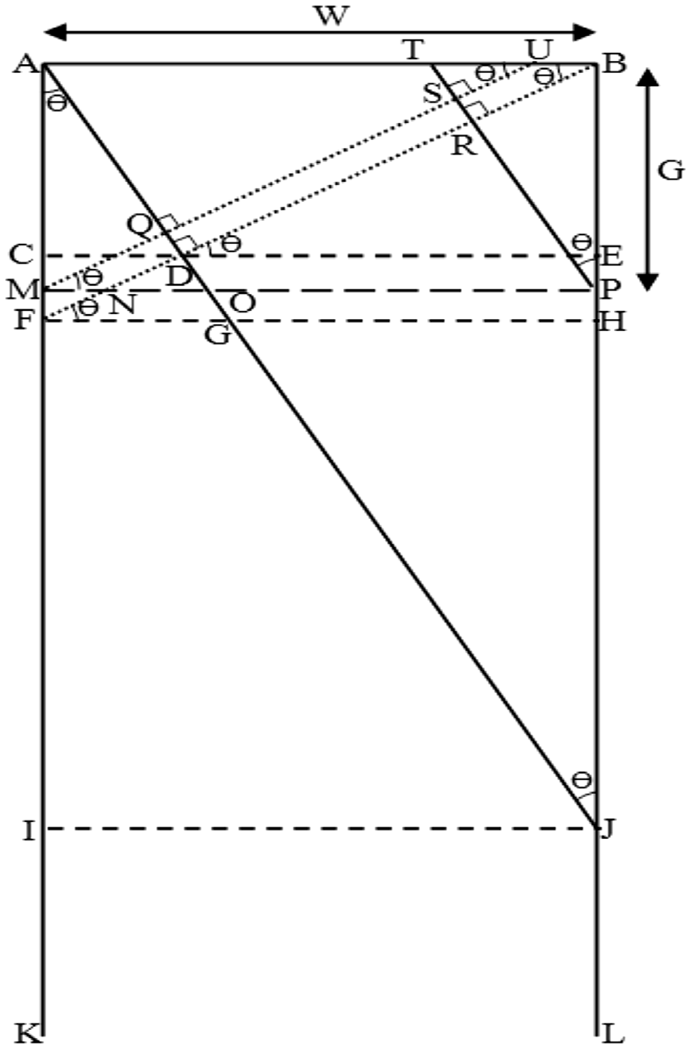
Zone I: Figure 14 shows the bottom gripping position of fabric specimen inside Zone I. Here, ABPMA represents the dimension of test specimen. The straight lines AB and MP represent gripping line of top and bottom jaw, respectively. The solid lines AN and SP represent the two warp yarns while dotted lines MR and OB represent the two weft yarn of test specimen.
Gripping position of fabric specimen in first zone.
Other warp and weft yarns of specimen are placed parallel to AN and MR, respectively. In this zone, the number of warp and weft yarns gripped by top and bottom jaw at different bias angle can be calculated by using below derived formula:
No. of warp yarn gripped by both jaw = n1(DT) = n1(DB − TB) = n1 (AB·cosθ − PB·sinθ) = n1(W·cosθ − G·sinθ) No. of warp yarn gripped by top jaw = n1(TB) = n1(PB·sinθ) = n1(G·sinθ) No. of warp yarn gripped by bottom jaw = n1(MQ) =n1(AM·sinθ) =n1(G·sinθ) No. of weft yarn gripped by both jaw = n2(QD) = n2(AD − AQ) = n2(AB·sinθ − AM·cosθ) = n2(W·sinθ − G·cosθ) No. of weft yarn gripped by top jaw = n2(AQ) = n2(AM·cosθ) = n2(G·cosθ) No. of weft yarn gripped by bottom jaw = n2(PT) = n2(PB·cosθ) = n2(G·cosθ)
Where n1, n2, AB, and BP are number of warps per unit length, number of wefts per unit length, width (W) and gauge length (G) of the specimen, respectively, while θ is bias angle of the test specimen from warp direction.
Zone II: Figure 15 shows the gripping position of fabric specimen in case of Zone II. Here, ABPMA represents the dimension of test specimen. The straight lines AB and MP represent gripping line of top and bottom jaw, respectively. The solid lines AO and PT represent the two warp yarns while dotted lines MU and BN represent the two weft yarns of test specimen. Other warp and weft yarns of specimen are placed parallel to AO and MU, respectively. All the warp and weft yarns placed in test specimens are perpendicular to each other. In this zone, the number of warp and weft yarns gripped by top and bottom jaw at different bias angle can be calculated by using below derived formula:
No. of warp yarn gripped by both jaw = n1(DR) = n1(BD − BR) = n1(AB·cosθ − PB·sinθ) = n1(W·cosθ − G·sinθ)
Gripping position of fabric specimen in second zone. No. of warp yarn gripped by top jaw = n1(RB) = n1(PB·sinθ) = n1(G·sinθ) No. of warp yarn gripped by bottom jaw = n1(MQ) = n1(AM·sinθ) =n1(G·sinθ) No. of weft yarn gripped by both jaw = n2(SR) = n2(PS − PR) = n2(MP·sinθ− PB·cosθ) = n2(W·sinθ − G·cosθ) No. of weft yarn gripped by top jaw = n2(AQ) = n2(AM·cosθ) = n2(G·cosθ) No. of weft yarn gripped by bottom jaw = n2(PR) = n2(PB·cosθ) = n2(G·cosθ)
Where n1, n2, AB, and BP are number of warps per unit length, number of wefts per unit length, width (W) and gauge length (G) of the specimen, respectively, while θ is bias angle of the test specimen from warp direction.
Zone III: Figure 16 shows the gripping position of fabric specimen in case of Zone III. Here, ABOMA represents the dimension of test specimen. The straight lines AB and MO represent gripping line of top and bottom jaw, respectively. The solid lines AN and OP represent the two warp yarns while dotted line MS and BF represent the two weft yarn of test specimen. Other warp and weft yarns of specimen are placed parallel to AN and MS, respectively. All the warp and weft yarns placed in test specimens are perpendicular to each other.
Gripping position of fabric specimen in third zone.
In this zone, the number of warp and weft yarns gripped by top and bottom jaw at different bias angle can be calculated by using below derived formula:
No. of warp yarn gripped by both jaw = n1(DQ) = n1(DB − QB) = n1(AB·cosθ − OB·sinθ) = n1(W·cosθ − G·sinθ) No. of warp yarn gripped by top jaw = n1(QB) = n1(OB·sinθ) = n1(G·sinθ) No. of warp yarn gripped by bottom jaw = n1(MU) = n1(AM·sinθ) =n1(G·sinθ) No. of weft yarn gripped by both jaw = − n2(QS) = − n2(OQ − OS) = − n2(OB·cosθ − MO·sinθ) = − n2(G·cosθ − W·sinθ) = n2(W·sinθ − G·cosθ) No. of weft yarn gripped by top jaw = n2(AD) = n2(AB·sinθ) = n2(W·sinθ) No. of weft yarn gripped by bottom jaw = n2(OS) =n2(MO·sinθ) =n2(W·sinθ)
Where n1, n2, AB, and BO are number of warps per unit length, number of wefts per unit length, width (W) and gauge length (G) of the specimen, respectively, while θ is bias angle of the test specimen from warp direction.
Zone IV No. of warp yarn gripped by both jaw = −n1(QD) = −n1(BQ − BD) =−n1(BN·sinθ − AB·cosθ) = − n1(G·sinθ − W·cosθ) = n1(W.cosθ - G.sinθ)
Gripping position of fabric specimen in fourth zone. No. of warp yarn gripped by top jaw = n1(BD) = n1(AB.cosθ) = n1(W.cosθ) No. of warp yarn gripped by bottom jaw = n1(MS) = n1(MN.cosθ)= n1(W.cosθ) No. of weft yarn gripped by both jaw =-n2(QS) =-n2(QN - SN) =-n2(NB.cosθ - MN.sinθ) =-n2(G.cosθ - W.sinθ) = n2(W.sinθ - G.cosθ) No. of weft yarn gripped by top jaw = n2(AD) = n2(AB.sinθ) = n2(W.sinθ) No. of weft yarn gripped by bottom jaw = n2(NS) = n2(MN.sinθ)= n2(W.sinθ)

Where n1, n2, AB, and BN are number of warps per unit length, number of wefts per unit length, width (W) and gauge length (G) of the specimen, respectively, while θ is bias angle of the test specimen from warp direction.
Calculation of number of different category of warp and weft yarns available between the top and bottom grips in different zones.
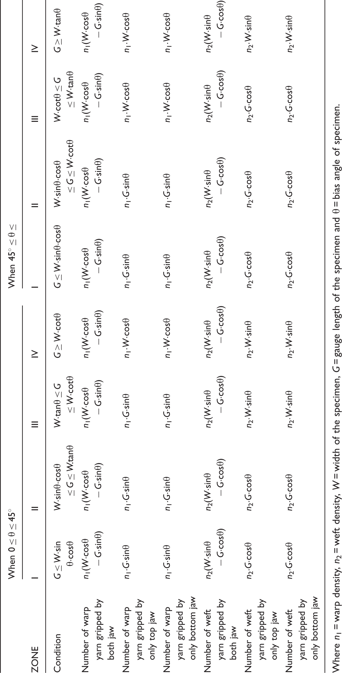
Where n1 = warp density, n2 = weft density, W = width of the specimen, G = gauge length of the specimen and θ = bias angle of specimen.
From above mathematical analysis, it is concluded that gripping zone varies with the changes in the values of W and G at different bias angle. Changes in zones also change the number of yarns gripped between the jaws. In case of Zone I, the numbers of yarns gripped by both the jaw is highest, but it reduces while going towards Zone IV. Therefore, it is required to select optimum sample dimension, so that it come under lower zone and have maximum number of yarns gripped by both the jaws and minimum number of yarns gripped by neither of the jaws. Figure 18 predict the zones at different bias angle for different values of W and G. It can be seen from this figure that by keeping constant width of specimen if the gauge length increases then most of the yarns of the specimen tends towards Zone IV which is undesirable. Similarly, if width increases for constant gauge length, most of the yarns of the specimen tend towards lower zone I which is desirable.
Zone prediction with varying specimen width, gauge length and bias angle.
Therefore, specimen with lower gauge length and higher width will be better. But selection of too low gauge length is also not desirable because here is the chance of neglecting randomly distributed weak point inside specimen. Again too high width is also not desirable as it cost the sample and the normal jaw width available from Tensile Testing Instrument is also limited which is mostly in the range of 8 to 10 cm. If we consider the ASTM D 1683 standard test method for the measurement of failure in sewn seams of woven apparel fabrics, here the selected front jaw width is 2.5 cm, back jaw width is 5 cm and gauge length is 7.5 cm. It can be seen from Figure 18 that the sample with dimension 2.5 cm × 7.5 cm (W × G) and 5 cm × 7.5 cm (W × G) of width (W) and gauge length (G) comes under Zone IV for some bias angle. Therefore, by considering all these factors, the selected optimum dimension is 8 cm width and 7.5 cm gauge length in which it comes under lower zones of II to III for all bias angles.
Conclusions
Determining test specimen size is an important issue while characterising the tensile behaviour at various bias angles of parachute canopy fabric. The present study is started with the slit method of seam strength measurement using specimen dimension used by earlier researchers. The following conclusion has been drawn from present work:
Angle of bias (an acute angle between warp and specimen length/test direction) and size of test specimen directly affect the tensile characteristics of unseamed and lapped seam parachute fabric. In the case of both seamed and unseamed fabric, if the bias angle increases from 0° to 45°, breaking strength and elongation first decrease and then increase up to 45°. If bias angle continue to increase from 45° to 90°, the trend of tensile characteristics is almost symmetric to 45° due to the use of plain square fabric. It is found that the tensile characteristics measured through these methods are not appropriate as many times breakage starts earlier than usual through slit line in case of seamed specimen and towards jaw in the case of unseamed specimen. All these results are fairy less than true expected results as parachute canopy is made endless devoid of uncontrolled edge yarns. The dominating factors that influence the aforesaid behaviour are the numbers of different category of warp and weft yarns available between the grip lines. For a particular width of specimen if the gauge length higher than a specific limit, most of the yarns of the specimen tend towards Zone IV (where the number of yarns gripped by both the grip lines becomes zero). This leads to wrong prediction of tensile performance of the material. Therefore, it is recommended to select the sample dimension such that it should lie within Zone I to III (where the number of yarns gripped by neither of the grip lines becomes zero). But as the selection of zone I requires sample with lower gauge length, this may neglect the randomly distributed weak point inside the specimen and can results higher strength. In the present study, the developed mathematical model for predicting the sampling zones and the numbers of different category of warp and weft yarns available between the grips can be applied for both square and non-square fabric. Furthermore, an optimum sample dimension of W = 8 cm and G = 7.5 cm is finally postulated for proper comparative study of unseamed and seamed square plain fabric because in this case neither gauge length nor width is too high and most of the yarns also come under lower zones (where the number of yarns which are gripped by both the grip lines approaches towards maximum). Although the postulated specimen dimension is used for testing the tensile characteristics of parallel stitched specimen, it will work for oppositely stitched specimen also as the selected parachute fabric has square plain structure.
The novelty of present research includes the postulation of specimen dimension through which one can compare the tensile characteristics of unseamed and seamed square plain parachute canopy fabric at different bias angle which in turn is useful for design and development of parachute. A model has also been generalised and is given in Table 7 which can be used for the prediction of sampling zone for any type of woven fabric. On the basis of selection of sample dimension, this model helps in calculating the number of different category of warp and weft yarns available between the top and bottom grips in different zone.
Footnotes
Declaration of Conflicting Interests
The author(s) declared no potential conflicts of interest with respect to the research, authorship, and/or publication of this article.
Funding
The author(s) received no financial support for the research, authorship, and/or publication of this article.