
Abstract
In the present study, a strategic designing of multilayer shield was planned to enhance the multiple reflection phenomenon to achieve maximum absorption properties in microwave frequency (C & X band) range. Multi-layer EMR shields were developed using pure cotton fabric and conductive woven fabrics, incorporated with copper- based & silver-plated hybrid yarn. First of all, single layer fabrics were produced in five variants, nomenclature as L1A (pure cotton) L1B, L1C (copper-based hybrid yarn), LS1B and LS1C (silver plated hybrid yarn). These five variants were used to prepare four sets of double & triple layer fabric. In both double and triple layer composition, L1A fabric (pure cotton) was used as top layer followed by B and C series fabrics, containing copper and silver-plated hybrid yarn. The EMSE performance in C and X band frequency range of single layer, double layer and triple layers in terms of scattering parameters S11(reflectance) & S21 (transmittance) in vertical and horizontal wave polarization was studied. It was found that number of layers, layer composition, orientation of metallic yarn, frequency and EM wave polarization have significant influence on overall electromagnetic shielding effectiveness.
Keywords
Introduction
Researchers and innovators are pushing forward technological development utilizing high frequency electromagnetic waves in 5.8 to12.4 GHz (C & X band) frequency range for point-to-point communication, high frequency internet services, WIFI, distant communication, radar navigation, commercial, military and medical applications etc. High frequency devices may not only entail ease and comfort of our life, ensure promising business opportunities but may have adverse environmental impacts. Hence, the benefits and the potential risks need to be accessed judiciously. The problem of protection against high energy microwaves EM radiation is typical due to high intensity reciprocal interference of electronic instruments working in close proximity [1–6]. Furthermore, uncontrolled long-term exposure to these radiations imposes hazardous consequences on living organism creating potential health risk even jeopardizing their life [7]. Electromagnetic shielding is probably best option to mitigate the hazardous effect of unwanted microwave radiation. Electromagnetic shielding effectiveness (EMSE) is accessed by three phenomena i.e. reflection, absorption, and transmission. One more phenomenon is associated with it is called multiple reflection. At high frequency interaction, specifically in multilayer shield, this phenomenon creates an additive effect to the absorption [8]. Generally, in microwave frequency range, the reflection dominant shielding is not preferred. If the shield solely works on reflection mechanism, then the high frequency reflected wave can be hazardous to workers. Hence it is required to mitigate high frequency EM radiations by suitable shielding materials that preferably absorb EM waves [9,10].
Recently, textile-based shields, specifically woven fabrics are getting focus of attention due to its light weight, flexibility, convenient for application, and relatively lower cost of production. Though, it requires some prior consideration in various aspects of design and fabric parameters. Fabrics are anisotropic in nature, having interspaces between warp and weft threads and possess discontinuities in conductivity due to interlacement order and the presence of nonconductive fibers [11]. When an EM wave is incident on it, the geometric orientation of the electric field vector decides the polarization property of transverse waves. In linear polarization, the fields oscillate in a single direction vertically or horizontally. In present scenario, there is a need to strategically design broad-band EM shield, which is able to neutralize electromagnetic radiation under both polarized conditions [12].
A number of studies related to the effect of number of layers on EMSE conducted by researchers confirm that the EMSE increases with an increase in the number of conductive fabric layers [1–9]. Prerumalraj et al. 2009 [13] produced copper core yarns to make twill and plain-woven fabrics, it was observed that, the EMSE of double layered fabrics in both weave configurations increases in comparison with their single layer variants. Das et al. 2009 [14] in their study also verified that the EMS effectiveness increases with the increase in the number of fabric layers. They observed that the shielding for any material is directly proportional to the thickness of the material apart from the other parameters that are related. The EMS effectiveness increases with the increase in number of layers, may be due to the fact that one layer above the other can cover the apertures effectively and restricts the direct path of EM wave.
The concept of enhanced absorption in a multilayer system was explored by Brzezinski et al. (2009). [8] They presented the assumptions for designing of multilayer textile polymeric shielding materials in 1– 8 GHz frequency range. They concluded that multiple internal reflections, between successive layers, played a dominant role to enhance absorption phenomenon and overall shielding effectiveness. To validate this assumption Brzezinski et al. (2009), (2012) [9,10] designed a new generation of effective shields against electromagnetic radiation with high absorption coefficients and excellent EMSE. The authors exploited the multiple internal reflections phenomenon with the help of 3 to 6 thin component layers of textile-polymeric shields having different values of relative electrical permittivity and magnetic permeability.
Apart from multiple reflection, the effect of orientation and placement of conductive material in a shield has also been studied by various researchers. Lou et al. (2016) [15] developed plain woven fabrics using 500 denier polyester filaments as warp and optimal SS/PET and Cu/PET wrapped yarns in different proportions as weft yarn. A six-layer multilayer configuration was formed by laminating all at 0°, a combination of 45°/90° and 0°/90° laminating angles. It was also reported that a combination of (45°/90°) laminating angle contributes highly to the EMSE in comparison with first and third configuration having same (0°& 90°) orientation, respectively. In another study Lou et al. (2017) [16] verified that the multi layered conductive fabrics plied with the same orientation exhibited lower EMSE due to consistent conductive networks and fewer circuits per unit area. It was found that a change in layer orientation results in a denser conductive network, more circuits per unit area and promote multiple reflection of EM waves in the shield.
The effect of EM wave polarization on EMSE was undertaken by some researchers in lower frequency range. Ortlek et al (2012) [12] studied the electromagnetic shielding characteristics of woven fabrics made of steel-based hybrid yarn in the frequency range of 30 MHz-9.93 GHz under different polarization of EM wave. It was concluded by them that the wave polarization, weave, thread density and placement of conductive hybrid yarn in warp and weft direction were significant parameters affecting electromagnetic shielding characteristics of woven fabric.
Some researchers have adopted nonconducting layer as an important component in multilayer shield. Erdumlu and Saricam (2016) [17] designed a specific layer configuration, containing pure cotton layer along with fabrics containing cotton/metal-wrapped hybrid yarns, suitable for garments with special protective capabilities. It was found that the use of conductive fabrics under pure cotton fabric did not interrupt the shielding effectiveness of the conductive fabrics.
On the basis of above findings, it can be inferred that the absorption based shielding mechanism is one of the primary requirements for designing shields at high frequency range. A multilayer shielding mechanism can effectively enhance absorption through multiple reflection inside the shield. It was found that studies based on multilayer shielding materials emphasized on design considerations, layer composition, laminating angle, array spacing of conductive fibers, conductive coating etc. However, none of the above studies have comprehensively evaluated the reflectance and transmittance component against vertical and horizontal polarized EM waves in C and X band frequency range.
In the present study, a strategic designing of multilayer shield was planned to enhance the multiple reflection phenomenon and maximum absorption properties in microwave frequency (C Band & X band) range. The multiple reflections generally require effective penetration of microwave in conductive volume of the shield. To achieve large conductive volume different multi-layer EM shields were developed in double and triple layers, using pure cotton fabric (L1A) as top layer and conductive woven fabrics, incorporated with copper- based hybrid yarn & silver-plated hybrid in successive layers. The purpose of this selection was intended for effective penetration of microwave in multilayer shield to ensure maximum absorption. The composition of double layer includes the layer configuration of L1A fabric followed by B and C series fabrics, containing copper and silver-plated hybrid yarn. Four configuration sets of double layers were developed and nomenclature as: L2AB, L2AC (containing copper hybrid yarn), and LS2AB, LS2AC (containing silver plated hybrid yarn). In triple layer composition, ACB & ABC fabric were opted as layer composition. Thus, four configuration sets nomenclature as: L3ACB, L3ABC (copper variants) and LS3ACB, LS3ABC (silver plated variant). The fabric A represents L1A fabric (top layer) fabric B composed of copper based/silver plated hybrid and fabric represented by L1B and LS1B (middle/bottom layer). The composition of fabric C consists of copper based/silver plated hybrid yarn in both warp and weft is represented by L1C & LS1C (middle/bottom layer), respectively. The main aim of selection of this layer composition in the middle and bottom layer was to create different alignment of conductive yarn in a multilayer system. The EMSE performance in C and X band frequency range of single layer, double layer and triple layers in terms of reflectance, transmittance in vertical and horizontal wave polarization is presented.
Material and method
Development of metallic hybrid yarn
In present study, two types of metallic yarn i.e. copper and silver-plated copper were used to develop multilayer electromagnetic shield. First of all, 70-micron copper wire was taken as a base material. The copper wire was drawn and flattened up to 0.2 mm. This flattened copper was taken as sheath material over three ply 16 tex cotton yarn to prepare composite yarn. The flattening of copper wire was done to ensure proper gripping over core yarn. The silver-plated wire was also developed by electroplating silver over the flattened copper wire. To achieve this the copper wire and silver metal bar were made cathode and anode, respectively. Silver cyanide (Ag CN) was used as an electrolyte. The silver anode bar gives up electrons so the anode bar gradually dissolves to replenish the silver ions in the solution and the anode gets smaller as the copper wire becomes silver plated. Finally, 10 g/kg silver was electroplated on the copper wire.
Both set of metallic yarns were wrapped over three-ply of 16 Tex cotton yarn on a specially designed twisting machine separately. The turns per inch of wrapping were 40 and count of final yarn was 182 Tex {48 Tex (three-ply 16 Tex), 134 Tex (metallic wire)}. From this composite yarn a 300-Tex hybrid yarn was produced by twisting two plies of 59-Tex cotton and single ply of 182 Tex composite yarn. The turns per inch of this three-plied yarn was five. The procurement of raw materials and the manufacturing process of composite and hybrid yarn was performed at M/S Vishwanath prasad, Varanasi (India). A brief flow chart of the process and photograph of copper and silverplated hybrid yarn is shown in Figures 1 and 2 respectively. The detail specification of both types of hybrid yarn are presented in Table 1.

Flow chart of composite/hybrid yarn (a: - Copper and b: - Silverplated).
Developed Conductive Yarn (a: - Copper based Composite Yarn, b: - Silver Plated Composite Yarn, c: - Copper based Hybrid Yarn, d: - Silverplated Hybrid Yarn).
Conductive yarn specification.

Development of multilayer fabric
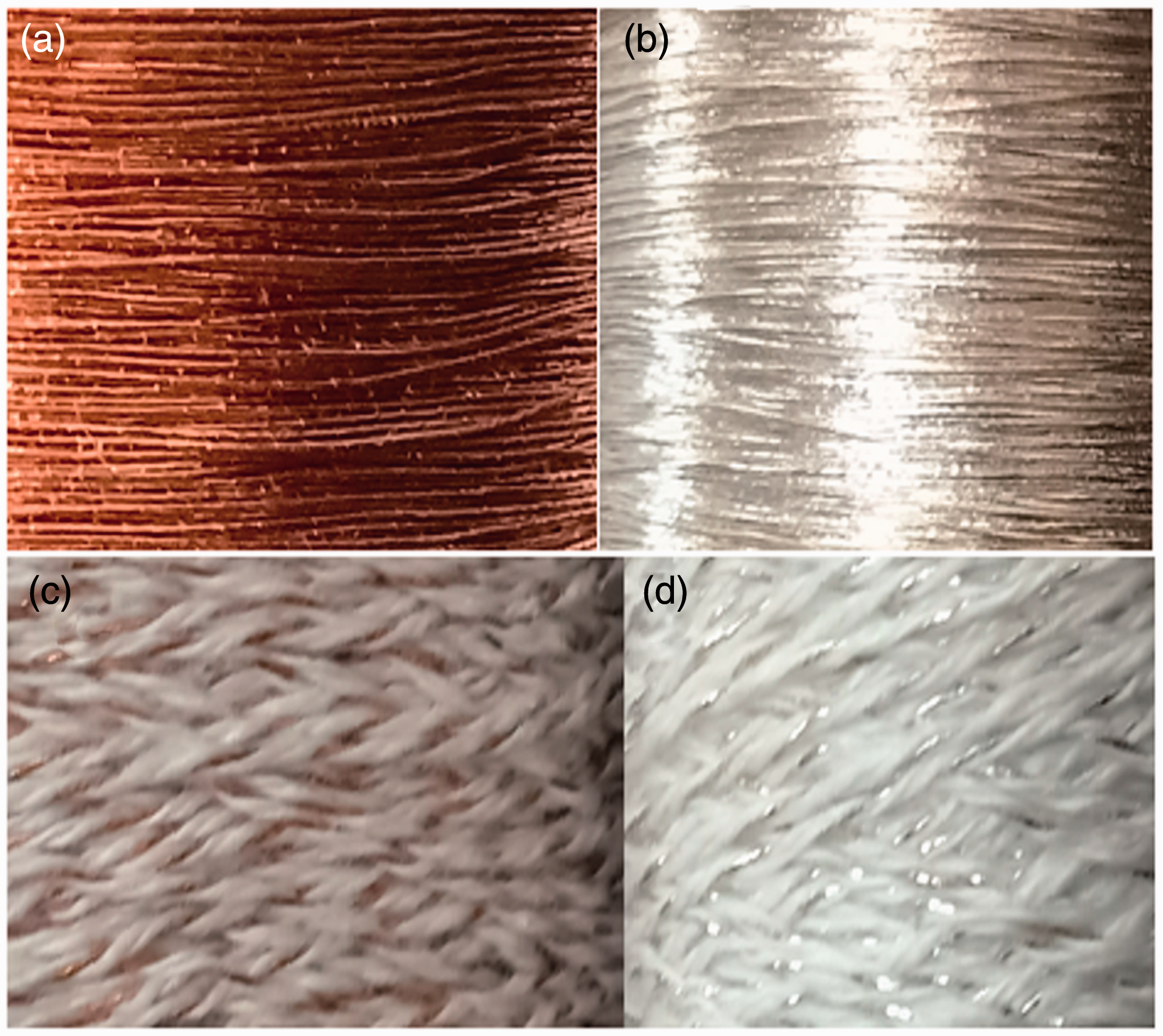
Initially, single layer fabrics were produced with 3/1 twill weave in three different series on a four-shaft dobby loom. The reed count of 20 s stock port (6 threads per dent) was opted for sample preparation. The three-fabric series were identified as following: “A” series comprises of 100% cotton, the second series, “B” having cotton warp and hybrid yarn in weft, the third “C” series, composed of 1/3rd hybrid yarn, 2/3rd cotton yarn in the warp and hybrid yarn in weft. From these fabric series, five variants, nomenclatured as L1A (pure cotton) L1B, L1C (copper-based hybrid yarn), LS1B and LS1C (silver plated hybrid yarn) were developed. The photographs of face and backside of developed single layer fabric samples are presented in Figure 3. These five variants were used to prepare four sets of double & triple layer fabric in different layer configurations. The top layer in both double and triple layer composition consists of L1A (pure cotton) fabric followed by conductive fabric, incorporated with copper- based & silver-plated hybrid yarn. The detailed specification, layer composition and nomenclature of fabric are mentioned in Table 2.

Single layer fabric samples for multilayer composition.
Specifications of single and multilayer fabric.

Material characterization
Fabric Parameters
The fabric parameters were measured as per following standards.

Characterization of electromagnetic shielding effectiveness
The characterization of electromagnetic shielding effectiveness properties of a material indicates how incident EM waves are attenuated by a shield quantitatively, expressed in decibels (dB). Many researchers have proposed theoretical models based on measured or predicted shielding effectiveness of various materials and explained various standards such as MIL-STD-285 (1956), IEEE-STD 299 and ASTM D4935 etc., but direct comparison of the relative performance under different methods lacks the harmonization of standards. This is due to the standard measurement methods depend on the properties of shields/parameters of measurement setup, such as; the sample size, shield topology, configuration of the test setup, the distance between the source and test sample etc. The most popular standard, MIL-STD-285 (1956), termed as the Military Standard was originally developed in the USA for testing large enclosures and shelters to a frequency limit of 400 MHz, is obsolete and lacks consistency. The modified versions of the MIL-STD-285, nomenclature as IEEE-STD-299 (1997) has a wide range of working frequencies up to 100 GHz, but this standard cannot be used for measuring the SE of small-sized to medium-sized enclosures. In aforementioned standard high-impedance electric fields were used that cause EM leakages. To overcome this another method, ASTM E1851was adopted. However, this system may not be applicable for evaluating individual components and mainly used for comparing different commercial enclosures and shelters. To assess the shielding effectiveness of sheet materials the “Insertion loss method”, utilizes a coaxial transmission line (ASTM D4935 standard). This measurement technique is practically free from resonance-like effects and produces smoothest experimental curves. However, there are certain limitations, for example; the measurement method is valid over a frequency range from 30 MHz to 1.5 GHz and not capable to investigate shielding parameters versus EM wave polarization.
Despite the plethora of standards mentioned above, there is no standardized method available to assess the SE of textile materials and still a daunting task for researchers. However, some researchers recommended “Free-space method” to characterize complex electromagnetic properties of polymeric and textile materials. Patel et al 2013 [18] found it as reliable measurement method for textile materials. Dvurechenskaya & Zielinski 2011 [19] in their study opted free-space transmission technique for investigation of woven and non-woven (anisotropic materials). They found that this measurement technique enables to measure EMSE, depending on wave polarization, which is especially important for anisotropic materials. Furthermore, this technique is non-destructive, does not require a special sample preparation, uses large flat sheet for testing and is suitable for materials investigation in wide frequency range. Another advantage of this method is its applicability for higher frequency range measurements. In present study the free space technique based on ASTM-D3380-14 standard was used for assessment of EMSE of multilayer shield in terms of scattering parameters.
Measurement of scattering parameters
The measurement of scattering parameters S11 (reflectance) & S21 (transmittance) of multilayer fabrics were performed through free-space technique. This technique is commonly used for electromagnetic characterization of the textile based shielding material due to nondestructive and contactless measurement technique furthermore, it requires minimum effort for the sample preparation. [20,21] The free-space measurement system consists of a pair of spot-focusing horn lens antennas, mode transitions, coaxial cables, and a network analyzer system. Spot focusing antennas are compact and provide plane wave illumination for the materials at the testing point. A pair of focusing horn lens transmitting and receiving antenna were mounted on movable bases on the top of an aluminum table with dimensions 1.83 m × 1.83 m. Although the distance between the antennas was 61 cm.The sample, 15 cm × 15 cm in dimension was fixed tightly by a Plexiglas sample holder whose base and frame were arranged outside of the area of wave propagation. Thru-reflect & line setup was used for calibration of the system, the sample was placed at the focal plane of antennas. The measurement was carried out using the standard transmission line method as per ASTM-D3380-14 standard.
In present study, the network analyzer system was operated in C band (5.8-8.2 GHz) & X band (8.2-12.4 GHz) frequency range separately. The power generated by the network analyzer transferred via coaxial cables and power waves is emitted and received by horn antennas. Network analyzer measured the S-parameters i.e., both magnitude and phase of reflection and transmission coefficients from the port 1 to port 2 as a function of frequency. The experimental set-up of the free space measurement system is shown in Figure 4. The readings were extracted in terms of the measured reflectance (S11) and transmittance (S21) parameters measured over 1001 sample points between 5.8 to 8.2 in C band and between 8.2- 12.4 GHz in X band frequency range with each measurement being carried out eight times in order to average out each frequency point. The shielding effectiveness in terms of reflection and transmittance is obtained in negative values and the unit is expressed in decibel (dB), as a higher negative value nearer to zero, indicates higher reflectance and lower negative values approaching away from zero is treated as higher shielding effectiveness in terms of transmittance. However, some researchers take positive absolute value for graphical presentation. In such case, the higher positive values indicate higher shielding in terms of transmittance and for reflectance, lower positive value will indicate higher reflectance. The electromagnetic shielding in terms of reflection and transmission loss are expressed in logarithmic descriptions of the ratio of the power reflected (PR) or power transmitted (PT) to power supplied by the system (P0), respectively.

Experimental set-up of the free space measurement system.
R (dB)= 10 log (PR/P0)
T (dB)= 10 log (PT/P0)
Result and discussion
The electromagnetic shielding effectiveness (EMSE) performance of single layer, double layer and triple layer fabrics, containing copper-based hybrid and silver-plated hybrid is presented in C and X band frequency range. The EMSE property resembles the total shielding capacity which radically depends on the magnitude of reflected, absorbed and residual transmitted electromagnetic (EM) waves through a shield. The EMSE is expressed as negative value in dB, represents reflection and transmission loss. Generally, to have better clarity of expression, the relative positive values are opted for the graphical representation of EMSE in terms of reflectance (S11) and transmittance (S21). In this study the positive values of reflectance and transmittance are used for analysis. The lower reflectance value presented in dB, means better reflectance. The zero dB reflectance value indicates the total incident waves are reflected from the surface of the shield. Hence, the positive values approaching away from zero values indicate poor reflectance property of the shield. In contrast zero dB transmittance (S21) indicates the whole incident EM wave is transmitted through the shield without any attenuation. So, the higher value (positive) signifies, better EMSE.
The effect of EM wave polarization (vertical and horizontal) & layer configurations on EMSE of single layer & multilayer fabrics is also undertaken in this study.
Analysis of single layer fabric
Single layer fabrics were produced in five variants, nomenclature as L1A (pure cotton fabric) L1B, L1C (fabric with copper-based hybrid yarn), LS1B and LS1C (fabrics with silver plated hybrid yarn). All the five variants were used for composition of double and triple layers with different layer configurations. Hence, the EMSE performance of single layer was undertaken for in depth analysis of multilayer fabric sets.
Analysis of EMSE properties of single layer in C & X band frequency range in vertical wave polarization
The reflectance (S11) and transmittance (S21) performance in C & X band frequency range, of a single layer is presented in Figures 5 and 6 The EMSE performances of both S11 and S21 parameters are mutually correlated with each other. The L1A composed of pure cotton shows poor reflectance and transmittance validating the previous studies that conductivity is essential for achieving EMS capability.

Reflectance and transmittance trends of single layer in vertical polarization in C band frequency range.

Reflectance and transmittance trends of single layer in Vertical polarization in X band frequency range.
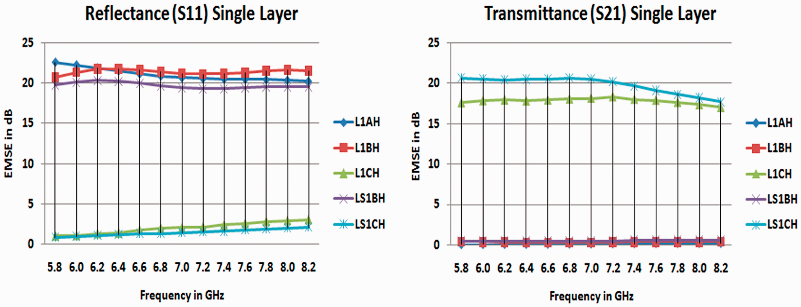
The other fabrics of this series have shown a significant reflectance and transmittance properties. As shown in Figure 5, LS1B fabrics have shown better reflectance property in comparison with the L1B fabric which is obviously due to better conductivity of silver-plated yarn. As a general trend, in all fabric variants, a reflectance peak was observed at 5.8 GHz and it decreases with increasing frequency range. This can be ascribed that reflection phenomenon is related to surface conductivity, as the frequency increases the wave length becomes short and can easily pass through the shield so, the measured reflectivity value decreases. Among the four conductive variants, the LS1B fabric with 0.87 dB reflectance value performed best followed by LSIC, L1C and the least reflectance was observed in L1B fabrics in C band frequency range.
The transmittance curve in C band frequency range clearly indicate that the transmittance value increases in middle frequency region between 6.4 to 7.2 GHz range, then declined in upper frequency region between 7.6 to 8.2 GHz. However, the decline in transmittance property in this region was not same as it was observed in reflectance curve. This can be ascribed that the transmittance property depends on reflectance and absorption phenomenon. It is clear from the obtained trend that in the middle and upper frequency range the absorption of EM waves is also taking place. It can be seen that the L1SB fabric has shown the best EMSE of 21.61 dB followed by LS1C, L1B and least transmittance value17.8 dB was observed in case of L1C fabric.
The reflectance and transmittance of single layer variants in X band frequency range is presented in Figure 6. It can be seen that, the LS1C fabric with 1.13 dB exhibited the best reflectance property in comparison with the all-other variants, followed by LS1B, L1C and least 4.62 dB was observed in L1B fabric. The LS1C fabric is made of silver-plated hybrid in both warp and weft direction. The silver-plated yarn is more conductive than copper hybrid yarn. In all conductive fabric variants (B& C series) it was observed that reflectance value decreases continuously from 8.2 GHz to 11 GHz frequency. From 11.4 to 12.4 GHz a massive decline in reflectance was observed, which can be seen from the rising curve peak of reflectance curve in Figure 6 this is due to shorter wave length of wave at upper part of the frequency range. The rising peak of reflectance and a stagnant and a very low decline in transmittance curve clearly indicates that a lot of energy of EM waves is absorbed inside the shield. The stagnant to moderate tilt in graph curve of transmittance and high peak of reflectance curve between 11.8 to 12.4 GHz frequency shows that maximum absorption is taking place in this range. The best EMSE of 16.95 dB was observed in LS1C fabric, followed by LS1B, L1C and least transmittance value of 12.84 dB was observed in L1B fabric at 8.2 GHz frequency.
From the obtained trend in both frequency bands, it was found that the silver-plated variants have shown better EMSE properties that copper variants. This was obviously due to better conductivity of silver-plated yarn. Furthermore, it was observed that both L1C & LS1C have shown less transmittance value in comparison with their respective B series fabrics. Though, the metallic content in C series fabric was more than B series fabrics. This can be surmised when high intensity EM wave interacts with conductive fabric additional fields are created. The C series fabric is composed of 1/3rd metallic hybrid yarns in warp and hybrid metallic yarns in weft. The presence of metallic yarn in warp created more apertures which enhances the transmittance of EM waves. Whereas, in case of B series fabric, the warp is composed of cotton so, comparatively fewer apertures were observed. In spite of lesser metallic content, the additional field induced by the high intensity wave, enhance the attenuation of EM wave, so better transmittance values were observed in B series fabric indicating that the apart from metal content the placement fabric apertures played an important role to achieve EMSE, similar findings were also observed by Rajendrakumara & Thilagavathi (2012) [11]. Furthermore, it was observed that unlike C band, where in the middle range of frequency an improvement in transmittance property was observed in all conductive variants, but similar trend was not found in X band frequency range. The transmittance value decreases with increasing frequency range. Nevertheless, comparatively slow decline of transmittance against sharp decline of reflectance clearly indicates the contribution of absorption phenomenon for achieving EMSE. However, the EMSE in X band was lower than the C band. It can be concluded that X band has higher energy and smaller wave length (3.75 to 2.5 cm) in comparison with the C band (7.5- 3.75 cm). The wavelength is inversely proportional to the frequency and photon energy is directly proportional to the wave frequency. The smaller wave length can easily penetrate the fabric pores with lesser interaction with the fabric surface. Hence, all the samples have lower EMSE in terms of reflectance and transmittance in X band range.
Analysis of EMSE properties of single layer in C& X band frequency range in horizontal wave polarization
The EMSE performance in terms of reflectance and transmittance in C & X band frequency is explored in Figures 7 and 8. The fabric L1AH also showed poor reflectance and transmittance in horizontal polarization. However, unlike, vertical polarization the B series fabrics L1BH & LS1BH showed poor reflectance and transmittance performance in horizontal polarization, in both frequency range indicating, that this type of fabric is not suitable for shielding against the horizontal polarized EM waves. This is due to absence of metallic hybrid yarn in warp direction. The horizontal polarized waves propagate parallel to the weft direction of fabric. The parallel waves easily passed through the gap between the metallic wefts. Only some waves directly interacting with the metallic weft yarn is attenuated. This phenomenon was seen in both L1BH & LS1BH fabric. However, in the case of vertical polarized waves the EM waves are perpendicular to the weft direction. The presence of metallic weft yarn in B series fabric was able to counteract the EM waves, hence better shielding performance was seen with vertically polarized EM waves. The results obtained in horizontal polarization of this fabric were found in line with the previous observations of Ortlek et al. (2012) [12]
Reflectance and transmittance trends of single layer in horizontal polarization in C band frequency range.

Reflectance and transmittance trends of single layer in Horizontal polarization in X band frequency range.
A significant EMSE performance in terms of S11 & S21 parameters was observed in both L1CH and LS1CH series fabric. It can be surmised that when the parallel waves of horizontally polarized strikes the fabric surface the gap between the adjacent weft is well compensated by the presence of 1/3rd metallic hybrid warp. The maximum EM waves are arrested which was not possible with the B series fabrics.
The reflectance and transmittance performance in C band frequency range is presented in Figure 7. The reflectance value of both L1CH & LS1CH decreases with increasing frequency. The LS1CH fabric showed better reflectance (S11) than L1CH. The best reflectance value of 0.85 dB & 1.04 dB was observed at 5.8 GHz frequency in LS1CH & L1CH fabrics respectively. The decline in reflectance was also observed with increasing frequency. However, the transmittance value did not follow the same trend. An increase in transmittance value was observed from 6.0 to 7.2 GHz frequency, the highest transmittance value of 20.70 dB (at 6.8 GHz) & 18.35 dB (at 7.2 GHz) was obtained in LS1CH & L1CH fabric, respectively.
In X band frequency range, shown in Figure 8, it can be seen that the reflectance value of both L1CH & LS1CH decreases with increasing frequency. The fabrics LS1CH & L1CH has shown almost same maximum values of 1.14 dB at 8.2 GHz frequency. However, throughout the frequency range LS1CH fabric with 2.99 dB has shown better average reflectance than of L1CH fabrics having an average value of 3.63 dB. Identical to vertical polarization results, similar trend of reflectance and transmittance behavior was observed in 11.8 - 12.4 GHz frequency range. The LS1CH & L1CH fabric have shown highest transmittance value of 16.22 & 14.10 dB at 8.2 GHz frequency range. The transmittance gradually dropped and reached a minimum value at 12.4 GHz frequency.
From the abovementioned analysis, it can be observed that the C series fabrics have shown excellent shielding performance against both vertical & horizontal polarized EM waves. It can be inferred that; warp and weft in a fabric are two systems independent components. If the conducting hybrid yarns are incorporated in one direction, then the EM waves shielding is achieved in that direction only, as was observed in B series fabrics. For achieving EMSE against both types of polarized EM waves, it is necessary to incorporate conductive yarn in both warp and weft direction. This interpretation was also explored by Ortlek et al. (2012). [12]
Analysis of double layer fabric
Double layer fabrics were developed in four configurations sets from the aforementioned five variants of single layered fabrics. The nomenclature of four configuration sets is: L2AB, L2AC, LS2AB and LS2AC.
Analysis of EMSE properties of double layer in C & X band frequency range in vertical wave polarization
In the previous section we can see that the L1A fabric, composed of pure cotton showed poor reflectance and transmittance was deliberately chosen as first layer with the intention to allow the microwave to enter inside the fabric. The specific composition of double layer with top layer as non-conducting cotton makes an easy passage for microwaves inside the shield. The high energy microwaves interacting with second conductive layer induce current and the molecules of conducting layer oscillate on their axis. Due to this phenomenon some part of EM waves is reflected back through the pores of non-conducting layer and contribute positively to the reflection mechanism. Wei et al. (2018) [22] It is interesting to note that the total shielding effectiveness in terms of transmittance improved due to presence of non-conducting first layer. This trend is also validated by the previous study presented by Zhu et al (2007) [23]. The EMSE performance in terms of reflectance (S11) and transmittance (S21) in C and X band frequency of double layer is presented in Figures 9 and 10 respectively. It can be clearly seen that the reflectance value of all four variants decreased considerably in comparison with their respective single layer components. The decrease in this value can be ascribed due to presence of L1A (pure cotton) layer. However, the transmittance value and the overall EMSE of double layer variants increased in comparison with single layer variants. It can be inferred that considerable amount of EM wave energy is also absorbed. This additive effect of absorption phenomenon, contributed to the total shielding effectiveness throughout the frequency range, consequently the overall EMSE increased. Similar trend was also observed by Zhu et al. (2007) [23] in nonwoven fabrics.

Reflectance and transmittance trends of double layer fabrics in vertical polarization in C band frequency range.

Reflectance and transmittance trends of double layer fabrics in vertical polarization in X band frequency range.
It can be seen from Figures 9 and 10, in both frequency range, the reflectance decreases with the increasing frequency range and all variants exhibited their best reflectance values at initial frequency of 5.6 & 8.2 GHz in C and X band, respectively.
As shown in Figure 9 in C band frequency range, LS2AC has shown its best reflectance value of 2.42 dB followed by L2AC, LS2AB and the least 2.82 dB was observed in case of L2AB fabric. A consistent decline in reflectance property was noticed throughout the frequency range. The silver variants have shown remarkable transmittance performance. The LS2AC fabric attained a maximum value of 23.58 dB at 7.2 GHz frequency which was found to be the highest value among all four variants. In LS2AB same trend was observed until 7.0 GHz frequency where highest EMSE of 22.73 dB was observed. Among the copper variant L2AC fabric with 21.96 dB performed better than L2AB fabric.
In X band frequency range, fabric LS2AC has shown best reflectance performance of 2.32 dB among all four variants followed by LS2AB, L1AC and the least reflectance value of 2.95 dB was observed in L2AB fabric. The reflectance curve shown in Figure 10 indicated that the reflectance value declined steadily with increasing frequency range. A sharp peak of curve was observed between 11.4 to 12.4 GHz frequency resulted in a massive decline of reflectance property, in all double layer variants. This is mainly due to shorter wave length of higher frequency range.
The EMSE in terms of transmittance is also presented in Figure 10. The EMSE performance of double layer can be effectively understood by a comprehensive analysis of reflectance and transmittance curve. As discussed, the reflectance value decreases with increasing frequency, with similar trend also being observed in the transmittance property. However, on the analysis of transmittance curve, it can be seen that, any significant change was not found, a slow and steady decline was observed, specifically in between 11 to 12.4 GHz, where the curve almost became flat with nominal decline. This indicates that maximum energy of EM waves was absorbed between 11 to 12.4 GHz frequencies. The transmittance curve clearly indicates that absorption phenomenon also played a dominant role in achieving total shielding effectiveness. The best transmittance value of 17.54 dB and the least transmittance of 14.99 dB was found in LS2AC and L12AB fabrics at 8.2 GHz frequency, respectively. In all four variants a slow and steady decline in transmittance peak was observed throughout the whole frequency range. In contrast, a sharp peak of reflectance in between 11 to 12.4 GHz frequency range indicates that at this specific frequency range the absorption of energy of EM waves was prominent. From the obtained average value, it can be concluded that silver plated variants are more effective than their copper-based variants. Furthermore, the C series fabric with more metallic content was found better than B series fabrics. The presence of non-conducting layer has positively contributed to enhance absorption and overall shielding effectiveness performance against the vertically polarized EM waves.
From the obtained test result, it can be said that the induction of nonconductive cotton fabric as top layer, in double layer fabric composition has enhanced the EMSE and absorption behavior throughout the C & X band frequency range.
Analysis of EMSE properties of double layer in C band frequency range in horizontal wave polarization
The EMSE in horizontal wave polarization in C & X band frequency range exhibited the same trend as was observed in single layer. As shown in Figures 11 and 12, the fabric composition, L2ABH & LS2ABH containing conductive yarn in weft direction, showed poor reflectance and transmittance in horizontal polarization. The reason for their poor reflectance and transmittance were same as was explained in single layer composition. However, the fabric variants L2ACH & LS2ACH containing copper-based hybrid yarn and silver-plated hybrid yarn in warp and weft respectively, showed better reflectance and transmittance properties in comparison with their B series variants. Therefore, detail analysis of reflectance and transmittance performance, of these fabrics are undertaken in this section.

Reflectance and transmittance trends of double layer fabrics in horizontal polarization in C band frequency range.

Reflectance and transmittance trends of double layer fabrics in horizontal polarization in X band frequency range.
The reflectance and transmittance curve pattern in C band frequency is shown in Figure 11. The reflectance value of both types of fabrics, decreases with increasing frequency. Maximum reflection loss of 2.08 dB was found in fabric L2ACH at 5.2 GHz frequency. In case of LS2ACH almost similar results with 2.09 dB was also seen at the same frequency. The maximum transmittance value of 20.66 dB was found in case of LS2ACH fabric which was marginally below than the results in vertical polarized condition. In both L2ACH & LS2ACH fabrics, the transmittance value decreased gradually from 5.2 GHz frequency until 6.2 GHz frequency and started to increase from 6.4 to 7.0 GHz frequency where maximum shielding of 20.63 and 20.66 dB was observed, respectively.
Analysis of EMSE properties of Double layer in X Band frequency range in Horizontal wave polarization
In X band frequency range, the effect of horizontal polarized EM wave on EMSE in X band is shown in Figure 12, L12AC and LS2AC has shown better performance in terms of reflectance and transmittance in horizontal polarization. The best reflectance value of 2.05 dB was observed in case of LS2AC fabric followed by 2.52 dB in case of L2AC fabric at 8.2 GHz frequency.
The reflectance value of both fabrics declined considerably with the increasing frequency, specifically, between 11.4 to 12.4 GHz frequency range, following the similar trend as was observed in vertical polarization. Maximum EMSE in terms of transmittance performance of 16.36 and 15.39 dB was observed at 8.2 GHz frequency in LS2AC & L2AC fabrics respectively. As per observed trends in vertical polarized results where EMSE decreases with increasing frequency, similar trends were also observed in horizontal polarization.
From the obtained results it can be derived that the placement of yarn in both warp and weft direction is important to achieve overall shielding effectiveness under both polarized condition of wave. The possible reason for poor EMSE of fabric variants of B series might be the nature of propagation of horizontal waves. The horizontal waves propagate parallel to the weft in the fabric axis. The wave interacting with conductive weft can easily be countered. If the warp is not conductive, the wave gets an easy passage through the apertures between the two adjacent wefts placed horizontally in the fabric. Whereas, in case of vertical polarization condition the waves interact perpendicular to the weft in fabric axis, thus, ensuring maximum shielding. In case of fabric variants with C series the presence on hybrid yarn in both warp and weft direction was able to counteract with waves of both polarized conditions ensuring better EMSE. The obtained result was found consistent with the previous study by Ortlek et al. (2012). [12]
Analysis of triple layer fabric
In this study composition of two of layer configuration i.e. ACB & ABC fabric were opted for analysis of EMSE in the triple layer. The fabric A represents L1A fabric, fabric B containing copper based/silver plated hybrid in weft, is represented by L1B and LS1B fabric. The composition of fabric C consists of copper based/silver plated hybrid yarn in both warp and weft direction is represented by L1C & LS1C, respectively. In previous study of double layer, the L1A fabric, composed of pure cotton was deliberately chosen as first layer with the intention to allow the microwave to enter inside the fabric. A similar concept was adopted in triple layer fabric composition with cotton fabric in top layer followed by a composition of either B series or C series in subsequent middle layer and third layer. The main aim of selection of different layer composition in middle and bottom layer was to create different alignments of conductive yarn in a multilayer system. It was observed in the analysis of single and double layer that the B series fabric has shown poor EMSE when subjected to horizontally polarized EM waves. Furthermore, the adoption of nonconductive layer as top layer in a double layer composition has shown better EMSE and has enhanced the absorption of microwaves. To achieve better EMSE under both vertical and horizontal conditions a mix composition of single layers was attempted to study the effect of different layer compositions on reflectance and transmittance behavior of a multilayer system. Triple layer fabrics were developed in four configurations sets from the five single layer variants. The nomenclature of four configuration sets is: L3ACB, L3ABC, LS3ACB and LS3ABC.
Analysis of EMSE properties of triple layer in C & X band frequency range in vertical plane wave polarization
The EMSE performance in terms of reflectance (S11) and transmittance (S21) of a triple layer is in C & X band frequency range is presented in Figures 13 and 14, respectively. It was observed that the reflectance value of all four variants decreased considerably in comparison with their single layer components throughout the frequency range. The decrease in reflectance value was obviously due to presence of L1A (pure cotton) layer. However, the reflection values of triple layers showed better results in comparison with the double layer fabrics. As, described in previous section, the top layer composed of pure cotton, directly interact with the microwave and provide a safe passage for the microwave to transmit through it. The reflection of microwaves occurred as a consequence of internal reflections inside the shield. The inner reflected waves come out through the apertures of the nonconductive top layer. Due to additional conductive layer the positive contribution of reflection was more than the double layer configuration, hence observed reflectance value was high.
Reflectance and transmittance trends of triple layer fabrics in vertical polarization in C band frequency range.

Reflectance and transmittance trends of triple layer fabrics in vertical polarization in X band frequency range.
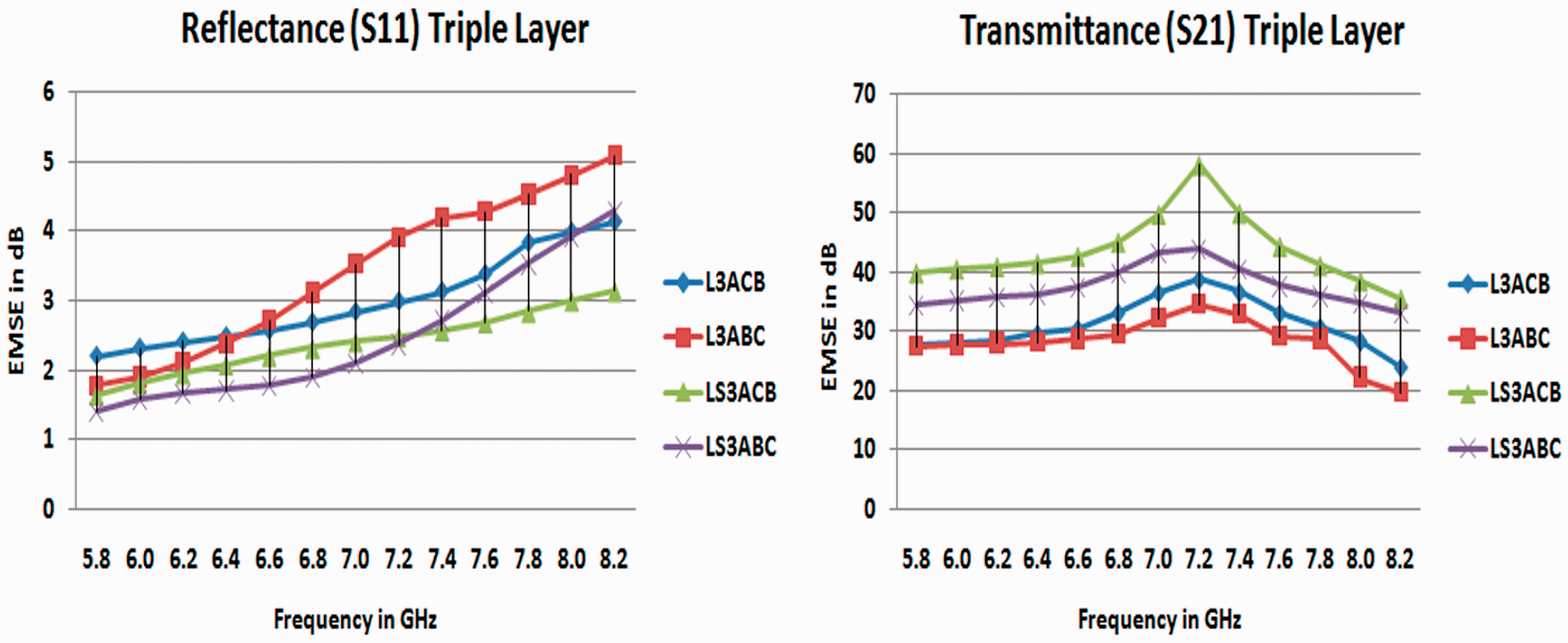
The reflectance and transmittance performance of a triple layer fabric, in C band frequency range is shown in Figure 13. It was observed that the copper based variants, L3ACB & L3ABC have achieved maximum reflectance value of 2.21 dB and 1.78 dB at 5.2 frequency range respectively. The reflectance value decreases with the increasing frequency and these fabrics attained a minimum reflectance of 4.14 and 5.09 dB, respectively. The transmittance of both fabrics improved considerably and consistently from 5.2 to 7.2 GHz, where L3ACB &L3ABC fabrics achieved maximum shielding effectiveness of 38.53 & 34.53 dB respectively. In case of silver plated variants, the maximum reflectance value of 1.64 dB and 1.41 dB was found at 5.2 dB GHz frequency for LS3ACB and LS3ABC fabrics respectively, which is comparatively better than their respective copper variants. However, throughout the frequency range the average reflectance value was 2.4 and 2.47 dB for LS2ACB & LS3ABC fabric.
The transmittance performance indicated that EMSE of both the silver variant fabrics increases with the increase in frequency up to 7.2 GHz, followed the reverse trend of reflectance. Although, the contribution of reflectance followed a sharp decline with increasing frequency range, but the overall EMSE was well compensated by dominant role of absorption phenomenon. The EMSE in both the fabric LS2ACB & LS3ABC reached maximum peak value of 58.07 & 43.89 dB at 7.2 GHz frequency, respectively. After achieving highest peak, the EMSE declined throughout the frequency range. It is noticeable that the rate of decline of reflectance was significantly consistent, while the transmittance graph in Figure 13 did not follow the same rate of decline. Finally, it can be concluded that all variants of triple layer have shown remarkable improvement in EMSE in comparison with their double layer variants.
The EMSE performance in terms of reflectance (S11) and transmittance (S21) of triple layer in X band frequency is presented in Figure 14. The copper based L3ACB & L3ABC fabrics have achieved maximum reflectance value of 2.16 dB and 2.31 dB at 8.2 GHz frequency, respectively. The fabrics LS3ACB & LS3ABC, showed better reflectance with 1.78 & 1.89 dB, respectively. It was noticed from the reflectance curve shown in Figure 14 that the reflectance gradually decreases from 8.2 to 9.8 GHz frequency range and the rate of decline further intensified between 11.4 GHz to 12.4 GHz where a highest peak of curve indicates lowest reflectance. The average reflectance value of 4.02 dB, 4.56 dB, 4.94 dB and 5.39 dB was found in fabrics LS3ACB, LS3ABC, L3ACB and L3ABC fabrics, respectively. Furthermore, the reflectance of fabrics containing silver plated hybrid yarn was better in comparison with their copper-based variants.
As shown in Figure 14, among all four variants, the fabric LS3ACB achieved best reflectance properties throughout the frequency range. It can be ascribed that, the fabric with composition of ACB series fabric has performed better than ABC composition. This is due to the middle layer composition as C series fabric. The C series fabrics contains conductive yarn in both warp and weft direction, with more metal per unit area and better conductivity. Additionally, this fabric series was found more effective as middle layer. The best conductive layer as a second layer in a multilayer composition has yielded better results in some previous studies. Brzezinski (2009a), (2009b), (2012).[8–10]
The transmittance performance of triple layer was also shown in Figure 14. The transmittance curve indicated that the transmittance performance decreases as the frequency increases. But the rate of decline is not consistent with the reflectance curve. A slow and gradual decline was observed in copper variants and the fabric L3ACB has maximum EMSE of 27.65 dB followed by 26.36 dB in L3ABC fabric. However, the best EMSE of 38.19 dB was observed in LS3ACB fabric and the fabric LS3ABC exhibited 33.33 dB at 8.2 GHz frequency. In both silver-plated variants, a very slow rate of decline in EMSE was observed between 11.2 GHz to 12.4 GHz. It is interesting to note that reflectance value declined drastically between 11.2 to 12.4 GHz frequency whereas, the transmittance curve becomes flat indicating that instead of reflection the absorption of energy of EM waves is at the peak. This phenomenon was observed in all four variants. In L3ACB and L3ABC the transmittance was found more consistent the flat transmittance curve indicated the absorption of EM waves was more prominent throughout the frequency range due to better permeability of copper. Throughout the frequency range the average EMSE value in terms of transmittance of 33.0 dB, 29.48 dB, 26.01 dB, 25.30 dB was observed in LS3ACB, LS3ABC, L3ACB and L3ABC fabrics, respectively.
On the basis of comprehensive analysis in C & X band frequency range, it can be inferred that the induction of third conductive layer was found beneficial to achieve maximum EMSE. This is due to the change in alignment of conductive yarn in subsequent middle and bottom layer. In the B series fabric, a conductive yarn is placed in weft direction whereas, the C series fabrics contain conductive yarn in both warp and weft direction, with different alignment of yarn. It can be surmised that if the fabrics layers are plied with the same orientation of conductive yarn, the alignment of the fabric pores also follow same arrangement with more prominent aperture through thickness direction of a multilayer. This aperture length can be reduced by a change in layer orientation by placing B and C series fabrics in middle and bottom layer or vice versa, which resulted in a denser conductive network, reduction in aperture length, more circuits per unit area and promoted multi-reflection of EM waves in the shield. Specifically, at higher frequency range, the change in layer orientation is necessary keeping in view the shorter wavelength of the EM waves. Similar type of concept of layer orientation in multilayer configuration was also found effective in series of studies undertaken by Lou et. al. (2016), (2017). [15,16]
Furthermore, it was also observed that the composition L3ACB & LS3ACB showed better results in comparison with L3ABC & LS3ABC. It can be ascribed that the middle layer of fabric L3ACB & LS3ACB fabrics are composed of C series fabric containing copper & silver-plated hybrid yarn in both warp and weft direction followed by B series fabric, containing copper & silver-plated hybrid yarn in weft direction, respectively. When the microwave entered in through nonconductive top layer, it subjected to highly conductive second layer where some of the EM waves are reflected back through the pores of the top layer contributing to reflectance value. Some of wave energy is absorbed in this process and residual waves are transmitted to the next conductive layer. The transmitted EM waves from second layer undergo a series of multiple reflections and maximum absorption of the EM waves occurred. Furthermore, some of previous research finding explored by Brzezinski (2009a), (2009b), (2012) [8–10] were also found in line with these results.
Analysis of EMSE properties of triple layer in C & X band frequency range in horizontal wave polarization
The EMSE performance of triple layer fabric in horizontal polarization was studied. It was observed that in comparison with the vertical wave polarization, the horizontal polarization results exhibited a lower EMSE both in terms of reflectance and transmittance value. This decline in EMSE was found due to presence of B series fabric as one of the components in middle or bottom layer of triple layer composition. During analysis of single and double layer it was evident that the placement of conductive yarn in weft direction resulted in poor reflectance, transmittance and ultimately degraded the overall EMSE in horizontal polarization. However, in the triple layer the presence of C series fabrics in middle or bottom layer has compensated this deficiency.
The reflectance and transmittance performance in C band frequency is shown in Figure 15. It can be seen that the fabric L3ACBH & L3ABCH showed a maximum reflectance of 1.85 and 2.21 dB at 5.8 frequencies, respectively. The fabric L3ACBH has shown better reflectance due to placement of more conductive C series fabric in middle layer. The presence of B series fabric in middle layer in case of L3ABCH fabric resulted in lower reflectance value due to poor performance of B series fabrics in horizontal polarization. As shown in Figure 15 the reflectance value kept decreasing throughout the frequency range following the trends of previous explained results. The reflectance properties of silver-plated variants i.e., LS3ACBH & LS3ABCH exhibited better reflectance value than their respective copper hybrid yarn-based variants. A highest reflectance of 1.83 & 1.92 dB was observed in LS3ACBH & LS3ABCH fabrics, respectively.

Reflectance and transmittance trends of triple layer fabrics in horizontal polarization in C band frequency range.
The transmittance curve presented at Figure 15 clearly indicate a consistent and steady pattern. The best transmittance value of 21.86 dB was observed in LSABCH fabric at 6 GHz. In other variants (LS3ACBH, L3ACBH and L3ABCH), the transmittance value followed an increasing trend from 5.8 and reached its highest value of 21.85, 21.16 and 21.13 dB at 6.8 GHz, respectively. It is interesting to note that the total shielding effectiveness in terms of transmittance improved due to presence of non-conducting first layer. This trend is also validated by the previous study presented by Erdumlu and Saricam (2016). [17]
The reflectance and transmittance performance of triple layer fabric in X band frequency range is presented in Figure 16. It was observed that the fabric L3ACBH & L3ABCH showed a maximum reflectance of 1.49 and 1.34 dB at 8.2 GHz frequencies, respectively. Throughout the frequency range an average reflectance value of 4.43 dB & 4.68 dB was noticed in LS3ACBH & LS3ABCH fabrics, respectively. The fabric L3ACBH has shown better reflectance due to placement of B series fabric at bottom layer. The presence of B series fabric in middle layer in case of L3ABCH fabric resulted in lower reflectance value. The reflectance properties of silver-plated variants i.e. LS3ACBH & LS3ABCH showed better reflectance value than their respective containing cooper hybrid yarn. A highest reflectance of 1.15 & 1.23 dB was observed in LS3ACBH & LS3ABCH fabrics respectively at 8.2 GHz frequency. On an average LS3ACBH & LS3ABCH fabrics have achieved a reflectance value of 4.07 & 4.4 dB, respectively.

Reflectance and transmittance trends of triple layer fabrics in horizontal polarization in X band frequency range.
In all four variants, in comparison with the vertical polarization, a decline in transmittance performance was observed in horizontal polarization. The maximum EMSE value of 21 dB, 19.98 dB, 17.65 dB and 16.36 dB at 8.2 GHz frequency was observed in LS3ACBH, LS3ABCH, L3ACBH & L3ABCH fabrics, respectively. The transmittance property declined slowly between 8.2 to 12.4 GHz frequency ranges in L3ACBH& L3ABCH fabrics. In case of LS3ACBH & LS3ABCH the transmittance value decreases from 8.2 GHz to 11.0 GHz frequency range. However, consolidated between 11.8 to 12.4 GHz frequencies, in spite of massive decline in reflectance, indicating the dominance of absorption of phenomenon in afore said frequency range.
The curve characteristic of reflectance and transmittance show that the reflectance curve rises gradually between 8.2 to11GHz frequency ranges, indicating slow rate of decline in reflectance value. At this frequency range the transmittance graph shows a faster decline. This is ascribed to the fact that the induced additional fields created by horizontally polarized waves have reflected and transmitted the waves in both sides of the fabric and less amount of energy was absorbed. However, in case of L3ABCH the reflectance improved after 10.2 GHz to 11 GHz and stagnant cure of transmittance indicating the contribution of multiple reflectance in from of reflected wave. In all four variants, a sharp peak of reflectance can be seen between 11.4 to 12.4 GHz range indicated a massive decline in reflection. However, the transmittance curve attained almost flat shape in L3ACBH & L3ABCH fabrics, indicating a very slow rate of decline.
An interesting trend was observed in silver-plated variants where an increase in peak of transmittance was observed between 11.8 to 12.4 GHz in LS3ACBH & LS3ABCH fabrics. However, a sharp decline in reflectance performance can be seen which attained its highest peak at 12.4 GHz frequency but, a stagnant to very low decline in transmittance curve was observed specifically between 11.4 to 12.4 GHz frequencies indicating the contribution of absorption to overall EMSE. From the obtained results it can be derived that absorption phenomenon plays a major role in case of X band frequency.
Conclusions
Multi-layer EMR shields were developed successfully, using pure cotton fabric and conductive woven fabrics. The conductive fabrics were incorporated with copper- based hybrid yarn & silver-plated hybrid in weft direction for B series fabric and in both warp & weft direction in case of C series fabric. The EMSE performance in C and X band frequency range of single layer, double layer and triple layers in terms of reflectance, transmittance in vertical and horizontal wave polarization were studied.
The following conclusions can be drawn from this chapter: - The fabric series containing silver plated, exhibited better reflectance and transmittance in comparison with their copper variants, due to better conductivity of silver-plated yarn. The reflectance property in both frequency ranges followed a general trend that the reflectance decreases with increasing frequency range. This indicates that shorter wavelength tends to penetrate through the fabric pores instead of surface interaction with the shield. The presence of L1A fabric of pure cotton as top layer in double and triple layer composition has enhanced absorption phenomenon and overall EMSE. All variants of triple layer have shown significant improvement in EMSE in comparison with their double layer variants. The absorption phenomenon played a dominant role throughout the frequency range for achieving EMSE. “B” series fabrics showed poor reflectance and transmittance against horizontal polarized EM waves. Whereas, “C” series fabrics performed better against both types of vertical & horizontal polarized EM waves. This indicates that presence of conductive yarn in both warp and weft direction is essential to obtain overall EMSE under both types of polarization conditions. X band has higher energy and smaller wave length (3.75 to 2.5 cm) in comparison with the C band (7.5- 3.75 cm). Therefore, the EMSE performance in terms of reflectance & transmittance in C band was found better than X band results. The induction of third conductive layer in triple layer composition was found beneficial to achieve maximum EMSE. This is due to the change in alignment of conductive yarn in subsequent middle and bottom layer, resulting in a denser conductive network, reduction in aperture length, more circuits per unit area and promoted multi-reflection of the EM waves in the shield. The fabric composition of L3ACB & LS3ACB achieved better EMSE then L3ABC & LS3ABC fabrics.
Footnotes
Declaration of conflicting interests
The author(s) declared no potential conflicts of interest with respect to the research, authorship, and/or publication of this article.
Funding
The author(s) received no financial support for the research, authorship, and/or publication of this article.