
Abstract
This study involves a comprehensive evaluation of electromagnetic shielding characteristics of multilayer three-dimensional conductive fabrics by using cotton/copper wrapped hybrid yarn in X band frequency range. Five, three-dimensional fabrics with different structural configuration, such as orthogonal, angle interlock, cellular spacer, multi-tubular spacer, and contour were produced. Three different series of all five structures was also developed using pure cotton fabric, conductive hybrid yarn in weft and one-third hybrid yarn and two-third cotton yarn in warp Also, the effect of vertical and horizontal polarization of electromagnetic waves on electromagnetic shielding effectiveness was studied. The comparative analysis of reflectance transmittance and absorption behavior was also undertaken. The results indicate that pure cotton fabric (A series) does not have electromagnetic shielding capabilities. The difference between the electromagnetic shielding effectiveness values in vertical and horizontal planes of fabrics, having conductive hybrid yarn in weft direction (B series), showed significantly better results on the vertical plane in comparison to that on the horizontal plane. Fabric containing conductive hybrid yarn in both warp and weft (C series) exhibits consistent electromagnetic shielding effectiveness in both the planes. It is worth mentioning that the structural configuration in all five three-dimensional fabrics in B and C series has shown differential trends of electromagnetic shielding effectiveness in terms of reflectance, transmittance and absorption behavior. They are also found to be statistically significant. Finally, it is concluded that the conductive 3-D multilayer system develops special protective capabilities, mostly due to its larger surface area.
Keywords
Introduction
Electromagnetic waves consist of an electrical and magnetic component. These transverse waves are composed of mutually perpendicular electric and magnetic fields that propagate at right angle to each other. These waves are also called electromagnetic radiations (EMRs) [1,2]. As a consequence, it led to electromagnetic interference (EMI) problems creating interruption, obstruction, and overall degrading of the effective performance of the circuit. The EMI has also an adverse consequence on the human body as it obstructs regeneration of cell and abnormal chemical activities to produce cancer cells. In recent years, the electromagnetic environment is now dominated by microwave frequency region. “X” band (8–12.4 GHz) frequency region has prominent applications in satellite communications, radar navigation, air traffic control, marine functions, detection and locating objects, environmental monitoring, geological survey, shielding the enemy’s detection signal, stealth technology in military combat, and many other fields. Therefore, many research workers are exposed to these waves in the workplace. Findings of various researchers showed that these frequencies have some adverse effects on health. Hence the use of shielding is a priority in controlling radiation in the workplace [3,4].
Electromagnetic shielding (EMS) is the process that reduces the transmission of EMR which adversely affects the electronic equipment and human body [5–9]. As per the basic shielding principle, when an object is exposed to the trajectory of an electromagnetic field, a part of the radiation, called reflection, is reflected by the surface of the shield. A bit radiation, which actually passes through the barrier, is then attenuated in the form of heat called absorption. The penetration of radiation inside a shield sometimes reflected back and forth in the structure due to various surface or phases present inside the shield leading to “multiple reflections”. Various approaches such as metallic materials, conductive polymers, metallic yarns and their hybrid derivatives with natural or synthetic fibers are adopted for imparting protection against EMR. Woven structures have been frequently opted for producing conductive fabric for EMS applications due to their ability to flex and conform to most desired shapes [10–14].
A lot of studies related to the manufacturing of conductive fabrics and their shielding characteristics in the lower frequency range have been reported. Perumalraj and Dasaradan [4] produced conductive fabric from 2-ply and 3-ply of cotton and copper yarns and reported that with an increase in the warp density, weft density and cover factor, the shielding effectiveness increases in a low to a higher frequency range (20 to 18,000 MHz). A twill weave structure, due to their float length and less porosity, showed higher electromagnetic shielding effectiveness (EMSE). With an increase in the copper wire diameter, the bending of copper thread becomes more difficult; resulting in openness in the fabric structure, hence decrease in EMS effectiveness.
Some researchers have studied the relation between shielding effectiveness and tightness of shielding fabric wherein they found that fabric interstice is denoted by an indicator named tightness. A bigger cover ratio results in tighter fabric and smaller interstice size. A smaller cover ratio results in looser fabric and bigger interstice size. Liu and Wang [15] established a relation between fabric tightness and shielding effectiveness of blended EMS fabric and found that the shielding effectiveness associates with the tightness linearly. Ozdemir and Ozkurt [16] had investigated the effect of vertical and horizontal antenna polarization on EMS. It was observed that the EMSE of fabrics would increase for the vertical measurements and decrease in the horizontal measurement when weft yarns remains parallel to the antenna polarization.
A limited number of studies regarding EMS performance of woven textile structures in the X band frequency range are available. However, Sahu and Udayan [17] in their study developed cloth-like composites of a polymeric binder, substituting expensive metal powders by fine metal turnings (copper and brass). It achieved high shielding (−33 dB) in 8 to 12 GHz range [15]. Bal and Saha [18], in another study regarding microwave shielding effectiveness for X band (8–12 GHz), found that the total SE of the nanocomposites increased with the positive gradient of multiwall carbon nanotube contents. Mohammed and Sundararaj [19] studied EMI shielding mechanisms of high structure carbon black (HS-CB)/polypropylene (PP) composites in the X-band frequency range. It was reported that for HS-CB/PP composites, absorption loss contribution to the overall attenuation is more than the contribution of the reflection loss. Vida et al. [20] investigated the EMS of two component epoxy thermosetting resin for the X-band frequency with workplace approach. The results showed that 6-mm thickness of epoxy had the highest and 2 mm had the lowest shielding effectiveness in X-band frequency. Raj and Rao [21] in their study developed three-layered laminate and was considered for estimation of the required parameters in the X-band frequency range. A sandwich of conductive polymer between a conductor and microwave absorber showed very good performance.
In addition to the above, few studies were reported regarding EMS performance of woven multilayer and three-dimensional (3D) textile structures. Stefan et al. [22] in their study on effectiveness of shielding EMR and assumptions for designing the multilayer structures of textile shielding materials presented that increase in the shielding effectiveness is due to absorption of EMR because of multiple reflections. Wei et al. [23] studied with the reinforcement architectures effect on the electromagnetic wave properties of carbon fiber reinforced polymer composites; 3D interlock woven fabric/epoxy composites, 3D interlock woven fabric with stuffer warp/epoxy composites, and 3D orthogonal woven fabric/epoxy composites. The study was made by the free-space measurement system. The results showed that the three types of 3D woven carbon fiber fabric/epoxy composites had a dominant radiation absorption mechanism compared to unidirectional carbon fiber reinforced plastics.
A lot of attempts have been made to achieve EMS with different conductive textile material in the form of single-layer structure which shows limited EMR absorption capabilities. In the future, with the development of information technology as well as electronic devices, the usable range of EM waves is expected to shift further to higher frequency regions. As a consequence, the seriousness of problems such as EMI of electronic devices and health issues is ever rising. The electromagnetic pollution is going to be one of the most concerning issues in the years to come. Therefore, there is a growing need for developing textile having a shielding effect against electromagnetic waves at higher frequency ranges [10]. In order to achieve effective EMS, it is not enough to use only shielding materials that do not transmit the radiation as results of its reflection, but it is indispensable to use shield materials that possess the capability to reflect and absorb EMR simultaneously. Some researchers feel that there is a need of a multilayer integrated conductive system in 3D network for enhanced functionality to achieve better EMS performances in the higher frequency range [11].
Three-dimensional fabrics have been the focus of attention for textile reinforced composite due to its better thickness properties, fracture toughness, damage tolerance, good shear strength, etc. The multilayer system has an added advantage of incorporation of conductive yarn to produce enhanced conductive surface area and for achieving good EMS effectiveness by enhancing absorption at higher frequency range. Furthermore, the seamless shape forming capabilities of these fabrics are also used in producing different profile structures like, rectangular, D shape, C shape, P shape T shape, triangular shape, etc. Profile structures are used in development of shielding gaskets where it is strongly recommended that the openings must be reduced to as small as possible to a have an efficient seal [10].
The purpose of this study was to investigate the EMSE of 3D fabrics produced by using copper-wrapped hybrid yarn in five different 3D structures (nomenclature as orthogonal, angle interlock, cell-type spacer, multi-tubular spacer, and contour). The study was extended to three different series of all five structures using pure cotton fabric (A series), conductive hybrid yarn in weft (B series), and one-third hybrid yarn and two-third cotton yarn in warp and hybrid yarn in weft direction (C series). Various fabric profiles such as solid, core, hollow, spacer, and contour were selected to study the impact of different structural configuration on EMS performance. The study was further extended to observe the effect of vertical and horizontal polarization of electromagnetic rays on EMSE of all 15 fabrics (five structures in three series).
Material and method
Development of metallic yarn
Metallic yarn was developed by using 70-micron copper wire. The copper wire was drawn, flattened up to 0.2 mm, and was wrapped over three-ply of 16 Tex cotton yarn on a specially designed twisting machine. The turns per inch of wrapping were 40 and count of yarn was 182 Tex {48 Tex (three-ply 16 Tex), 134 tex (copper wire)}. From this metallic yarn a 300-Tex hybrid yarn was produced by twisting two plys of 59-Tex cotton and single ply of 182 Tex metallic yarn. The turns per inch of this three-plied yarn was five.
Development of 3D fabric
Five different 3D fabric samples were prepared keeping in view all possible combinations, i.e. solid, hollow, sandwich, and fully tubular, and is shown in Figure 1. The structures selected were orthogonal and angle interlock as solid structures with different forms of design. Orthogonal, having binder warp, integrates different layers of fabric. Angle interlock structure with an angular layer-to-layer movement of warp has a different configuration. The cell-type spacer structure has a middle layer of fabric, sandwiched between face and back layers, forming angular format of the middle layer. Multi-tubular spacer has a two-layer tubular structure joined one over the other horizontally. The tubular contour has a single tubular configuration.
Images of developed 3D fabrics (a) Orthogonal. (b) Angle interlock. (c) Cellular spacer. (d) Multi-tubular spacer. (e) Tubular contour.
Specification of fabrics of A series.

Specification of fabrics of B series.

Specification of fabrics of C series.

Particulars of loom and other fabric parameters
The development of aforementioned five 3D structures in three different sets with total 15 samples was produced as per following parameters. Six shaft, narrow width dobby loom with three-warp beams, and reed count of 20s stock port (12 threads per dent) was opted for sample preparation. For all structures the drafting order was straight. The fabric parameters of all fabrics are mentioned in Tables 1 to 3.
Procedure of testing EMSE
The following free-space measurement system is used in the present study:
Free-space method
The free-space measurement system used in the present study mainly consists of a pair of spot-focusing horn lens antennas, mode transitions, coaxial cables, and a network analyzer system. Spot-focusing antennas are compact and provide plane wave illumination for the materials under test [24]. The network analyzer system operates from 50 MHz to 40 GHz. The focused antennas are connected to the network analyzer system by coaxial cables, rectangular to circular waveguide adapters, and circular waveguides. By using different mode transitions for different frequency bands, a pair of antennas can be used for different frequency region from 5.8 to 40 GHz frequency region [7]. The antennas are mounted on movable bases on the top of an aluminum table having dimensions of 2.13 m × 2.13 m. The material under test is placed at the focal point of antennas which is about 30.5 cm from the test samples. The schematic configuration and actual experimental set-up of the free-space measurement system is shown in Figure 2.
Configuration of free-space measurement system [7].
Mechanism and measurement of EMSE
EMS principle
EMSE is defined as the degree of shielding against EMI at a specific frequency. An important factor, for all EMS textiles, is the presence of suitable amounts of conductive yarns or other conductive components. The conductive materials interact with electromagnetic waves and this phenomenon of interaction is divided into three steps, i.e. reflection, absorption and multiple internal reflection. Reflection is the first phenomenon and it takes place when the shielding material is made of highly conductive materials. Absorption is the second important mechanism and it depends on the thickness of the shield. Shielding by absorption is enhanced when the shielding material has insulating layer with conductive fillers that interact with the EM waves. The third shielding mechanism is multiple reflection, which is enhanced by direct interaction with conductive fillers [2,5–7,10,11].
Mechanism of EM shielding
The electric and magnetic fields at the point of incidence are generally changed in magnitude and direction in the presence of a shield. An electric shielding effectiveness (SE) and a magnetic shielding effectiveness (SM) are defined as


Using the reflection and transmission coefficients, it is possible to calculate the magnitude of reflection (R dB) and transmission (T dB) from the following relationship [3]


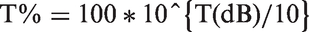
The percentage of reflection R% and transmission T% can easily be calculated using the relationship

The absorption percentage, i.e. A%, can be calculated by following formula

Result and discussion
As a general principle, we know that for obtaining good reflectance the EMSE value of 0 dB indicates 100 % reflection, meaning material is fully metallic. The value approaching away from 0 indicates that the reflection rate of material is decreasing. There is reverse condition for transmittance performance, i.e. 0 dB indicates the material is allowing 100% transmission exhibiting no shielding properties. The value away from 0 dB indicates good EMSE in terms of transmission.
The EMS performance of all five 3D structures, in both vertical and horizontal planes, was analyzed and the results demonstrated in Figures 3 to 8 comparatively. The measurements were done at incident frequencies between 8.2 and 12.4 frequency range. It was observed that “A” series fabric having 100% cotton yarn has poor EMSE in terms of reflectance and transmittance parameter in both the planes, confirming that insulating material is not suitable for shielding against EMR [10].
Electromagnetic shielding effectiveness (S11 and S21) of A series in vertical plane.
In fabric samples of B and C series, it was observed that reflectance (S11) decreases with increasing incident frequency, hence can be predicted that when the frequency increases the wavelength becomes shorter and incident waves are able to penetrate through the pores of fabric [25]. In terms of transmittance (S21) parameter, EMSE increases obviously due to reflectance, and a decline in shielding effectiveness up to 11 GHz, but thereafter the shielding effectiveness increases in spite of the fact that the shorter waves easily penetrated the fabric pores. The loss of intensity of waves is due to absorption phenomenon, hence EMSE increases between frequency range 11 GHz and 12.2 GHz. This indicates that 3D multilayer is effective in the higher frequency range.
Analysis of EMSE (S11 and S21) of 3D structures in vertical plane
The EMSE, performance in terms of S11 and S21 parameters of all five structures and three series was analyzed in the vertical plane and reported in Figures 3–5. As shown in Figure 3, the performance of A series, containing 100% cotton yarn, exhibited poor EMSE performance in both reflection and transmittance parameters. As expected, no shielding effectiveness was obtained with pure cotton fabric [2,13]. However, this series was treated as a reference sample for a comparative study with the other two series.
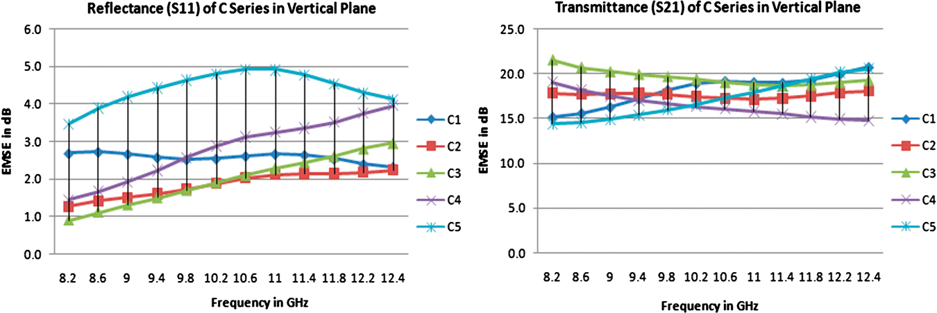
Electromagnetic shielding effectiveness (S11 and S21) of B series in vertical plane. Electromagnetic shielding effectiveness (S11 and S21) of C series in vertical plane.
In [B] series, the presence of copper hybrid yarn in weft exhibited good EMSE in terms of reflectance and transmittance behavior in vertical polarization as shown in Figure 4. The reflectance parameter followed a general trend that the reflectance performance decreases with increasing frequency indicating that at higher frequency ranges the wavelength becomes shorter and can easily penetrate through the fabric pores. As reported in Figure 4, it is quite clear that the angle interlocks and cell-type spacer fabric exhibited very good reflectance value, but with same fabric parameters contour and orthogonal fabric showed comparatively lower reflectance among all five 3D fabrics. The least reflectance value of contour fabric was due to its composition of warp-faced twill, the floating cotton warp is suppressing the hybrid weft, hence allowing the penetration of electromagnetic rays. The cell-type spacer fabric has plain order of interlacement allowing exposure of conductive hybrid yarn at regular interval. The lower reflectance of orthogonal structure was due to the formation of prominent fabric pores by binder warp, which runs through thickness from top to bottom of fabric integrating all the layers produced due to interlacement of layering warp and hybrid weft.
The transmittance parameters (S21) in the vertical plane of all five D structures in B series are also shown in Figure 4. The transmittance parameter exhibited different trend; with the increase in frequency the transmittance performance decreases and was found lowest between 10.6 and 11 GHz and starts increasing between 11 GHz and 12.4 GHz frequency range. Cell-type spacer exhibited significant increasing peak while other four structures showed a marginal increase to stagnant peak. The cell-type spacer fabric with an inclined middle layer structure with corresponding face and back layers has offered better exposure of each layer to the incident EM rays with more covered fabric pores, and hence showed maximum EMSE among all five structures. The Multi-tubular spacer fabric also provides three separate layers followed by the union of all layers. This united layer also offers layer-to-layer exposure, but not at an angular configuration which offers better covered fabric pores in case of cell-type spacer structure, hence lesser EMSE was observed in multi tubular spacer but still better results than angle interlock, orthogonal & contour structures.
The EMSE performance of C series fabrics is shown in Figure 5. The S11 parameter in vertical plane showed a differential trend. The reflectance properties of angle interlock, cell-type spacer, and multi-tubular spacer has shown decreasing reflectance value with increasing frequency and was found to be consistent with the theoretical arguments. An interesting curve was obtained in orthogonal and contour structures as shown in Figure 5. In orthogonal structure, there was improvement with an increase in frequency from 8.2 GHz to 9.4 GHz, remained stationary after that up to 11.4 GHz, and marginal improvement in reflectance property after that. In contour structure, there is a decline in reflectance property from 8.2 GHz to 11 GHz and substantial improvement with increasing frequency range from 11 GHz to 12.4 GHz. In spacer structures, the one-third hybrid yarn, which was used in face layer of fabric in both cell-type and multi tubular spacer samples, the cell-type spacer fabric has shown the best results among all five 3D structures due to better exposure of each layer to the incident EM rays. Multi-tubular spacer fabric showed least EMSE among all structures as shown in Figure 5, which showed a decline in transmittance property with increasing frequency indicating that with the adoption of hybrid yarn in warp the pores have opened up. The orthogonal structure has shown better results in vertical direction next to cell-type structure. This effect is due to the conductive yarn used in binder warp. The through-thickness movement of binder warp has offered reflection phenomenon on the surface and acted as additional conductive filler during its movement in through-thickness direction, and hence more absorption of electromagnetic waves. The same trend was observed in angle-interlock structure as the angular interlacement pattern enhanced the amount of conductivity in layers.
During the EMSE analysis of the contour structure in terms of its transmission values ,it was observed that, in the C series presence of conductive hybrid yarn shows better EMSE values as compared to the B series fabric. The transmittance increases with increase in frequency indicating that the absorption phenomenon played a dominant role in achieving EMSE.
Analysis of EMSE (S11 and S21) of 3D structures in horizontal plane
As shown in Figure 6, EMSE performance of “A” series followed the same trend as was reported in vertical direction in both reflection and transmittance parameters. The EMSE of fabric samples, woven with hybrid yarn in weft direction [B series], showed excellent performance in both reflectance and transmittance properties when fabric was tested in vertical polarization of EM wave. However, in horizontal plane very poor EMSE in terms of both S11 and S21 was reported, as shown in Figure 7. This adverse trend with similar fabric parameters was also reported by some researchers when fabric was tested in horizontal plane [16]. Both [A] and [B] series exhibited almost similar trends showing that in the horizontal plane, the presence of copper-based hybrid yarn in weft direction has absolutely no impact on EMSE performances. In C series, better reflectance values in angle-interlock, cell-type spacer, multi-tubular spacer, and contour fabric were observed in comparison with vertical plane. Orthogonal structure has produced least reflectance value due to presence of hybrid yarn in binder warp, which moves through the thickness to integrate all layers. In this process, the presence of metallic hybrid yarn increases the pores due to its rigid configuration. It is quite evident that apart from metallic content, reflectance performance is also influenced by the structural configuration of 3D fabrics and the directional disposition of EM wave on the fabric sample. However, the reflectance property decreases with increasing frequency and was observed in all five structures.
Electromagnetic shielding effectiveness (S11 and S21) of A series in horizontal plane. Electromagnetic shielding effectiveness (S11 and S21) of B series in horizontal plane. Electromagnetic shielding effectiveness (S11 and S21) of C series in horizontal plane.


In C series, transmittance value in both horizontal and vertical direction was remarkable. The presence of hybrid in both warp and weft is able to shield parallel and perpendicular EM waves. In horizontal direction orthogonal and tubular contour showed best overall EMS in both directions. The through-thickness movement of conductive binder warp yarn in orthogonal structure has acted as conductive filler and floating weave of contour structure with presence of conductive hybrid yarn in warp has facilitated to achieve excellent EMS performance. Figure 8 showed that there is a decrease in EMSE with increase in frequency in 3D fabrics, except contour and angle-interlock structure where absorption is playing a dominant role.
Comparative analysis of reflectance, absorption and transmittance behavior of 3D structures of “A” and “B” series
As shown in Figures 9 and 10, the reflectance transmittance and absorption behavior of fabrics of “A” series in both vertical and horizontal plane has an absorption value between 8 and 9%. This result was due to voluminous nature and through-thickness properties of 3D fabrics. Overall transmittance is very poor hence not suitable for EM shielding. As shown in Figure 12, Fabrics of “B” series with conductive yarn in weft has shown poor transmittance in the horizontal plane but shows better absorption properties than “A” series. The absorption % of all five 3D fabric ranges from 17 to 18.5%. In vertical plane “B”series has shown remarkably good transmittance, reflection and absorption behavior as evidenced in Figure 11. The tubular contour structure shows best absorption value of 65.49% having a maximum share of overall EMS. In this structure twill weave was used. The presence of longer cotton yarn floats in warp direction has allowed the insertion of microwave but conductive weft yarn ensured effefctive shielding of absorption phenomena. The orthogonal structure has also shown better absorption values. In this case, the presence of binder warp has created more pores facilitating penetration on electromagnetic rays and due to presence of conductive yarn in different layers, the attenuation of EM rays takes place. However, best EMS was achieved by cell-type spacer followed by angle-interlock and multi-tubular spacer. In aforementioned three structures, reflectance parameter is the influencing factor for achieving excellent EMS because the apertures in the fabric are well covered up by fabric layers in the multilayer system.
Comparative reflection, absorption, and transmittance percentage of A series 3D structures in vertical plane. Comparative reflection, absorption and transmittance percentage of A series 3D structures in horizontal plane. Comparative reflection, absorption, and transmittance percentage of B series 3D structures in vertical plane. Comparative reflection, absorption, and transmittance percentage of B series 3D structures in horizontal plane.


Comparative analysis of reflectance, absorption, and transmittance behavior of 3D structures of “C” series
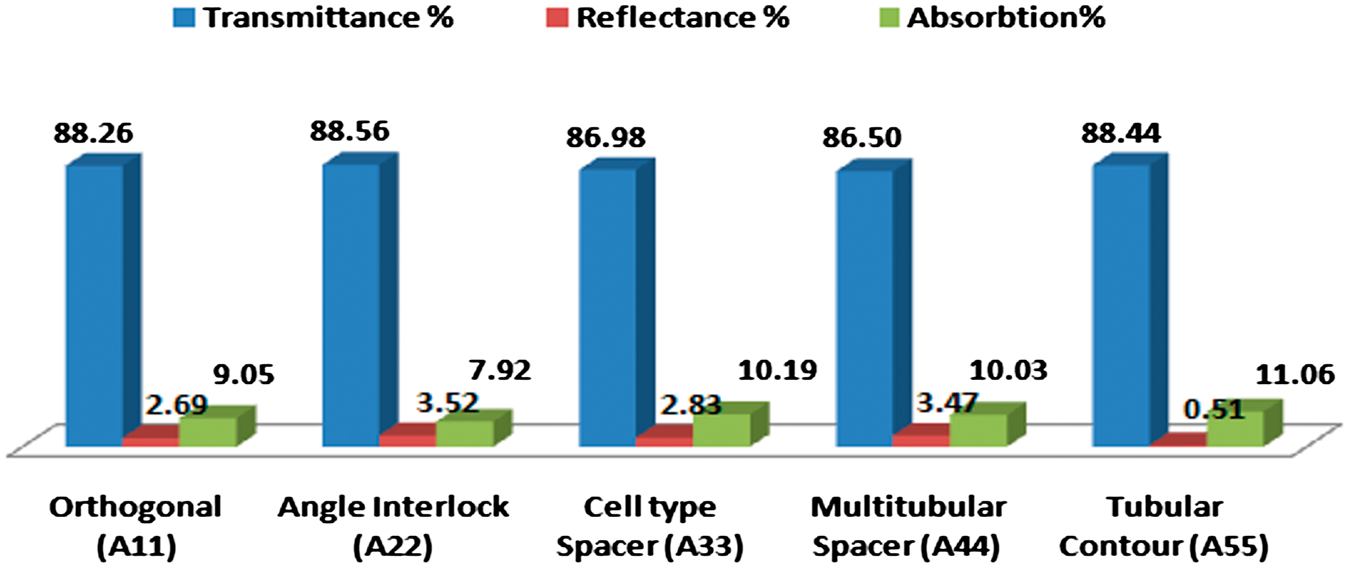
All five structures of “C” series, depicted in Figures 13 and 14, have shown excellent EMS properties in both vertical and horizontal directions. In the vertical plane, tubular contour, fabric has shown best absorption behavior following the same trend as shown in B series. The reflectance percentage has slightly increased due to the presence of one-third conductive yarn. Orthogonal structure in the horizontal plane has shown the best absorption percentage followed by tubular contour, cell-type spacer, multi-tubular spacer and least absorption values were observed in the angle interlock structure. In orthogonal structure, conducting binder warps run through thickness of fabric whereas layer warp is formed by cotton yarn which acts as an insulating material. The conductive weft and binder warp acts as a conductive filler for warp layer and enhances the absorption phenomenon. However, angle interlock cell-type spacer and multi-tubular spacer have shown better transmittance value as compared to other structures, but a major contribution was due to reflectance parameter.
Comparative reflection, absorption, and transmittance percentage of C series 3D structures in vertical plane. Comparative reflection, absorption, and transmittance percentage of C series 3D structures in horizontal plane.

EMSE with a greater share of absorption value is generally preferred. In the absorption process EM waves are converted to heat energy which can be easily dissipated out from the shielding material. The greater reflectance value would shield the material from EM waves, but the surrounding area will be adversely affected due to reflection of EM radiations.
Conclusion
In this study, a comprehensive analysis of the EMS characteristics of customized multilayer 3D conducting fabrics, using cotton/copper wrapped hybrid yarn, in “X” band frequency region, was carried out. For this, the effects of five different structural configurations in three different series and the effect of vertical and horizontal polarization of electromagnetic rays on EMSE were evaluated.
The test results revealed that all five 3D fabric having 100% cotton yarn (A Series) have poor EMSE in terms of reflectance and transmittance parameter in both planes, confirming that insulating material is not suitable for shielding against EMR.
In fabric samples having conductive hybrid in weft (B series) or both warp and weft (C series), it was observed that reflectance (S11) decreases with increasing incident frequency, hence can be predicted that when the frequency increases the wavelength becomes shorter and incident waves were able to penetrate through the pores of fabric). In terms of transmittance (S21) parameter EMSE increases, which is obviously due to reflectance, here a decline in shielding effectiveness was observed up to 11 GHz, but in some fabric the shielding effectiveness increases thereafter from 11 GHz to 12.2 GHz, in spite of the fact that the shorter waves easily penetrated the fabric pores indicating the loss of intensity of waves due to absorption phenomenon. Hence, EMSE increases between frequency range 11 GHz and 12.2 GHz.
The structural configurations of 3D structure have a remarkable influence on EMSE. The difference between the EMSE values in vertical and horizontal planes of fabrics having conductive hybrid yarn in weft direction (B series) was significant, exhibiting better results in the vertical plane than in the horizontal plane. Fabric containing conductive hybrid yarn in both warp and weft (C series) exhibited consistent EMSE in both planes. In the vertical plane tubular contour fabric has shown best absorption behavior and least in the case of the angle-interlock structure. Orthogonal structure in the horizontal plane has shown the best absorption percentage and least absorption value were observed in the angle-interlock structure. However, angle-interlock cell-type spacer and multi-tubular spacer have shown better transmittance value as compared to other structures, but a major contribution was due to reflectance parameter. It is noteworthy to mention that the enhanced absorption behavior of some of the 3D structure reported have prominent applications in radar navigation, preventing detection of objects in order to shield the enemy’s detection signal, stealth technology in military combat, and many other fields. The future research can concentrate on incorporation of different proportion of microwave absorbers in the multilayer system to enhance absorption properties.
Footnotes
Declaration of conflicting interests
The author(s) declared no potential conflicts of interest with respect to the research, authorship, and/or publication of this article.
Funding
The author(s) received no financial support for the research, authorship, and/or publication of this article.