
Abstract
Drilling is a secondary material removal and usually carried out to facilitate fastening of parts together. Drilling of composite materials is not usually a problem-free process. Issues related to delamination composite laminates need to be addressed because it introduces the stress concentration point on the composite. This study focussed on the influence of process parameters such as spindle speed, feed rate, type of drill bits and geometry on the extend of delamination experienced by the composite during the drilling process of kenaf-glass fibre-reinforced unsaturated polyester composite, and the delamination measurements were taken under a microscope. Taguchi methods and analysis of variance were employed to find the optimal parameters. From the results, the most significant parameter was the feed rate. The minimum delamination was achieved when the feed rate was 0.05 mm/rev and spindle speed was 700r/min using both types of drill bits. The quality of the drill hole using the twist drill bit has been proven to be better than the brad drill bit.
Introduction
Due to both considerations of developing an environmentally friendly material and reducing the dependency on synthetic fibres, natural fibre reinforced composites have raised large interests among material researchers, in recent years. 1 To develop composite materials from natural fibres, plant-derived fibres are combined with polymers to manufacture eco-friendly materials. 2 Material scientists have triggered big interest in exploring nonpetroleum fibres resources 3 to obtain nonabrasive materials with minimum energy consumption. Added to that, using natural fibres will generate rural/agriculture-based economy income. Furthermore, because of their significant other characteristics such as low density and cost, availability, biodegradability, as well as good mechanical properties, that encouraged designers to use them in the aerospace and automotive industries. 4 Car manufacturers have been interested in combining natural fibre composites in both internal and external parts. This presents a number of goals for the companies to reduce the overall weight of vehicles, to improve fuel efficiency and to improve the sustainability of their manufacturing process. 5 Compared with milling, turning, etc., the drilling process is largely used in composite materials and it is not usually problem-free, as similar as problems of holes in metals, 6 which affects composites’ integrity and surface quality, with particular reference to delamination damage generation. The technological method of composite materials drilling differs from metal drilling when connecting assemblies with screws, rivets, and bolts; this one has several tool-specific characteristics. Therewith, the composite material drilling is accompanied by the apparition of some particular defects that appears at the entrance of the hole, at the surface of the hole and at the hole issue. In addition, delamination is a major defect of the composites materials drilling processes due to the stress concentration point on the composite. 7 Generally, studying the drilling effects and methods have significant influences on the composite properties and performances, 8 such as the hole’s quality (very special criteria in the case of the composite process), the hole’s accuracy, damage of surface layers and drill life.
Natural fibre reinforced unsaturated polyester composites have been proven suitable for a variety of purposes. Natural fibres contents have a critical impact on the strength characteristics of the composite where the composite strength gets generated linearly with the increasing fibers content. Various types of natural fibres give several effects to the composite behaviour, and some natural fibres could affect oppositely to the composite strength properties. 9 Due to the great attributes and ecological attention, kenaf fibre-reinforced composites investigation has increased highly. Generally, the use of kenaf fibre-reinforced composites could help to generate employment in urban and rural areas while helping to decrease waste and contribute to the healthier environment. 10 Kenaf fibres are found in many engineering applications because of their low cost and biodegradability as well as a high percentage of cellulose. The aim of this study is to evaluate the usage of kenaf fibres for hybrid laminated with glass composites and suitable kenaf fibres content as alternatives based on certain criteria. Kenaf-glass fibre-reinforced unsaturated polyester composite has attracted researchers in investigating mechanical properties based on previous studies. 11
In the last years, due to the requirements of the material industry, there are some new challenges to build the development of products such as machining techniques. It requires the need to better understand the process of cutting with precision and efficiency. Although the near net shape process has progressed with much attention, more complex products need to be machined twice to get the required accuracy. Delamination was caused in both the entrance and exit plane pieces of work. This delamination may be associated with the core drill during entry and exit. While drilling holes in composite materials, delamination occurred. Several attempts have been made to understand the causes of delamination base on the input response and response variables such as point angle, spindle speed, feed rate, thrust force and torque. Drill geometry also will affect delamination. In industries, drilling is frequently used because of the need for component assembly in mechanical structures. 12 The drilling operation (using twist drill) is the most generally applied technique to create holes. 13 To investigate the influence of input variables which include spindle speed, feed rate, tool type, tool material and tool geometry on output variables, a lot of experiments have been carried out. 14 Delamination is a major concern during the drilling operation of the laminated composites because it reduces the laminates’ structural integrity. Added to that, it causes long-term performance deterioration such as bad assembly tolerance. 15
Composite laminates have been considered as difficult for machining that can bring low efficiency of drilling causing undesirable delamination. Therefore, it is necessary to improve the economic existing process of drilling and develop a more innovative drilling process for composite laminates. Improvement and development of the drilling process will be a benefit from a comprehensive literature review on drilling composite laminates. This study focussed on the influence of the most significant drilling parameters such as spindle speed, feed rate, type of drill bits and geometry on the extend of delamination experienced by the composite during the drilling process. Furthermore, to investigate the drilling parameters that affect whole composites' performance, life and efficiency, and give an overview of the main challenges related to the drilling of fibre -reinforced plastic composite materials. These experiments aim to study the effect of machining parameters on delamination in drilling kenaf-glass fibre reinforced unsaturated polyester (KGFRP) composites, glass fibre-reinforced unsaturated polyester (GFRP) composites, and kenaf fibre-reinforced unsaturated polyester (KFRP) composites, and to compare drilling quality between two types of drill bits. It shows that from the previous researches, 16 there are a few experiments with natural fiber-composite and not specifically with KGFRP composite to conduct the drilling experiment with different fibre content. The Taguchi method has been used to optimize and calculate the signal noise to ratio (SNRA) and to find the optimum value of parameters. The ANOVA (analysis of variance) method also has been used to find the most significant values.
Materials and Methods
Materials
There are four materials used to fabricate KGFRP which are kenaf fiber, glass fiber (E-Glass), unsaturated polyester and hardener. The unsaturated polyester used in this experiment is unsaturated polyester asapes 9509 with MEKP as the hardener for reinforcement. A mould is fabricated with a dimension of 300 mm × 200 mm × 6 mm. The KGFRP composite was fabricated using the hand lay-up technique. The kenaf-glass fiber ratio was 10:90, with unsaturated polyester resin, with keeping a percentage of fiber to polymer 40:60. The other two fabricated materials were KFRP and GFRP composite which also have been made by this method. Figure 1 shows the process of preparing the specimen. The most commonly used technique for the fabrication of fibre-reinforced composites is hand lay-up; the specimen is fabricated in stacked layers, and each layer is oriented to achieve maximum utilization of its properties. Resin is impregnated by hand into the fibre, usually accomplished by rollers, to force the resin into the fabric through rotating rollers. Composite laminates are then allowed to cure under normal atmospheric conditions and dry under for more than 7 days to reach the solid point of the composite. There are several processing steps for the hand lay-up technique which are mould preparation, gel coating, hand lay-up and then finishing. Mould is fabricated with a square profile using a 1 mm sheet plate with a dimension of 300 mm × 200 mm × 6 mm. Preparing the specimen.
Cutting operation that was used, a drill bit, to cut a circular hole across the section in the solid material is called drilling. There are many processes used for drilling GFRP such as conventional drilling, drilling assisted by vibrations and ultrasonic-assisted drilling to obtain the required accuracy and maintain the integrity of the material. The cutting edge has a large impact on the machining process.
17
Computer numerical control (CNC) milling machine has been selected to minimize the limitation which makes it able to do repeated work with high accuracy and high precision.
18
The CNC machine programme or G-code needs to be built first before drilling the composites. Two various drill bit types (uncoated HSS twist and uncoated HSS brad) with a 6 mm diameter were used to drill the holes. Machining parameters were selected for spindle speeds of 700 r/min, 1400 r/min and 2100 r/min. Feed rates were set at 0.05 mm/rev, 0.12 mm/rev and 0.20 mm/rev. Before the drilling process begins, the fabricated composite had been cut into the specimen size dimension of 140 mm × 60 mm × 6 mm as illustrated in Figure 2. Based on the 27th Edition Machinery Handbook on the topic limits and fits, clearance fits and limits for cylindrical parts for the hole or shaft apply in American and British standards. Referring to American National Standard Preferred Hole Basis Metric Clearance Fits (ANSI B4.2 1978 (R1999)), the basic size for no-go pin gauge used is 6 mm H7 (hole) with a maximum tolerance of 6.012 mm and a minimum tolerance of 6.000 mm. The most common test used to measure hole diameter is using no-go pin gauge test. The use of this fixed limit gauge is the simplest form of pass/fail attribute inspection. If the go fits and the no-go not, the hole is considered intolerant and as passed. When inspecting a cylindrical hole, if the go does not enter, the hole is too small (undersize) and fails. If the no-go enters, the hole is considered too large (oversize) and also fails. Cutting and drilling process.
Selected spindle speed and feed rate.

The drilled holes on the specimen were inspected and measured by the tool maker microscope with Motic Image Plus software. Figure 3 below illustrates inspection through the microscope, and Fd (the delamination factor) is calculated as a measure of delamination damage Inspection of delamination using a microscope.

The two different types of drill bits, as shown in Figure 4, used are twist drill and brad drill. Both drills are 6 mm diameters. Brad drill has a specific point geometry causing the fibres tensioning prior to cutting thus enabling a ‘clean-cut’ of the fibres. As a consequence, machined surfaces are smoother. The helix profile was maintained in order to compare the cutting performance of the drill with the twist or brad drill. The drilled hole’s quality is determined by using no-go pin gauge (6 mm) with 6.012 mm maximum tolerance and 6.000 mm minimum tolerance. This is to measure the hole oversize in terms of drilled hole quality. Types of drill bits: (a) Twist drill bit and (b) brad drill it.
After all experiments have been done, Taguchi analysis (for three parameters (material, spindle speed and feed rate and three levels)) is used to analyse orthogonal arrays experiments which give much-reduced variance for the experiment with optimum settings of control parameters.
From the results of the experiment, SNRA values were calculated for each level/factor. The most suitable SNRA was calculated using the condition ‘the smaller the better’
Consequently, ANOVA was conducted to obtain the factor that has the greatest influence in machining parameters.
Results and Discussion
After drilling experiments were performed, it was necessary to assess the damage inspection of machining damage, using the microscope and image analysis software to measure the extent delamination size, as shown in Figures 5 and 6. Measurement specimen for the twist drill bit. Measurement specimen for the brad drill bit.

Dmax value (entry and exit) for the twist drill bit.

GFRP: Glass fiber reinforced unsaturated polyester, KFRP: Kenaf fiber reinforced unsaturated polyester, KGFRP: Kenaf glass fiber reinforced unsaturated polyester.
Dmax value (entry and exit) for the twist drill bit.

GFRP: Glass fiber reinforced unsaturated polyester, KFRP: Kenaf fiber reinforced unsaturated polyester, KGFRP: Kenaf glass fiber reinforced unsaturated polyester.
The highest Dmax for exit (brad drill bit) is from experiment number 27 (24.138 mm) with feed rate 0.20 mm/rev and spindle speed 2100 r/min followed by experiment number 18 (24.033 mm) with feed rate 0.20 mm/rev and spindle speed 2100 r/min and the third is experiment number 26 (23.687 mm) with feed rate 0.12 mm/rev and spindle speed 2100 r/min. The lowest value of the maximum diameter is from experiment number 10 (7.410 mm) with 0.05 mm/rev feed rate and 700 r/min spindle speed.
Delamination Factor
Entry and exit Fd (delamination factor) for the twist drill bit.
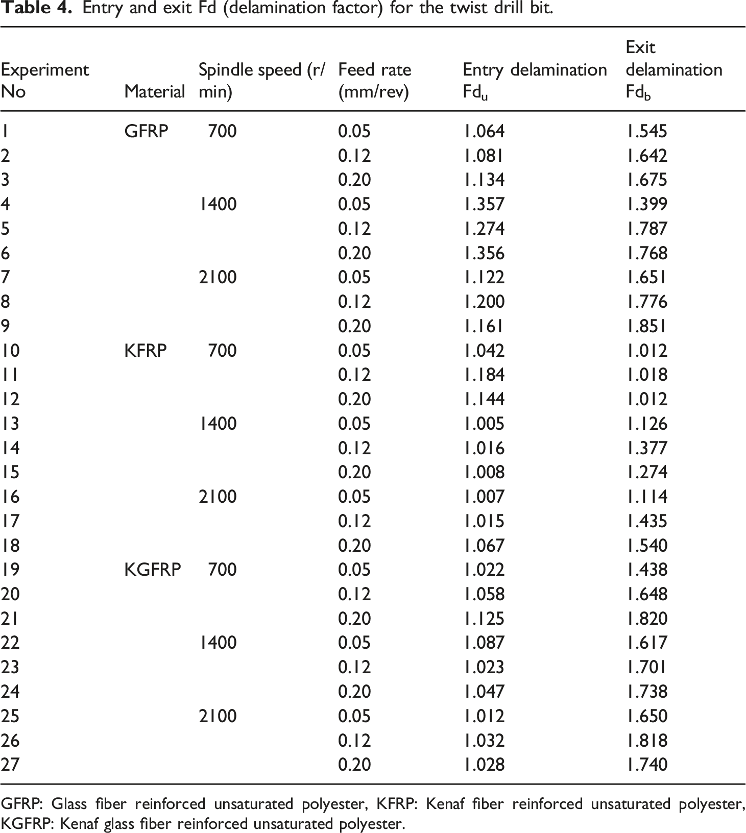
GFRP: Glass fiber reinforced unsaturated polyester, KFRP: Kenaf fiber reinforced unsaturated polyester, KGFRP: Kenaf glass fiber reinforced unsaturated polyester.
Entry and exit delamination factor (Fd) for the brad drill bit.

GFRP: Glass fiber reinforced unsaturated polyester, KFRP: Kenaf fiber reinforced unsaturated polyester, KGFRP: Kenaf glass fiber reinforced unsaturated polyester.
The suitable drilling composites technique.

GFRP: Glass fiber reinforced unsaturated polyester, KFRP: Kenaf fiber reinforced unsaturated polyester, KGFRP: Kenaf-glass fiber reinforced unsaturated polyester.
Main Effects Plot for SNRA
After calculating delamination factors (Table 4 for the twist drill bit and Table 5 for the brad drill bit), the next step is to compute the SNRA. SNRA for each datum was calculated by applying equation (2). The SNRA response graph for twist-entry delamination and twist-exit delamination is shown in Figure 7 (a) and (b). A greater SNRA corresponds to a better performance, the factor level with the highest SNRA is the optimum level.
19
Therefore, the optimum parameters combination level identified for the present experiment in the drilling process for Twist-Entry is KGFRP with spindle speed at 2100 r/min and feed rate at 0.05 mm/rev. Meanwhile at Twist-Exit, the optimal parameters combination level was KFRP with spindle speed at 700 r/min and feed rate at 0.05 mm/rev. (a) Main effects plot for SNRA (Twist-Entry), (b) main effects plot for SNRA (Twist-Exit).
Based on graph at Figure 8 (a) for drilling process using the brad drill bit, the optimal machining parameters for Brad-Entry is KGFRP with spindle speed at 1400 r/min and feed rate at 0.05 mm/rev. Figure 8 (b) shows GFRP, spindle speed at 700 r/min and feed rate at 0.05 mm/rev are the optimal value for Brad-Exit. (a) Main effects plot for SNRA (Brad-Entry), (b) main effects plot for SNRA (Brad-Exit).
ANOVA for SNRA
ANOVA for SNRA (twist-entry).
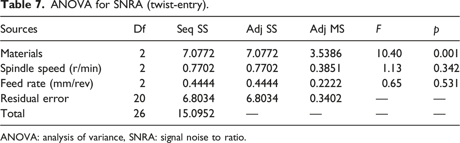
ANOVA: analysis of variance, SNRA: signal noise to ratio.
ANOVA for SNRA (twist-exit).

ANOVA: analysis of variance, SNRA: signal noise to ratio.
ANOVA for SNRA (brad-entry).

ANOVA for SNRA (brad-exit).

ANOVA: analysis of variance, SNRA: signal noise to ratio.
Drilled Hole Quality Comparison
Figures 9 and 10 show the delamination factor versus drilled hole in term comparing using two types of drill bits at entry and exit of the specimen. From the results, we can observe the plotted graph of 135 holes for entry delamination, lower delamination and overall delamination between the twist and brad drill bit. The orange line represents delamination of the drilled hole by the brad drill bit; meanwhile, the blue line represents delamination of the drilled hole by the twist drill bit. Based on all graphs, the value of delamination made by the brad drill bit is higher compared to the value of delamination made by the twist drill bit.
21
This is particularly noticeable at the exit of the delamination made by the brad drill bit. It is clearly shown that the drilling process by the twist drill bit is better than the brad drill bit. In another word, it can be observed that, the hole made by the twist drill bit (blue) has the lowest delamination factor than the brad drill bit for overall. Entry delamination: twist versus brad. Exit delamination: twist versus brad.

All specimens also have been tested by the no-go pin gauge test to measure the quality of the drilled hole. 74% from 135 drilled holes made by the twist drill bit is fit and 91% from 135 drilled holes made by the brad drill bit is not fit. Figure 11 illustrate a summary of the no-go specimen test for twist drill bit analysis out of the 135 drilled holes. 100 drilled holes or 74% met the required standard while the rest were found to have not met the standard requirement or the drilled holes being oversize. Based on Figure 12, only 8% or 11 drilled holes meet the requirement, 91% or 123 drilled holes are not fit for the requirement and 1% drilled holes are oversize. By comparing these two graphs, observation can be made that drilled holes made by the twist drill bit have more quality than made by the brad drill bit. The size of the hole is a very important factor because of the close tolerance between the fastener and hole during assembly.
22
It is clearly shown from Figure 12 that the drilled hole by using a twist drill bit is of more quality and produces the most dimensionally accurate one. It produces a hole with a diameter that is close to the nominal diameter. Compared to Figure 12, drill holes made by brad drills (91%) are not fit. It may happen because of the peeling, fiber pullout,23,24 protruded fibers, incomplete removal of the fibers in the existing side, or burrs inside the hole.
25
No-go specimen test (twist drill bit). No-go specimen test (brad drill bit).

Conclusions
Based on the findings, the delamination at the entry and exit specimen of GFRP, KFRP and KGFRP have been measured and following conclusions can be drawn from this experiment: - Feed rate, tool material and cutting speed are the most influential factors in delamination. Thus, hard tool materials and lower feed rates can reduce delamination drilling GFRP. - The optimal value of the machining parameters is feed rate. Based on the SNRA, the lowest feed rate and lowest spindle speed have the lowest value of the delamination factor. - Both spindle speed and the feed rate have the highest influence on the delamination damage of the specimen. - The results of ANOVA revealed the most significant value of the machining parameters, and also feed rate. The damage increases with an increase in both machining parameters, and it means that the composite damage is bigger for high feed rate and higher spindle speed. - The delamination factor made by the twist drill bit showed a superior result, and it means the twist drill bit produces less delamination at the GFRP, KFRP and KGFRP composite (entry and exit) than the brad drill bit. - The quality of drilled holes made by the twist drill bit has met the requirements higher than using the brad drill bit.
Footnotes
Acknowledgments
Authors would like to thank the Ministry of Higher Education and Scientific Research/Iraq and to Mustansiriyah University, College of Engineering/Mechanical Engineering Department, for their scientific assistance. Appreciation also extends to all technicians working in the Mechanical Department Laboratory/UPM, for their support. Further appreciate goes to Facilities Maintenance Engineering team, UniKL Malaysian Institute of Industrial Technology (MITEC), for supporting.
Declaration of conflicting interests
The author(s) declared no potential conflicts of interest with respect to the research, authorship, and/or publication of this article.
Funding
The author(s) received no financial support for the research, authorship, and/or publication of this article.