
Abstract
This article investigated the effect of wire electrical discharge machining process parameters such as pulse on time, pulse off time, pulse current and the wire drum speed on the material removal rate, while machining newly developed hybrid metal matrix composite (Al7075/7.5%SiC/7.5%Al2O3). The hybrid composite was prepared by inert gas–assisted electromagnetic stir casting process. Taguchi method was used for parameter optimization and the level of importance was determined using analysis of variance. The results showed that pulse on time, pulse off time and pulse current were significant parameters. The pulse on time was the most significant parameter that contributed maximum (46.04%) to the material removal rate followed by pulse current (34.72%), pulse off time (10.23%) and interaction, pulse on time × pulse off time (5.46%). The wire drum speed had insignificant effect on the material removal rate. In confirmation test, the average experimental value of material removal rate was within the predicted optimum class interval.
Keywords
Introduction
Industrial technology progress especially in aerospace applications and the manufacturing sector introduces a variety of new materials having superior mechanical characteristics. Metal matrix composites (MMCs) are known for their high strength-to-weight ratio, high hardness and wear resistance. Carbide ceramic materials are known for their hardness and wear resistance properties making them useful materials for cutting tools and dies. Processing of these materials using traditional techniques is difficult due to high tool wear and tooling cost. 1 In machining the MMCs, the difficulty arises due to abrasive nature of reinforcement particulates or high hardness and wear resistance in the case of tungsten carbide (WC). The noncontact material removing process such as wire electrical discharge machining (WEDM) is a versatile and useful technological process for machining such materials. 2 There is no direct contact occurring between the wire electrode and the workpiece. So no stress is created in the processed material. The material is removed by spark erosion process. The performance measures in WEDM are material removal rate (MRR), surface roughness (SR) and the kerf width. Among these, the most important performance measure is MRR, which determines the economy of machining and rate of production. The SR of machined surface indicates the quality of product and kerf, that is, cutting width determines the dimensional accuracy of the finished parts. The internal corner radius to be produced in WEDM operations is also limited by the kerf. The detail of kerf produced in WEDM is shown in Figure 1.
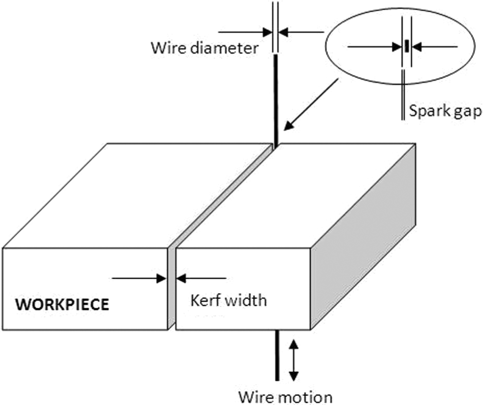
Details of kerf width in WEDM.
The kerf is calculated by summing up the “wire diameter to 2 × wire–workpiece gap distance.” The wire–workpiece gap usually ranges from 0.025 to 0.075 mm and is constantly maintained by a computer-controlled positioning system. 3 The MRR is calculated using the formula as 4 MRR (mm3/min) = kerf width (µm) 10−3× specimen thickness (mm) × length of cut (mm)/machining time (s) 1/60.
Literature survey
Liao et al. optimized the WEDM process parameter for SKD11 alloy steel using Taguchi method. A total of six parameters at three levels were chosen in L18 orthogonal array (OA). The study concluded that table feed and pulse on time were the significant parameters for MRR. The larger feed and pulse on time resulted in higher MRR. 4 Guo et al. studied the effect of WEDM process parameters for A6061/20%Al2O3 composite using L16 array. The investigation of the study revealed that an increase in voltage and current increased the machining rate of ordinary steel and the composite. The rank of significance of four factors was the pulse on time, voltage, machining current and pulse interval. The cutting rate increased with an increase in pulse duration. 5 Tosun et al. investigated the effect of WEDM machining parameters such as pulse duration, open-circuit voltage (OCV), wire speed and dielectric flushing pressure on the kerf and the MRR while machining AISI 4140 steel. Based on analysis of variance (ANOVA) method, the highly effective parameters on the MRR were OCV and pulse duration. The wire speed and dielectric flushing pressure were less effective factors. The results showed that OCV contributed 78.67% and the second-order ranking factor (pulse duration) contributed 12.76% to the MRR. An increase in OCV and pulse duration increased the MRR. 3 Mahapatra and Patnaik studied the factors and their interactions both for maximization of MRR and minimization of SR for D2 steel in WEDM process using Taguchi method. The analysis showed that factors such as discharge current (A), pulse duration (B), dielectric flow rate (F) and interactions A × B and A × F have been found to play significant role in cutting operations. The results of confirmation experiment agreed well with a prediction error of 4.062% with MRR and 1.53% with SR. 6 Ramakrishnan and Karunamoorthy developed artificial neural network (ANN) model and multi-response optimization technique to predict and select the best cutting parameters of WEDM. Inconel 718 was selected as work material to conduct experiment according to Taguchi L9 OA. ANOVA was used to identify the level of importance of machining parameters. The study concluded that increasing the pulse on time and ignition current, the MRR was improved. The increase in delay time reduced the MRR considerably. 7 Patil and Brahmankar analyzed the effect of WEDM process parameters on MRR for Al/SiC composite using response surface methodology (RSM). The various thermo-physical properties such as thermal conductivity, electrical conductivity, density, specific heat, melting temperature, thermal expansion coefficient and latent heat of fusion were considered along with machining process parameters. The experimental results showed that an increase in percentage of reinforcement particulates in MMCs decreased MRR. The decrease in MRR was almost 12% with an increase of 10% reinforcement particulates. The model suggests that pulse on time and thermo-physical properties such as thermal expansion coefficient, thermal diffusion and melting point are significant parameters on MRR. 8 Shah et al. investigated the effect of seven different WEDM process parameters on the machining responses such as the MRR, kerf and SR while machining WC samples using Taguchi method. The results concluded that the MRR increases with larger values of open voltage and pulse on time but decreased with an increase in material thickness, pulse off time and servo voltage. The results of ANOVA showed that pulse on time was the most significant factor to the MRR contributing 32.06%. The contributions from other significant factors such as open voltage, servo voltage and pulse off time were 20.03%, 19.73% and 8.71%, respectively. 9 Jangra et al. studied the effect of WEDM process parameters on MRR and SR for tungsten carbide–cobalt (WC-Co) composite. The simultaneous optimization of MRR and SR was carried out using gray relational grade and Taguchi method. ANOVA showed that taper angle was the most significant parameters contributing 54.95% to MRR followed by pulse on time and pulse off time contributing 21.76% and 20.68%, respectively. The percentage error between experimental and predicted results for MRR was less than 4% with individual characteristic optimization. 10 Satishkumar et al. investigated the effect of WEDM process parameters on MRR and SR for Al6061 with 5%–15% of SiC composite using L9 OA. The results showed that MRR decreased with an increase in volume fraction of SiC. Gap voltage was the most significant parameter contributing 92.13% to MRR while machining 15% vol SiC/Al6061 composite. The contributions by pulse on and wire feed were 4.89% and 2.65%, respectively. The response graph of MRR showed that increasing the wire feed improved MRR for higher volume fraction of reinforcement. However, pulse off time was not a significant factor, but lower value of it resulted in higher MRR. Also, the maximum variation of 7.5% was observed for MRR in experimental and predicted values obtained by the regression equation. 11 Yang et al. analyzed the variations in MRR, roughness average and the corner deviation (CD) depending on parameters of WEDM process in relation to the cutting of pure tungsten profiles. The analysis showed that pulse on time was the most significant factor contributing 70.66% to the MRR. The contribution from pulse off time and servo voltage was 13.04 and 5.17%, respectively. MRR increased with an increase in pulse on time when similar pulse off time is used but decreased with an increase in pulse off time for a constant pulse on time. 12
In the literature, few works have been reported regarding the machining of composites. The objective of this work is to optimize the MRR machining parameters of WEDM while machining newly developed Al7075/SiC/Al2O3 hybrid composite. The investigated machining parameters are pulse on time, pulse off time, pulse current and wire drum speed. ANOVA was used as the analytical tool in studying the effects of these machining parameters and their interaction effects. Also, the machined surfaces of hybrid composites were analyzed using scanning electron microscope (SEM) analysis.
Experimental procedure
Preparation of hybrid composite
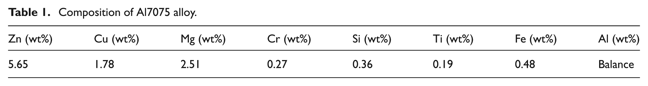
In this study, the material employed is cast hybrid MMC fabricated using electromagnetic stir casting process. The photographic view of the setup is shown in Figure 2. The hybrid composite consists of 15 wt% Al2O3 and SiC particulates (7.5% each) in metal matrix Al7075 alloy. The Al alloy of 7xxx series has a great potential to be utilized in aerospace and automotive industries because of its high strength-to-weight ratio and good resistance to corrosion. The weight percentage composition of 7075 Al alloy is shown in Table 1. Reinforcements SiC and Al2O3 in particulate form are used to fabricate the hybrid composite.
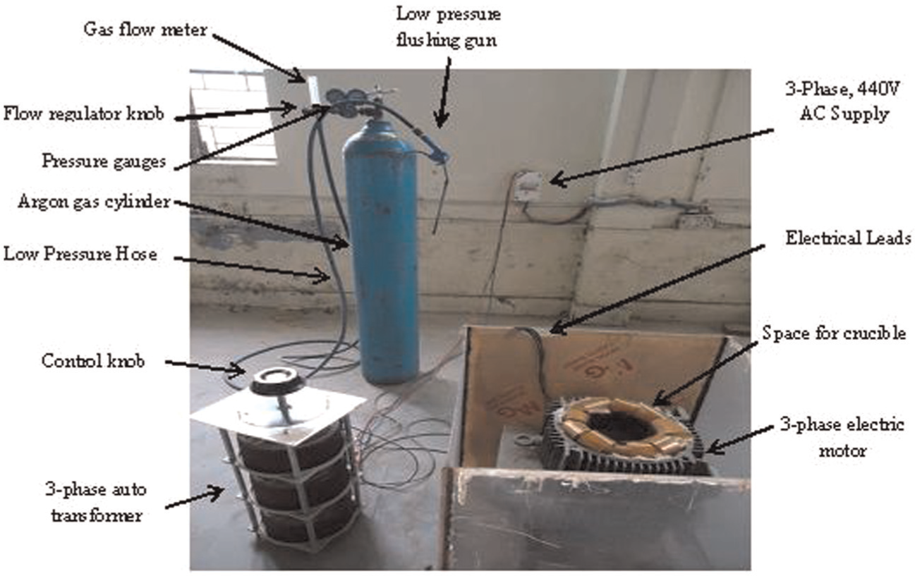
Experimental setup of inert gas–assisted electromagnetic stir casting process.
Composition of Al7075 alloy.
These reinforcements have 20–40 µm size particles and are used in combination in the ratio of 1:1. The melting of matrix metal Al7075 alloy is carried out in a graphite crucible using electric resistance heating type muffle furnace. The degassing of melt is done by inert gas (Argon) for 10 min time before introduction of reinforcement into it. Also, inert gas atmosphere is maintained above the melt surface during the synthesis of hybrid composite so as to minimize the contamination of aluminum due to atmospheric air. When melting is achieved at temperature of 715 °C, the melt is quickly lifted from the furnace and placed inside the electromagnetic stirring device. The supply is switched on and a forced vortex is generated in the melt. The preheated reinforcement (Al2O3 and SiC) particulate at a controlled rate was inducted into the melt. The reinforcement particulates (Al2O3 and SiC) were mixed thoroughly and preheated to a temperature of 900 °C before induction. After reinforcement induction phase is completed, the electromagnetic stirring is continued till melt reached the solidus state. Figure 3(a) and (b) shows the microstructure of 15 wt% Al2O3 and SiC particulates (7.5% each) in Al7075 alloy MMC cast by inert gas–assisted electromagnetic stir casting process. The reinforcement phase is found to be uniformly distributed in the metal matrix. When the hybrid composite is processed at higher temperature of melt and higher stirring speed, the clustering of particles occurs. This gives rise to porosity. Figure 3(c) shows the porosity due to clustering of particles when hybrid composite is processed at higher melt temperature and higher stirring speed.
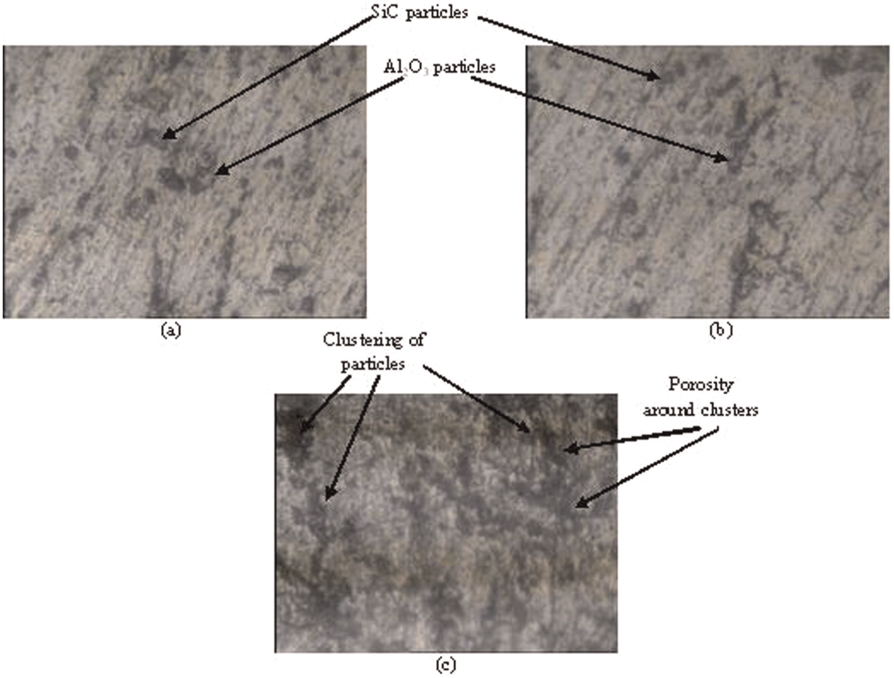
(a, b) Microstructure of hybrid MMC containing 15 wt% (Al2O3/SiC)p (7.5% each) in Al7075 alloy and (c) hybrid composite when processed at higher temperature and higher stirring speed.
Machining parameters and response
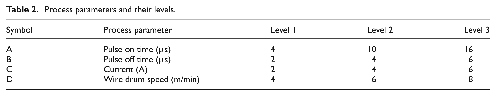
The four input process parameters, namely, pulse on time, pulse off time, pulse current and the wire drum speed were chosen as process parameters to study their effects on MRR while cutting the hybrid MMC. The pilot experiment was done with full range of machine capability for pulse on time (4–28 µs), varying in step of four units; pulse off time (1–7 µs), varying in step of one unit; pulse current (1–7 A), varying in step of one unit; and the wire drum speed (3–9 m/min), varying in step of one unit. One parameter was varied at a time while the others were maintained at their mid level. At the extreme highest value in the case of pulse on time (28 µs) and pulse current (7 A), the hybrid composite could not be machined as the WEDM machine failed to operate. Then regarding the selected range, the pilot experiment was performed and the graphs were drawn for analysis. The graph of pulse on time versus MRR showed that MRR increased with an increase in pulse on time initially at a higher rate but terminated almost in a steady state at the later stage beyond 16 µs. Similarly, for the pulse current, the MRR increased with an increase in pulse current initially, but the curve almost flattened at the later stage beyond 6 A.
With above study, it was concluded that the range for pulse on time (4–16 µs) and pulse current (2–6 A) should be chosen for this particular hybrid composite on this WEDM machine. Table 2 gives the levels of various parameters and their designations.
Process parameters and their levels.
Design of experiment using Taguchi method
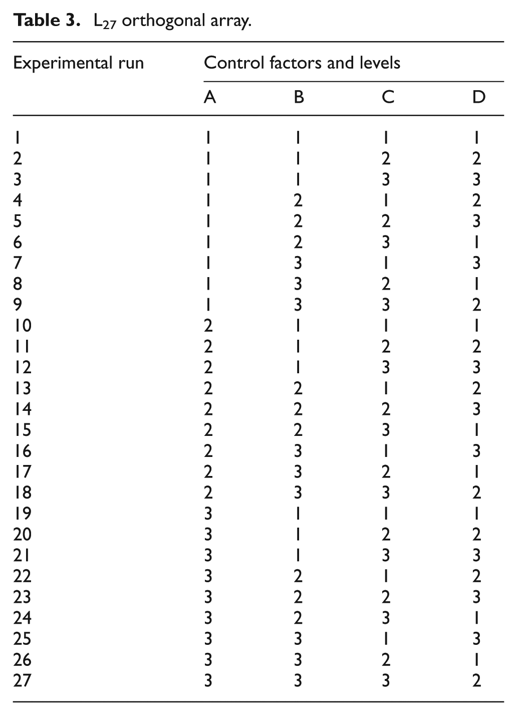
In order to get the optimum and accurate results, the design of experiments (DOEs) technique is used to collect the data. The OA forms the basis of the experimental analysis in the Taguchi method. 13 The four control parameters, that is, pulse on time (A), pulse off time (B), pulse current (C) and the wire drum speed (D) at three levels were selected in this study. L27 standard array was chosen as shown in Table 3 and MINITAB15 software was used to analyze the results.
L27 orthogonal array.
Conduct of experiment
WEDM is a spark erosion process. The sparks are generated between the workpiece and the wire electrode immersed in a dielectric fluid. The material gets removed by a series of discrete sparks taking place at the area to be machined through electro-thermal mechanism. The continuous flow of dielectric fluid flushes away the removed particles from the machined region. The response characteristic used in the study is MRR. The strength and hardness of the work materials are not factors in WEDM, but melting point of the work material is an important property. This is why WEDM finds extensive uses in machining of hard materials. The rectangular specimens of 4 mm thickness were prepared from the mid portion of the cast ingot. The length and width of specimen were 70 × 30 mm giving sufficient run for the machine to make various cuts of 10 mm length according to DOE. The top and bottom surfaces of specimen were given smooth finish using 600 grade emery papers. The wire EDM machine used was WEDM program and control system (model DK7712; Jiang Nan Saite NC, China). Molybdenum electrode wire of 0.18 mm diameter was used in this study. Deionized water was used as dielectric fluid at room temperature (30 °C). Photographic view of the wire electrical discharge machine is shown in Figure 4. After machining, the specimens were cleaned with acetone. The kerf was measured using the Focus Tool Makers Microscope (×80). The kerf values were measured at eight places spread over the entire length of cut, leaving 1 mm length at the beginning and 1 mm at the end. The specimen picture showing the kerf measurement locations in a cut is shown in Figure 5. The kerf values used in the study are the mathematical average of eight measurements made from the specimen in each cut.
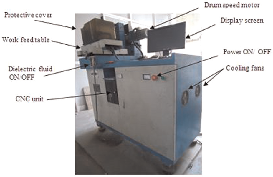
Photographic view of wire electrical discharge machine.
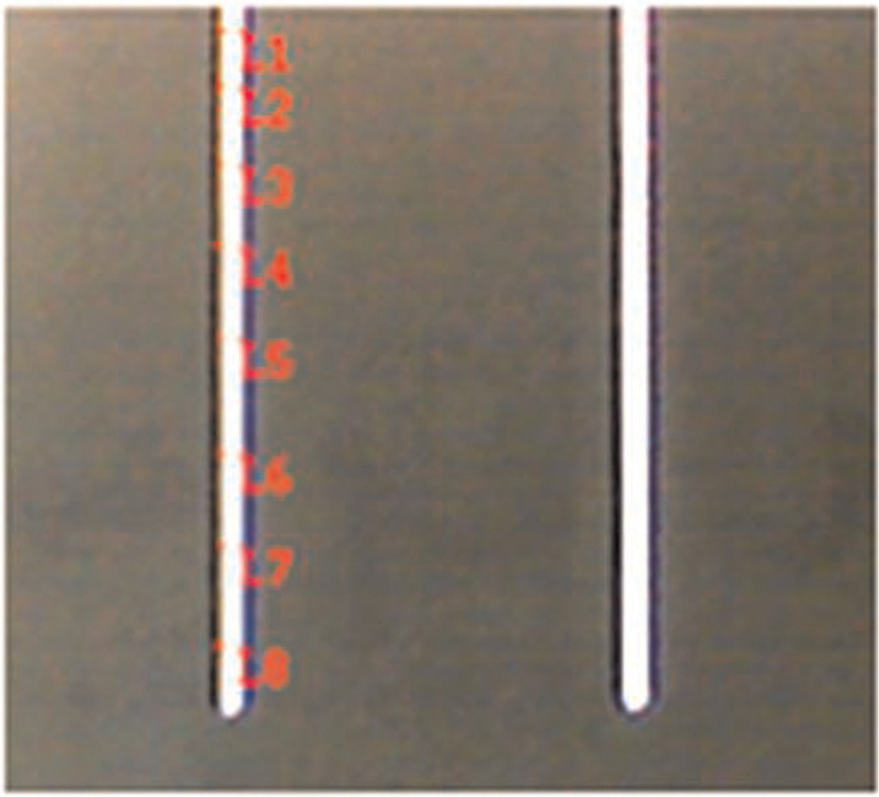
Kerf width measurements at various locations in a cut.
The microscope was interfaced with a computer and Caliper Pro 4.2 software was used for taking the kerf measurements. The cutting time for each cut length is noted from the monitor screen display. The observed average values of kerf width, machining time and calculated MRR at different levels of the WEDM process parameters are shown in Table 4.
L27 OA with kerf, machining time and MRR for hybrid composite.
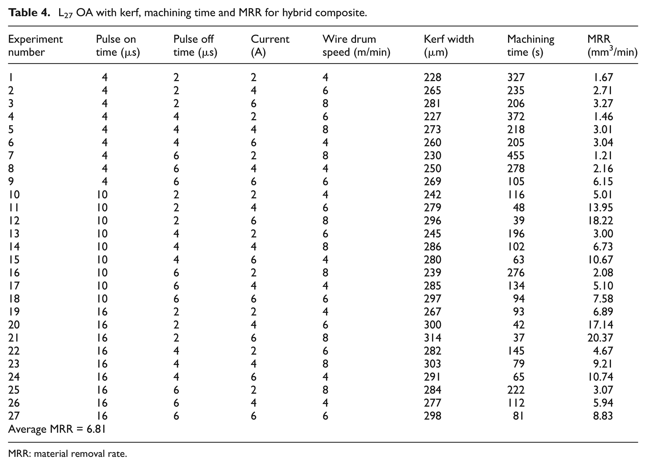
MRR: material removal rate.
Analysis of experiment
In Taguchi method parameter design, the basic method converts the objective parameter to the signal-to-noise (S/N) ratio, which is treated as the quality characteristic evaluation index. The S/N ratio is used to measure the sensitivity of the quality characteristic being investigated in a controlled manner. In Taguchi method, the term “signal” represents the desirable effect (mean) for the output characteristic and the term “noise” represents the undesirable effect (or signal disturbance) for the output characteristic, which influences the outcome due to external factors, namely, noise factors. The least variation and the optimal design are obtained by means of S/N ratio. The quality characteristic for MRR is “higher the better (HB)” selected. In Taguchi method, a loss function is defined to calculate the deviation between the experimental values and the designed values. Loss function value is further converted into S/N ratio. Minimizing quality loss is equivalent to maximizing the S/N ratio. The S/N ratio for MRR is given by the expression
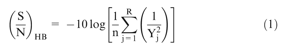
where Yj is the jth result of experiment and n is the repeated number of the jth experiment. 13
Results and discussion
The most important performance measure in WEDM, describing the production economics, is MRR while machining the parts. In order to get higher rate of production, the objective is to get highest MRR, which depends on the WEDM parameters’ setting. Improper selection of parameters may lead to serious consequences such as short circuiting of wire and wire breakages. Furthermore, the wire breakage imposes limits on cutting speed, which in turn reduces productivity.
Effect of process parameters on MRR
Table 4 shows the average values of kerf width, cutting time and MRR data. Software MINITAB15 was used to analyze the results for MRR. The analysis showed the effects of four main process parameters and their second-order interactions while machining the hybrid composite. Based on the evidence at 95% confidence level (α = 0.05), pulse on time, pulse off time and pulse current were found to have significant effect on MRR (p-value < 0.05) whereas wire drum speed did not have significant effect (p-value > 0.05). Among the interactions, only the interaction between pulse on time and pulse off time showed significant effect (p-value < 0.05). Other interactions were not statistically significant. Now the data are pooled and Table 5 shows the pooled ANOVA for MRR. The percentage contribution of each parameter is calculated. The pulse on time was the most significant parameter that contributed maximum (46.04%) to the MRR. The contribution from other parameters was pulse off time (10.23%) and pulse current (34.72%). The contribution from second-order interaction parameter (pulse on time × pulse off time) was 5.46%. The mean responses refer to the average value of the performance characteristic for each parameter at different levels. The average values of MRR for each parameter at levels 1–3 were calculated and are presented in Tables 6 and 7.
Analysis of variance for S/N ratios (MRR) after interaction and pooling.
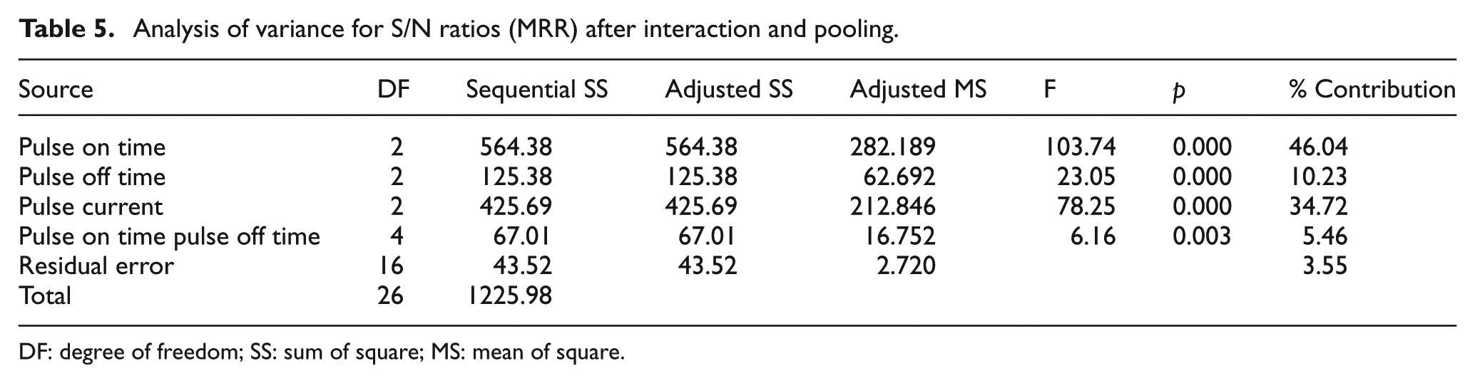
DF: degree of freedom; SS: sum of square; MS: mean of square.
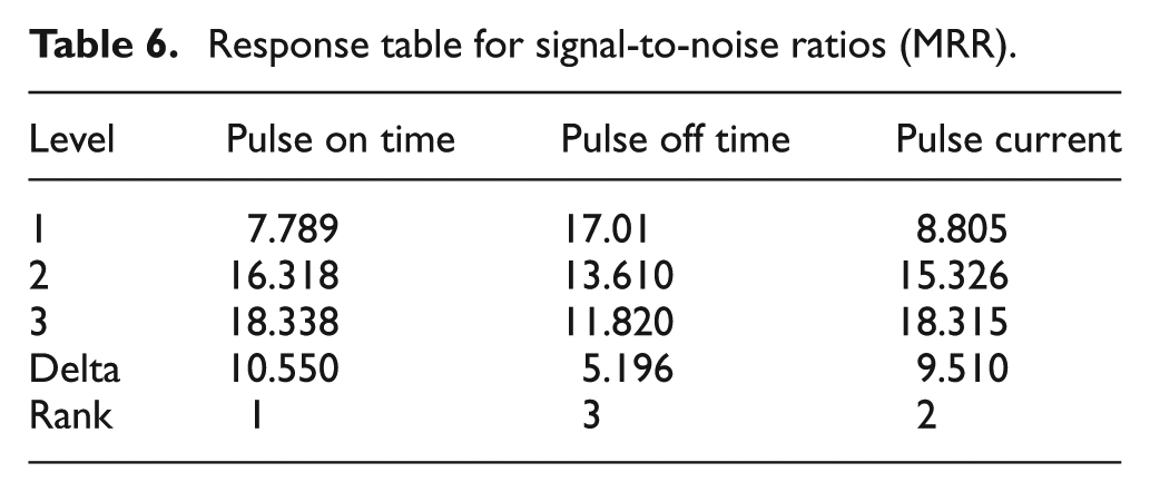
Response table for signal-to-noise ratios (MRR).
Response table for means (MRR).
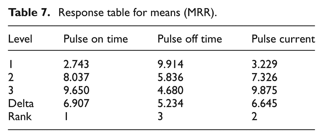
These values are plotted and shown in Figures 6 and 7. The main effects (raw data) of the various process parameters when they change from the lower to higher levels are given in Table 7 and can be visualized in Figure 6. The S/N ratio analysis suggests that the best levels for maximum value of MRR are A3, B1 and C3. The main effect plot for mean and their interaction plots are shown in Figures 7 and 8, respectively.
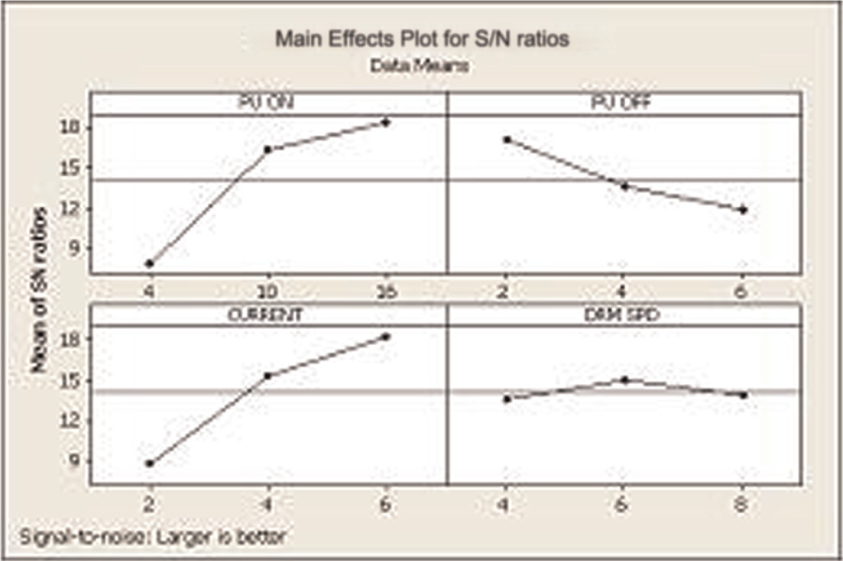
Effect of process parameters on MRR (main effects) for S/N ratio.
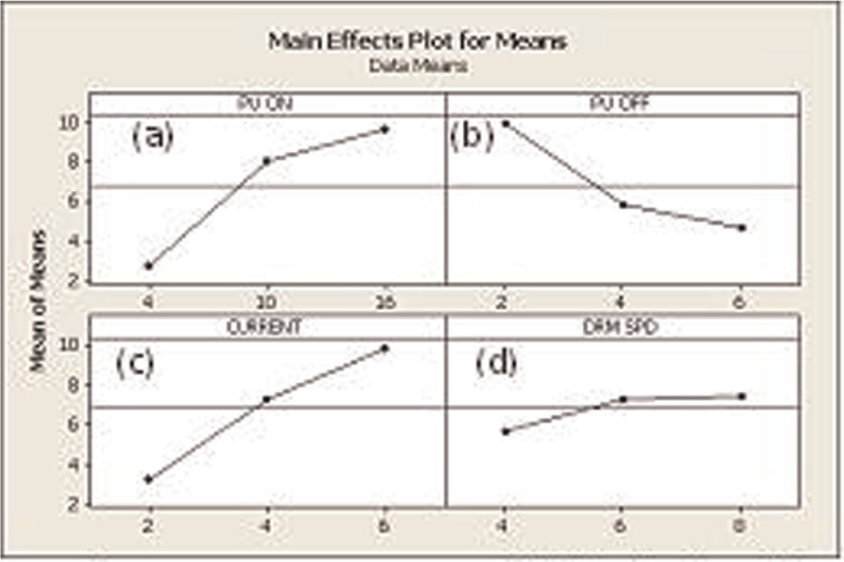
Effect of process parameters on MRR (main effects) for means.
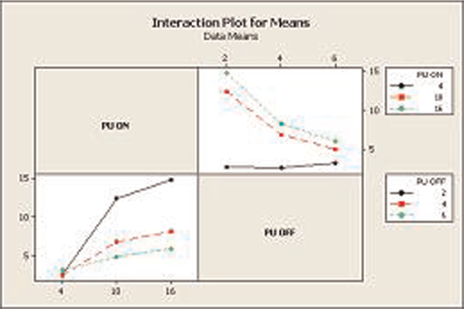
Interaction plot for means on MRR.
Effect of pulse on time on MRR
Figure 7(a) indicates the effect of pulse on time on the MRR. The MRR increases as the pulse on time increases. The influence of pulse on time on the MRR is the most significant parameter. In WEDM process, the discharge energy produces very high temperature at the point where spark strikes the surface. This causes a minute part of specimen to melt and vaporize. Increasing the pulse on time means longer spark duration, that is, more amount of discharge energy per spark reaching the surface. Because of this, large amount of material melts per spark in the gap. This increases the MRR. Thus, an increase in the pulse on time is found to increase the MRR. Hence, to obtain higher MRR, the pulse on time should be kept high. The results from this study are in agreement with other researchers.3–5,7,12
Effect of pulse off time on MRR
Figure 7(b) presents the effect of pulse off time on MRR. The MRR decreases as the pulse off time increases. This is because the less number of discharges occur for a specific period of time. Thus, larger pulse off time results in small quantity of metal melting in the gap. This produces lower MRR. The results from this study are in agreement with other researchers.7,11,12
Effect of pulse current on MRR
Figure 7(c) shows the effect of pulse current on the MRR. Pulse current is the second most significant process parameter affecting the MRR. The MRR increases as the pulse current increases. This is because the discharge energy becomes intense with an increase in the pulse current. This high-intensity spark energy produces more powerful explosion resulting in more material melting, thus higher MRR. Hence, to obtain higher MRR, the pulse current should be kept high. The results from this study are in agreement with other researchers.5–7
Effect of wire drum speed on MRR
Figure 7(d) indicates the effect of wire drum speed on the MRR. Although this is not a significant factor contributing to the MRR, the response graph trends can be explained as follows. The MRR increases as the wire drum speed increases. During machining of materials by WEDM, large amount of molten metal and the reinforcement particles (due to intense spark energy) are available in the gap as debris. The effective flushing of this debris material will add to higher MRR. The high wire drum speed helps in effective flushing of molten metal. Ineffective flushing may contaminate the gap and thicken the recast layer. Hence, MRR is higher at higher wire drum speed and low at low wire drum speed. The results from this study are in agreement with other researcher. 11
Figure 8 illustrates the interaction plot between pulse on time and pulse off time. The plot reveals that pulse on time has the larger effect on MRR than that of pulse off time.
Estimation of optimum performance characteristic
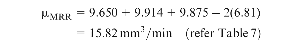
The optimum value of MRR is predicted at the selected levels of significant parameters. The significant process parameters and their optimum levels are chosen from the response graph as A3, B1 and C3, that is, pulse on time (16 µs), pulse off time (2 µs) and pulse current (6 A). The estimation mean of response characteristic (µMRR) can be computed as 13

where MRR is the overall mean of MRR (6.81 mm3/min).
The confidence interval (CI) for the predicted mean for the confirmation experiment can be calculated by the expression 13
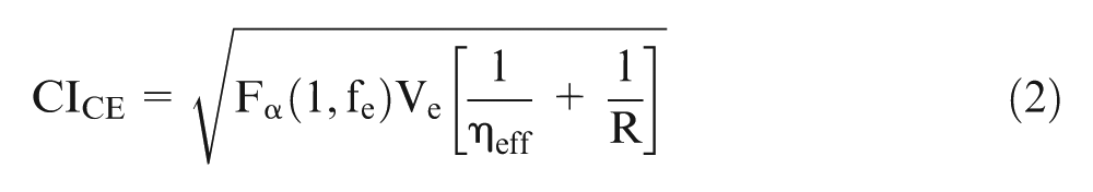
where
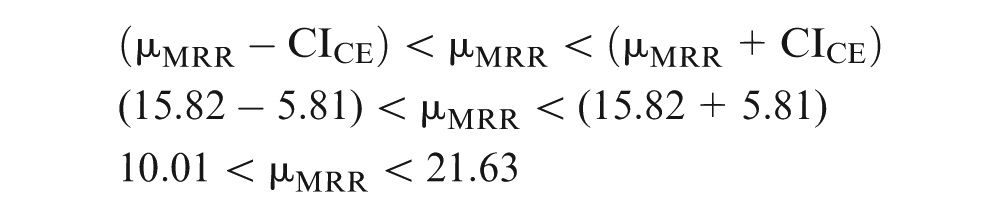
The sample size for confirmation experiment R = 1. Tabulated F ratio at 95% confidence level (α = 0.05) is F = 4.49. So CICE = ±5.81. The predicted mean of MRR is µMRR = 15.82 mm3/min. At 95% CI, the predicted optimum value of MRR is
Confirmation test
Three confirmation tests were conducted at the optimum level of process parameters. The average mean value of MRR is found and shown in Table 8.
Response at optimum levels of process parameters.
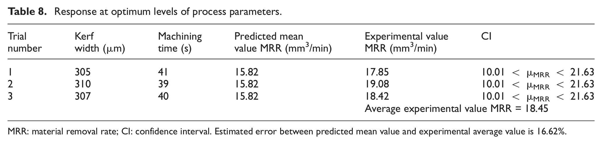
MRR: material removal rate; CI: confidence interval.
Estimated error between predicted mean value and experimental average value is 16.62%.
Microstructure and recast layer
To assess the MRR results, the SEM study of the machined surface is conducted. The SEM pictures of the machined surface of the 15 wt% (Al2O3/SiC)p/Al7075 hybrid composite are shown in Figure 9(a)–(g) at various levels of parameter settings. The surface morphology shows liquid-like formation is spread quiet evenly on the machined surface. The sequence order of SEM pictures is taken in increasing order of MRR, that is, machining time is highest at parameter setting referred for Figure 9(a) to lowest for parameter referred for Figure 9(g). The machining time is a good indicator of MRR. The lower the machining time, the higher the MRR. The most significant parameter affecting the MRR is pulse on time followed by pulse current. The different parameter settings give different machining times. In WEDM process, the molten material resulted due to discharge energy gets blasted out of the surface by discharge pressure. This blasted material leaving the surface also quickly reaches resolidification due to drastic cooling by the dielectric fluid and the substrate bulk material being at room temperature. This action produces craters and ridge-rich surfaces in the WEDM process. The resolidification of this molten material being not flushed away by the dielectric fluid forms a hard and brittle layer called white layer or recast layer. This resembles liquid-like formation on the machined surface. This white layer contains craters, globules and the black patches. Figure 9(a)–(d) is at 100× magnification and with parameter settings, giving comparatively high machining time, that is, low MRR. The least MRR is at the parameter setting of experiment 7 (refer Table 4). The MRR is low due to less spark energy at this setting. The SEM picture indicates the surface texture having very tiny localized molten metal pools, spread evenly on the surface. This is at the lowest values of pulse on time and pulse current, but highest values of pulse off time and wire drum speed. This is the lowest level of parameter setting giving highest time of machining (lowest MRR). Figure 9(b)–(d) is at little higher setting of parameter (refer Table 4). The discrete localized molten metal pools have increased in size due to intense spark energy effect owing to an increase in pulse on time and the pulse current. Figure 9(e) and (f) is at moderate setting of parameter and the SEM picture at higher magnification (300×) to indicate the effect more clearly. The localized molten metal pools are wider and deeper comparatively. The surface texture is rough due to higher melting of material and its subsequent removal from the surface. Figure 9(g) is at the highest setting of parameter showing very wide and deeper size of craters. This refers to experiment 21 (Table 4). This produces the highest value of MRR. The SEM picture is taken at higher magnification (750×). The figure clearly shows the wide and deeper size craters and the black patches. The black patches might have occurred by the arcing. This clearly indicates that more material melts and gets flushed out with an increase in pulse on time, pulse current and wire drum speed. The increase in pulse on time and pulse current generates intense dischargeenergyresulting in widening and deepening of discharge craters.
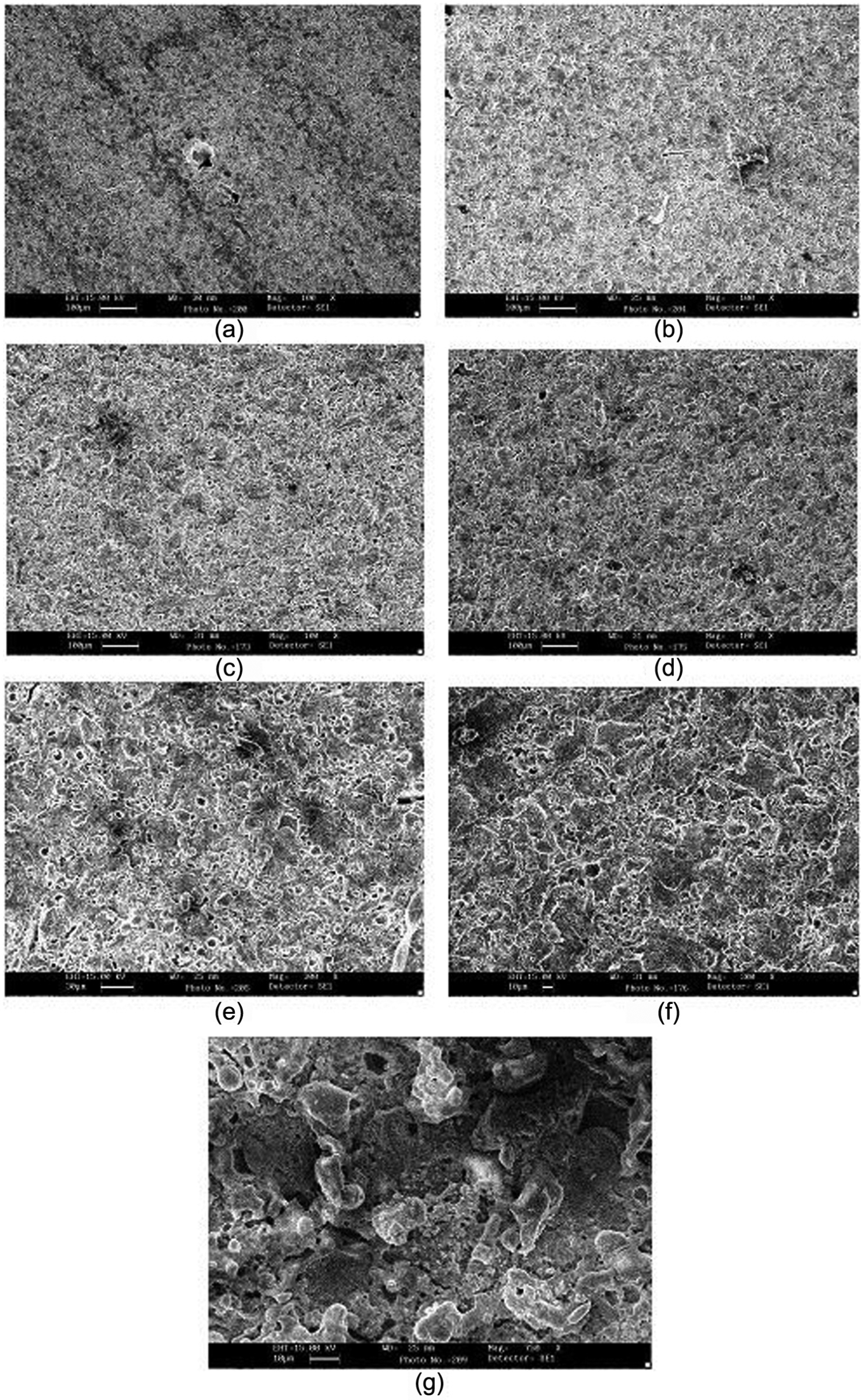
SEM pictures of the machined surface of 15 wt%/(Al2O3/SiC)p/Al7075 hybrid composite at various parameter settings: (a) Pon = 4 µs, Poff = 6 µs, Pcur = 2 A, Ws = 8 m/min; (b) Pon = 4 µs, Poff = 4 µs, Pcur = 2 A, Ws = 6 m/min; (c) Pon = 10 µs, Poff = 6 µs, Pcur = 4 A, Ws = 4 m/min; (d) Pon = 16 µs, Poff = 6 µs, Pcur = 6 A, Ws = 6 m/min; (e) Pon = 16 µs, Poff = 4 µs, Pcur = 4 A, Ws = 8 m/min; (f) Pon = 10 µ, Poff = 2 µs, Pcur = 4 A, Ws = 6 m/min and (g) Pon = 16 µs, Poff = 2 µs, Pcur = 6 A, Ws = 8 m/min.
Conclusion
Hybrid MMC of 15 wt% Al2O3 and SiC particulates (7.5% each) in Al7075 alloy was prepared using inert gas–assisted electromagnetic stir casting process. The cast hybrid composite was machined on wire EDM machine. The MRR was investigated as the response characteristic. The WEDM process parameters used in the study were pulse on time, pulse off time, pulse current and wire drum speed. The following conclusions are drawn:
The hybrid composite when processed at right parameters of melt temperature and stirring speed results in uniform distribution of reinforcement phase in the metal matrix.
The linear parameters (pulse on time, pulse off time and pulse current) and interaction (pulse on time × pulse off time) had significant effect on the MRR.
The pulse on time was the most significant parameter contributing to the MRR (46.04%), followed by pulse current (34.72%) and pulse off time (10.23%). The contribution by interaction effect (pulse on time × pulse off time) was 5.46%.
The MRR increased with an increase in pulse on time, pulse current and wire drum speed but decreased with pulse off time.
The average experimental value in confirmation test for MRR (18.45 mm3/min) is found to be within the 95% CI at optimum level of input process parameters.
The optimum value of process parameters for the predicted optimum value of MRR (15.82 mm3/min) is pulse on time (16 µs), pulse off time (2 µs) and pulse current (6 A).
The surface topography analysis shows that high level of process parameters’ setting results in large amount of metal melting in the gap, thus higher MRR.
Footnotes
Appendix 1
Declaration of conflicting interests
The authors declare that there is no conflict of interest.
Funding
This research received no specific grant from any funding agency in the public, commercial or not-for-profit sectors.