
Abstract
To reveal the engineering relationship among the electrical properties of embroidered conductive lines, the electrical properties and arrangements of conductive yarns, it is necessary to establish their equivalent resistance model. Embroidered conductive lines in textiles are usually fabricated by single-layer (conductive and nonconductive yarn used as upper and lower yarn) or double-layer embroidery technology (conductive yarns used as upper and lower yarn). Several researchers have proposed the simple resistance model for single-layer embroidered conductive line based on geometric structure of single conductive yarn in fabric. However, the double-layer conductive line has the contact resistance periodically interlaced by the upper and lower conductive yarns, and it made its equivalent circuit different from that of single-layer conductive line. In this work, a geometric model was built to describe the trace of conductive yarn in fabric, and in combination with Wheatstone Bridge theory, was applied to establish the equivalent resistance models of double-layer conductive lines with a certain width, consisted of various courses. First, the equivalent resistance model of double-layer conductive lines consisting of single course was proposed to calculate the contact resistance. Then, to obtain the electrical resistance of double-layer conductive lines with a certain width, the equivalent resistance model was extended from single course to multiple courses (
Introduction
Wearable devices are growing rapidly in communications, sports, medical monitoring, and security applications.1,2 As the essential components of many wearable electronic products, conductive lines play an important role in integrating electronics into fabrics.3,4 In general, the conductive yarns are used to form conductive line on fabric by three technologies (knitting 5 , weaving, 6 and embroidering7,8). Among these technologies, digital embroidery technology has gained tremendous attention in wearable electronics as it has the advantage of scale production and high flexibility and aesthetics and does not need glue or etching.9,10 Therefore, embroidery technology has been widely used to form textile circuits, 11 electrodes, 12 transmission lines, 13 and sensors.14,15
In the process of fabricating embroidered conductive lines, the embroidery parameters determine the distribution of conductive yarns and further affect the electrical properties of conductive lines. A number of studies show that the electrical performance of embroidered wearable electronics depends on the conductivity of conductive yarn, stitch type, and stitch spacing.16–18 Also, the result shows that stitch type has a greater influence than stitch spacing on their electrical properties. By comparing satin stitch (perpendicular to the current direction) and peripheral needle pattern (along the current direction), the conductors embroidered by the peripheral needle pattern have lower resistance.18–20 However, there is a lack of theoretical analysis on the influence of embroidery parameters on their resistance. On the other hand, Zhang proposes the resistance model of single-layer embroidered conductive line by the peripheral needle pattern according to the geometric structure of conductive yarns in the fabric. 21 The geometric structure of conductive yarns in fabric is based on the trace of single conductive yarn in fabric; however, it is not able to describe the trace consisted of upper and lower conductive yarns in fabric. Therefore, it is critical to establish a new geometric model to describe the trace consisted of upper and lower conductive yarns and further establish the equivalent resistance model of double-layer embroidered conductive lines.
Additionally, the embroidered electronics can be fabricated by single-layer or double-layer embroidery technology. For the double-layer conductive line, it has the contact resistance periodically interlaced by the upper and lower conductive yarns, which made its equivalent resistance model different from that of single-layer conductive line. This structure of double-layer conductive line indicates that its resistance model depends on the contact resistance and linear resistance of conductive yarns. Several studies have discussed on the contact resistance in wearable textiles. The contact resistance of two overlapping conductive materials for the conductive knitted fabric is inversely proportional to their contact force according to the contact resistance theory. 22 Zhang et al. 23 further establish the relationship between the normal force on the yarns and the contact resistance, and show that the contact resistance of two overlapping conductive materials can be obtained empirically. For the contact resistance interlaced by upper and lower conductive yarns, due to its contact state different from that of two overlapping conductive materials, there are currently no related reports. In Linz’s work, the conductive yarn is pierced into the hole of the conductive pad by an embroidered needle to form a loop, and contact the conductive pad to generate the contact resistance. Their contact behavior is simulated by that of conductive yarn loop tied around a cylinder and the metal conductor (acted as the conductive pad) along the height of the cylinder. 24 Then, the contact resistance can be obtained according to the measured results of the equivalent structure. Although the contact state of conductive yarn and conductive pad is different from the interlaced contact of upper and lower conductive yarns in embroidery, the method provides us an idea for the equivalent replacement method to obtain the contact resistance. As mentioned above, it is still a problem to obtain the contact resistance interlaced by upper and lower conductive yarns.
In this paper, the influence of embroidery parameters on the electrical resistance of double-layer embroidered conductive lines with a certain width, consisted of various courses, was systematically studied and the equivalent electrical resistance models were proposed. The geometric structure model of the upper and lower conductive yarns in fabric was built to describe the structure of double-layer embroidered conductive lines. On the basis of the geometric model, the contact electrical resistance interlaced by of the upper and lower conductive yarns was proposed in terms of the electrical resistance of conductive line consisted of single course, and then was applied to obtain the electrical resistance of double-layer conductive lines with a certain width, consisted of multiple courses (
Theoretical model
The establishment of embroidery stitches geometric model
The double-layer embroidered conductive line refers to the conductor formed by the upper and lower conductive yarns through embroidery technology in a certain way, as illustrated in Figure 1. In this work, the conductive yarn is assumed to be uniform and have the same electrical properties. The geometric structure of double-layer conductive lines embroidered by the peripheral needle pattern in fabric can be divided into two parts: the geometric structure of the conductive yarns on the fabric surface shown in Figure 2 and through fabric plane shown in Figure 3. Double-layer embroidery technology and embroidered conductive lines. Geometric structure of the conductive yarns on the fabric surface. Geometric structure of the conductive yarns in the thickness direction of fabric: (a) the schematic diagram; (b) the geometric model.


As shown in Figure 2, the conductive yarn embroiders along one direction to form the conductive lines with a certain length and reciprocates back and forth to form the conductive lines with a certain width, so the conductive line is composed of many stitch lengths and parallel yarns. The number of stitch length in each line can be obtained from
25
Then, the number of parallel yarns is followed as
[25]

According to equation (2), the corresponding output stitch spacing


Resistances of each part in the embroidery stitch unit model
Based on the above geometric model, single embroidery stitch unit has both length-related resistance Schematic diagram (left) and resistance model (right) of embroidery stitch unit (a) with one course; (b) with multiple courses (
Otherwise (
The establishment of resistance model of conductive line
From the resistance model of each embroidery stitch unit, the resistance models of conductive lines with various courses were established. According to Figure 4(a), there will be no contact resistance
Conductive lines with one course (
)
The model of conductive line with one course is shown in Figure 5. In the figure, the part enclosed by the red dotted line is the repeating unit along the X direction. The resistance value of the model is represented by Resistance model of double-layer embroidered conductive lines with one course (n = 1).

Conductive lines with multiple courses (
)
According to the section “Resistances of Each Part in the Embroidery Stitch Unit Model,” the contact resistance Simplified resistance model of double-layer embroidered conductive line with multiple courses (

Model validation and evaluation
Preparation of embroidered conductive lines
The silver-plated nylon multifilament yarn for embroidered conductive lines was from Qingdao Hengtong X-silver Specialty Textile Co., Ltd. (Qingdao, China). Its diameter was 0.17 mm and the linear resistance was 389 Ω/m. Cotton, 26 nonwoven fabric, 27 denim, 28 and other fabrics can be used as substrates. In this work, the nonwoven fabric was taken as examples to validate the model. Then, the conductive yarns were embroidered into a 100% polyester nonwoven substrate through a computerized embroidery machine. Polyester nonwoven was from Shandong Jiantong Engineering Technology Co., Ltd. (Dezhou, China). Its fabric thickness was 0.698 mm measured by fabric thickness gauge (YG141N, the second textile equipment Co., Ltd., Changzhou) according to the GB/T3820-1997 standard (Determination of thickness of textiles and textile products).
The double-layer embroidered conductive lines were fabricated by computerized embroidery machine (brother NV 950), as shown in Figure 1. First, the conductive lines (
In addition, to verify the resistance model of the double-layer embroidered conductive lines with multiple courses, two sets of conductive lines (
Characterization and measurement
The resistances of embroidered conductive lines were measured by a digital multimeter according to the GB/T 351-2019 standard (metallic materials-Resistance measurement method). The resistances of conductive lines in this work were measured on the rigid, nonconductive board along the direction of the stitch length as shown in Figure 7, all resistance measurements of embroidered conductive lines were repeated five times. Test diagram of conductive line.
Validation and discussion
Contact resistance caused by the interlacement of the upper and lower conductive yarns
In the section The establishment of resistance model of conductive line equations (8) and (10) show the relationship between the equivalent resistance of conductive lines with various courses and contact resistance. In order to simplify the calculation of contact resistance Contact resistance of the upper and lower conductive yarns with different stitch lengths.

Resistance of conductive lines with different stitch spacings
By inserting the resistance per unit length and related geometric parameters into equation (10), the theoretical resistances of double-layer embroidered conductive lines with different stitch spacings are obtained. Their theoretical and experimental values are shown in Figure 9. It can be seen that the simulated results were very close to the expertimental results and the trends of two data sets were generally consistent while there was a difference between the predicted results and experimental results. The difference is due to the neglect of fabric structure in the model. In fact, the fabric will be compressed under the interlacement of the upper and lower conductive yarns to reduce its thickness, which makes the simulated total length of the conductive yarns in each line larger than the actual yarn. It indicates that the simulated equivalent resistance in each line was larger than the measured values, which further made the simulated equivalent resistances larger than the experimental values according to equation (10). Additionally, it is observed that the resistances of the conductive lines increased in accordance with the increase of the stitch spacings when the stitch length was fixed. The circuit of the conductive lines is composed of many resistances (equivalent resistance in each line) in parallel, and equivalent resistance in each line is composed of many small resistances in series. In the parallel circuit, the reciprocal of the total resistance is equal to the sum of the reciprocal of each sub-resistance, and then the total resistance will be smaller if the more sub-resistances connected in parallel (Ohm’s law). The equivalent resistance of conductive lines in each line kept unchanged when the stitch length was fixed. As the stitch spacing increased, the number of parallel yarns decreased, and the number of the sub-resistances in parallel decreased and made an increase of their equivalent resistance. Simulated and experimental resistance of conductive lines with different stitch spacings.
From Figure 9, it is worth noting that the resistance of conductive line is approximately 0.35 Ω when the stitch spacing is 0.2 mm, and the resistance is approximately 2.62 Ω when the stitch spacing is 2 mm. The resistances of conductive lines increased up to around six times in accordance with the increase of the stitch spacing from 0.2 mm to 2 mm, i.e. the change of the stitch spacing makes a multiple increase of the resistance of conductive lines. Moreover, it also can be seen that the resistances of conductive lines are almost the same when their stitch spacings are 1.2 mm, 1.4 mm and 1.6 mm or 1.8 mm, and 2 mm. According to equation (2), the number of parallel yarns along the Y direction depends on the
In addition, the measured resistance of the conductive lines with different stitch spacings and its fitting curve based on the equation (10) are shown in Figure 10. The fitting equation is Measured resistance of embroidered conductive lines with different stitch spacings and its fitting curve.

Resistance of conductive lines with different stitch lengths
Similarly, by taking the resistance per unit length and related geometric parameters into equation (10), the theoretical resistance of double-layer embroidered conductive lines can be obtained. Figure 11 shows the simulated and experimental resistances of conductive lines with different stitch lengths. It can be seen that there was a difference between the simulated results and the experimental results. In the resistance model, the compression of fabric thickness probably makes the simulated total length of the conductive yarns in each line larger than the actual yarn, so that the simulated equivalent resistance in each line is larger than the measured values. In addition, the resistance of the conductive lines decreased in accordance with the increase of the stitch lengths when the stitch spacing was fixed. In the series circuit, the total resistance is equal to the sum of each sub-resistance, so the total resistance will be larger if the more sub-resistances connected in series (Ohm’s law). The number of resistances (equivalent resistance in each line) in parallel kept unchanged when the stitch spacing was fixed. As the stitch length increased, the number of stitch length in each line decreased accordingly to reduce the number of contact resistances in each line, which made the equivalent resistance in each line decrease and further resulted in the decrease of their equivalent resistance according to equation (10). Simulated and experimental resistances of conductive lines with different stitch lengths.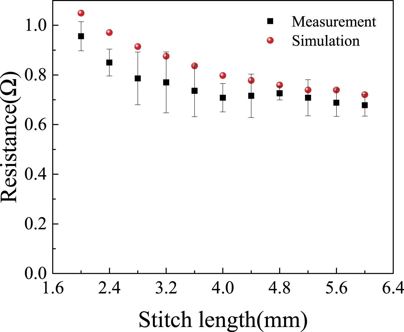
As shown in Figure 11, it is worth noting that the resistance of conductive line is approximately 0.95 Ω when the stitch length is 2 mm, and the resistance is approximately 0.68 Ω when the stitch length is 6 mm. The resistance of conductive line decreased by 28% with the increase of the stitch length from 2 mm to 6 mm; therefore, the resistance could be changed in a small range by adjusting stitch length. Moreover, it also can be seen that the resistances of conductive lines are almost the same when their stitch stitchs are 5.2 mm and 5.6 mm. According to equation (1), the number of stitch length in each line along the X diretion is determined by
In combination with the influence of stitch spacing and stitch length on the resistance of conductive line, the impact of stitch spacing on the resistance of conductive line was greater than that of the stitch length. In conclusion, when a certain resistance of conductive line was required, the stitch spacing should be determined first according to the electrical properties of conductive yarns and then adjusted the stitch length.
In addition, the measured resistances of the conductive lines with the change of stitch lengths and its fitting curve based on the equation (10) are shown in Figure 12, and the fitting equation can be divided into two parts. Measured resistances of embroidered conductive lines with different stitch lengths and its fitting curve.
For the first part, when

When

Conclusion
In this paper, the geometric structure of the upper and lower conductive yarn in fabric was built to simulate the structure of double-layer embroidered conductive lines. Based on the geometric structure, the resistance models of double-layer embroidered conductive lines with different number of courses (
Footnotes
Declaration of conflicting interests
The author(s) declared no potential conflicts of interest with respect to the research, authorship, and/or publication of this article.
Funding
The author(s) disclosed receipt of the following financial support for the research, authorship, and/or publication of this article: This research was supported by the Fundamental Research Funds for the Central Universities (2232021G-01) and the Shanghai Natural Science Foundation (20ZR1400500) and the Fundamental Research Funds for the Central Universities (CUSF-DH-D-2018033).