
Abstract
The yarn/yarn and yarn/matrix interface debonding has been recognized as a vital failure mode of 3 D braided composites. We present in this paper a meso-scale finite element (FE) model, which considers yarn/yarn and yarn/matrix interface debonding, for modeling progressive damage evolution of 3 D braided composites under typical tensile and shear loadings. In this setting, the damage state of braiding yarns and matrix is described through a continuum damage model (CDM) coupled with Murakami damage tensor; a bilinear traction-separation description is employed to govern the yarn/yarn and yarn/matrix interface behavior modeled by surface-based cohesive contact. We thus develop a user-material subroutine VUMAT (ABAQUS/Explicit) for our progressive damage simulation, including stress analysis, failure analysis and material properties degradation scheme. The mechanical properties of 3 D braided composites, and more importantly the damage evolution of interface debonding are thoroughly analyzed. The proposed FE modeling strategy provides a new perspective for the interface response study of other textile composites.
Keywords
Introduction
Three-dimensional (3 D) braided composites are a new sort of advanced lightweight composite structures, which are fabricated from fiber braided preforms impregnated and consolidated with resin matrix. The fiber yarns in 3 D braided composites form a near-net-shape integrated structure making the excellent comprehensive mechanical properties over traditional laminated composites, especially in the through-thickness direction. Nowadays, 3 D braided composites have become an important loading-bearing structural material in the aerospace engineering field, such as truss structure, beam structure, special joint structure, et al. Moreover, 3 D braided composites also are convinced to have extensive potential applications as primary structures in other high-tech industries.
Characterization of the mechanical properties of 3 D braided composites under typical loading conditions is the base for their practical engineering applications. In view of the periodic characteristics of composite structures, a unit-cell-based meso-mechanical approach is always implemented to predict the stiffness, strength and damage behavior of 3 D braided composites. Dong and Gong [1] studied the influence of random void defects in matrix on the micro-failure mechanism and tensile strength of 3 D braided composites. Fang et al. [2] and Wang et al. [3] investigated the mechanical properties of 3 D braided composites with the effects of jamming-action-induced distortion and deformation of braiding yarns. Wang et al. [4] compared the predicted elastic behavior of 3 D braided composites by three different commonly used unit-cell models and found that all the three models can provide acceptable stiffness properties results while the stress distributions are apparently affected by the cross-section shape and local curvature of the braiding yarns. Fang et al. [5], Lu et al. [6] and Ge et al. [7] conducted a progressive damage analysis to simulate the nonlinear mechanical behavior of 3 D braided composites under uniaxial tension loading. It was considered that the damage accumulation in the loading process leads to the ultimate failure of the composites. Zhang et al. [8] and Tian et al. [9] analyzed the damage evolution and failure envelopes of 3 D braided composites subjected to various uniaxial and biaxial loadings, and different strength criteria were suggested for typical braided structures. Moreover, three unit-cells models [10,11] were developed and employed for evaluating the stiffness and strength properties with the consideration of unique yarn configuration in the three different regions of 3 D braided composites. Other related works on structural modeling and mechanical properties prediction of 3 D braided composites can also be found in references [12–16].
The interface debonding among different braiding yarns and between the fiber yarns and resin matrix has been recognized as a vital failure mode of 3 D braided composites. However, in the above meso-scale FE analysis works, the interface was not involved in the established unit-cell models. With the improvement of application situations and performance requirements of 3 D braided composites, it is essential to have a complete and accurate description of the interface properties. Recently, element-based cohesive behavior, that is, cohesive elements modeling method, has been regularly used to study the interface performance and debonding mechanism of 3 D braided composites.
Lei et al. [17] developed a unit-cell model involving cohesive interface zones to analyze the cut-edge effect on the tensile damage and failure response of 3 D braided composites with different braiding angels. Fang et al. [18], Lu et al. [19] and He et al. [20] proposed a meso-scale finite element model considering the interface debonding to investigate the nonlinear mechanical behavior of 3 D braided composites under uniaxial tension. Zhang et al. [21] and Wang et al. [22] presented a meso-scale FE model, in which the interface behavior is modeled by cohesive zone model with cohesive elements, to simulate the progressive damage evolution of 3 D braided composites. Sharma et al. [23] established an image-based model to determine the elastic properties of 3 D carbon/carbon composites. Besides, Hong et al. [24] proposed a multi-scale FE method to predict the mechanical properties of 3 D braided truss joints. In this multi-scale model, the cohesive elements were introduced to simulate the yarn/matrix interfaces.
It is known that the microstructure of 3 D braided composites is very complicated and the thickness of yarn/yarn and yarn/matrix interfaces is extremely thin. Therefore, it is always a very difficult task to introduce cohesive elements in such complex microstructure by available commercial mesh software. The cohesive elements pre-compiler program is always needed to be developed and implemented to modify the computational file of the model generated from FE software, which brings a great obstacle in the model establishment and engineering application. The surface-based cohesive contact is another alternative method and it is very convenient to model the interface response between two objects where the interface thickness is negligibly small. Zhang and Zhang [25] conducted an efficient FE simulation to analyze the low-velocity impact induced delamination in laminated composites by a quasi-static loading model with surface-based cohesive contact. Jiang et al. [26,27] proposed a multi-scale FE model to investigate the tensile, shear and ballistic impact damage behavior of 2 D tri-axially braided composite. In their meso-scale model, the yarn/matrix interface debonding is descripted by cohesive surface behavior. In addition, the surface-based cohesive contact is also introduced in the microscopic damage simulation of 3 D braided composites under multiple impact compression conducted by Gao et al. [28].
The surface-based cohesive contact is naturally easier to define and allows modeling of a broader range of cohesive interactions. However, thus far, the surface-based cohesive contact has not been studied well in the meso-scale interface response simulation of 3 D braided composites due to the extremely complicated microstructure. The primary objective of this work is to investigate the interface behavior of 3 D braided composites by a robust meso-scale FE model. In this model, the yarn/yarn and yarn/matrix interfaces are introduced and modeled by surface-based cohesive contact. The damage constitutive models for braiding yarns and matrix are written with FORTRAN code and implemented by a user-material subroutine VUMAT (ABAQUS/Explicit). The mechanical behaviors of 3 D braided composites subjected to typical tensile and shear loadings are simulated and the corresponding damage mechanisms of interface are analyzed in detail. This work provides a new perspective to model and analyze the stress transfer and failure process of interface in other textile composites.
Meso-scale structural analysis
Four-step 1 × 1 braiding technique
Four-step 1 × 1 braiding technique is the commonest manner to fabricate 3 D braided composite preforms. The braiding machine is schematically displayed in Figure 1. The motion process of yarn carriers on the machine bed in a braiding cycle is briefly described in Figure 2. Each braiding cycle contains four motion steps and each carrier moves one position at one step horizontally or vertically in an alternating routine. After the four-steps, all the carriers return to their initial configuration with different locations. Then a jamming action is imposed on all the yarns, which causes the yarn structure to be steadied and compacted. Accordingly, a braiding pitch length of preform, denoted by h, is fabricated. The continuous repetition of the above four-step motion and jamming action gradually form the required preforms.
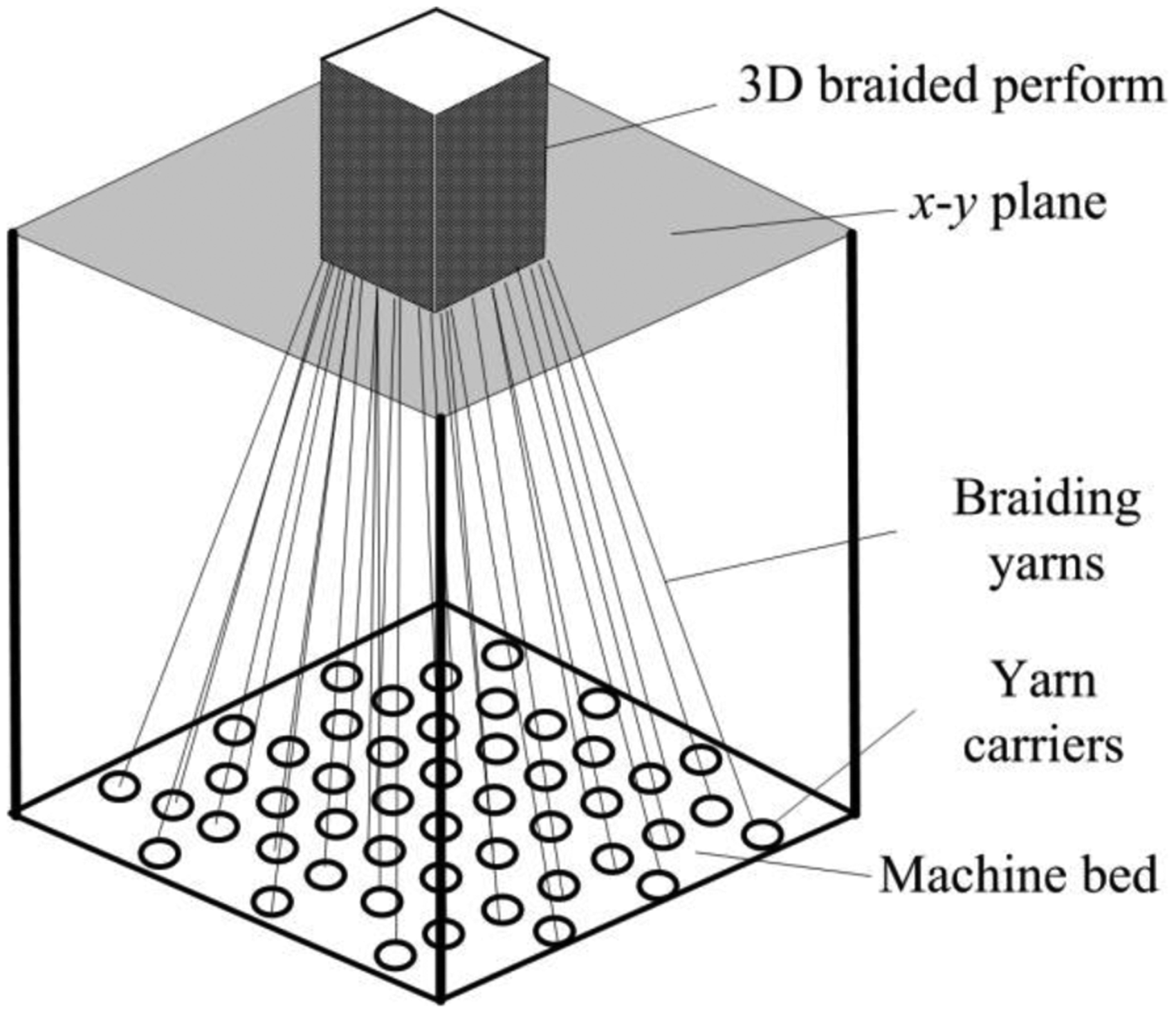
Schematic diagram of four-step 1 × 1 braiding machine.

Four-step motion process of yarn carriers on the machine bed.
Analysis of yarn paths in the interior region
According to the braiding process, it is clear that the motion of carriers in the interior, surface and corner regions is different, which results in unique yarn configuration in these three regions. However, up to now, the problem of how to apply the reasonable boundary conditions when the interior, surface and corner unit-cells are considered simultaneously has not been really solved. In this work, only the yarn configuration in the interior region of preform is analyzed for the realistic establishment of interior unit-cell model. As presented in Figure 3(a), for a typical carrier 22 in the interior region, it follows a zig-zag trace on the machine bed during a four-step braiding cycle and the position points are A, B, C, D and E respectively. The corresponding spatial trace of carrier 22 from position point A to E is displayed in Figure 3(b). The position point of the yarn carrier is also recognized as the control point of yarn motion path but this control is temporary. Subsequently, due to the effect of yarn tension in the jamming action, the yarn will be straightened and repositioned, as described by segment A’E’ in Figure 3(a) and (b). The yarn paths in the interior region are all placed in two groups of orthogonal planes and projected in the x-y plane with orientation angle ±45°, as illustrated in Figure 3(c). Herein, a representative volume element, i.e., the interior unit-cell, is selected by a square box, and the geometrical model of the interior unit-cell is provided in Figure 3(d).

Yarn configuration in the interior region of preform (a) Planar motion trace (b) Spatial motion trace (c) x−y plane projection of yarn trace (d) Geometrical model of interior unit-cell.
Structural model of interior unit-cell
Due to the good periodicity in textile composites, the meso-scale FE modeling approach is generally employed to study the mechanical properties of composites by establishing a unit-cell model. For 3 D braided composites, it is extremely difficult to include all the unit-cells in the interior, surface and corner regions simultaneously, especially for the damage analysis problems. In practice, only the interior unit-cell, the main-part of 3 D braided composites, is employed in this meso-scale FE modeling. That is, 3 D braided composites are assumed as periodic structure consisting of periodic arrangement of interior unit-cells.
Chen et al. [29] observed that the yarn axes remain straight and the braiding yarns keep surface contact under mutual squeeze, as exhibited in Figure 4(a). In view of such structural characteristics of braided preform, a unit-cell model with straight and octagonal cross-section braiding yarns [30] is adopted in this paper. As depicted in Figure 4(b), the cross-section of the braiding yarns is octagon taking an inscribed ellipse. The relationship between the major and minor radii, a and b, of the ellipse and the interior braiding angle γ, is formulated as

Meso-scale structure of 3 D braided composites (a) SEM micrograph (b) Structural model of interior unit-cell [29].
According to the spatial configuration and geometrical relationships in the unit-cell model, the related structural parameters can be determined as below


In equations (1) to (3), W, T and h are the width, thickness and height of the unit-cell model, respectively; Sb is the cross-sectional area of braiding yarn.
The fiber volume fraction Vf of 3 D braided composites can be computed by

Generally, the braiding angle α can be measured conveniently on the surface of composites and it has a simple relation with the interior braiding angle γ, namely

Progressive damage model
Based on the unit-cell model, the progressive damage simulation mainly contains stress analysis, failure analysis and material properties degradation scheme. Stress analysis involves proper constitutive relationships of each constituent; failure analysis employs appropriate damage initiation criteria to describe the possible failure modes; material properties degradation scheme reduces the material properties based on the proposed damage evolution model.
Progressive damage model of braiding yarns and matrix
Murakami damage tensor [31] is employed here to represent the damage state of braiding yarn and resin matrix, namely

Allowing for the symmetry, the effective stress of damaged material is expressed as

By energy identification, the damage tensor is introduced into the stiffness matrix of damaged material as

The expression of equation (8) can be given more explicitly by the original elastic constants and the principal values of damage tensor, namely [32]
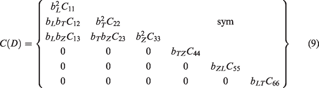
In the above equation,
For braiding yarns, the three principal damage variables can be determined by


In equations (10) to (12),
For resin matrix, one has

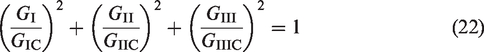
In this simulation, 3 D Hashin failure criteria [33] and Maximum Stress Criteria are adopted as the damage initiation criteria of braiding yarn and resin matrix. In these criteria, four typical failure modes of braiding yarn and tensile and compressive failure of resin matrix are defined. Once the damage initiation criterion is reached, the evolution of damage variable for each specific damage mode is determined by [5]

Here,


In the above equations,


The above progressive damage models of braiding yarn and matrix are coded by a user-material subroutine VUMAT and carried out in ABAQUS/Explicit solver.
Progressive damage model of interface
Interface debonding is known as a representative and vital failure mode in textile composites. Generally, two methods, cohesive elements and surface-based cohesive contact, are employed for modeling the interface issues. According to specific problems, the mechanical constitutive response of the cohesive layer with cohesive elements can be defined with a continuum-based constitutive model or by using a traction-separation description. However, the introduction and mesh generation of interface in complex meso-scale model is extremely difficult. On the other hand, cohesive contact is a convenient and simplified manner, especially in complex meso-scale model, to simulate the cohesive connections using contact interactions and traction-separation interface behavior.
In this work, surface-based cohesive contact is adopted to simulate the yarn/yarn and yarn/matrix interface of 3 D braided composites. The interface behavior is governed by a mix-mode bilinear traction-separation law, which assumes initially linear elastic response followed by the linear evolution of damage, as displayed in Figure 5.

Mix-mode bilinear traction-separation law of interface [34].
The initial elastic response of the interface can be represented as

For 3 D braided composites, it is known that the initiation and evolution of interface debonding is determined by the combination of failure modes I, II and III. To involve the combination of normal and shear separations, the effective relative displacement, δm, is introduced as

The initiation displacement of interface debonding,

The complete failure displacement of interface debonding,
After damage initiation, the damage evolution of interface is defined by

Here, considering the irreversibility of interface debonding, the maximum relative displacement during the loading process,
Therefore, the bilinear traction-separation law of interface under mixed-mode condition is descripted by equation (24).


When the interface behavior is introduced and modeled, the convergence of computation will be deteriorated seriously in the static implicit analysis. To avoid the termination of computation, an applicable and effective ABAQUS/Explicit based quasi-static analysis is implemented here. The load is applied dynamically by smooth loading mode and the load time is set as 0.001 s, which can ensure the ‘real’ quasi-static of the solution.
Meso-scale finite element modeling
Periodic boundary conditions
The meso-scale FE modeling is based on the periodic unit-cell model, so the periodic boundary conditions proposed by Xia et al. [35] are implemented here to reflect the repeatability features. For the unit-cell model, the displacements on a pair of parallel opposite boundary surfaces can be expressed by


Herein, given that

Equation (27) is imposed in the meso-scale FE modeling by setting nodal displacement constraint equations based on ABAQUS/Explicit. The detailed and explicit application practice can be found in Ref. [36].
Mesh discretization
Periodic mesh at paired parallel surfaces of the unit-cell model should be guaranteed in order to impose the periodic boundary conditions on the corresponding paired nodes. Four-node tetrahedral element (C3D4) is used to discretize the braiding yarns and matrix due to its outstanding geometry adaptability, as illustrated in Figure 6. Here, the convergence of mesh solution can be satisfied since the mesh sensitivity analysis had been achieved. That is, the FE mesh used in this work is fine enough to reach the convergence results. Zero-thickness interface is assumed and surface-based cohesive contact is defined directly by the surface interaction properties between yarn/yarn and yarn/matrix interfaces in 3 D braided composites as “General contact” in ABAQUS/Explicit solver. That is, interface mesh is not required when using the surface-based cohesive contact. Besides, it should be pointed out that debonding damage in surface-based cohesive contact is an interaction property, not a material property.

Mesh discretization of unit-cell model.
Unit-cell homogenization
To identify the macroscopic mechanical properties of 3 D braided composites, the unit-cell homogenization approach is adopted. The average stress and strain in a unit-cell are defined by


The relation of average stress and strain is given by

In this simulation, the average strain

Numerical results and analysis
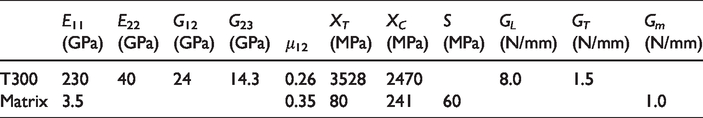
In this section, the process parameters of two specimens with typical braiding angles [37] and corresponding structural parameters of unit-cell models, given in Table 1, are implemented to conduct the meso-scale FE modeling. The material properties of Toray T300 fiber and Jindong TDE-86 resin matrix are summarized in Table 2 and the proper properties of cohesive interface cited from Ref. [21] are provided in Table 3. The stiffness and strength of impregnated yarn consisting of thousands of fibers are obtained by the rule of mixture proposed by Chamis [38]. Local coordinates L-T-Z are assigned to the braiding yarns in the unit-cell, where L, T and Z axes represent the longitudinal and two transverse directions. Owing to the special spatial configuration of braiding yarns, the mechanical behavior of unit-cell in x and y directions are similar. Therefore, only the typical tension and shear loading cases: z tension, x tension, xy shear and xz shear, are employed in the following numerical simulation.
Process parameters of the specimens and corresponding structural parameters of the unit-cells.

Material properties of carbon fiber and resin matrix.
Properties of cohesive interface.

Elastic response of unit-cell model
By meso-scale FE modeling, the detailed information on the elastic response of unit-cell model under different loading conditions can be achieved, which is the premise to effectively simulate the damage evolution in 3 D braided composites. The stress distributions on unit-cell models with deformed shape of the two specimens under typical loadings are illustrated in Figure 7. In all the loading cases, the average strain of unit-cell is set as 0.2% while the deformation scale factors are set as 20 and 50 for specimen 4DS1 and 4DS2. From Figure 7, it can be seen that the deformations of unit-cells properly reflects the corresponding applied loading states and the paired parallel surfaces no longer remain plane but warped. Especially, under z tension, the warping is most noticeable on the top and bottom surfaces while it is not significant on the other two paired boundaries; under xy shear, the warping is obvious on the two side paired surfaces while it is not apparent on the top and bottom boundaries. Certainly, the warping of the three pairs of parallel surfaces is always different in distinct loading cases. This is due to the asymmetry of geometrical structure and anisotropy of physical properties in 3 D braided composites. However, the deformations on each paired opposite surfaces are always identical and the displacement difference keeps constant, which guarantees the displacement continuity condition of unit-cell-based FE modeling.

Stress distributions on unit-cell models with deformed shape of specimens under typical loadings (a) Specimen 4DS1 (b) Specimen 4DS2.
Besides, it can also be observed from Figure 7 that the stress distributions are extremely similar on the paired opposite surfaces of unit-cell under all these loading conditions. That is, the traction continuity condition of meso-scale FE modeling can also be satisfied and appropriate stress distributions are obtained in this simulation. Under various loading conditions, the average stress level in the yarns is always significantly greater than that in the matrix. It is attributable to that the load sharing of yarns and matrix in the unit-cell is determined by their stiffness properties and the stiffness of yarn is much higher than that of matrix. The load-bearing status of yarns and matrix varies under every loading case, which results in different mechanical response of the unit-cell. However, because of the spatial distribution of yarns in the unit-cell, the braiding yarns in different directions can participate in the load-bearing coordinately under these loadings. Moreover, the stress concentration is invariably inclined to occur in the yarn/yarn and yarn/matrix contact regions of unit-cell, which indicates that the interface debonding may be the easiest and earliest damage mode in the damage evolution process of 3 D braided composites.
Stress-strain curves
The stress-strain curves attained by unit-cell homogenization express the macro-mechanical properties of 3 D braided composites. Figure 8 represents the simulated stress-strain curves of the two specimens under typical loading conditions and the available experimental stress-strain curves in z tension cases are selected here for comparison. In fact, the carbon-fiber reinforced 3 D braided composites generally show brittle fracture in physical test and the stress-strain curve stops immediately once reaching the maximum stress. In contrary, the simulated stress-strain curves reflect the virtual progressive damage evolution of composites. After reaching the maximum stress, the simulated curve decreases suddenly or gradually according to the specific loading case thus leads to the corresponding decrease of load-bearing capacity of composites.

Stress-strain curves of specimens under different loading cases (a) Specimen 4DS1 (b) Specimen 4DS2.
Under z tension loading, for specimen 4DS1 with a small braiding angle, the simulated stress-strain curve shows a good linear relation before reaching the ultimate strength of the specimen, which agrees well with the experimental phenomenon. The abrupt expansion of critical damage mode leads to the sudden brittle breaking failure of material. On the other hand, for specimen 4DS2 with a large braiding angle, the simulated stress-strain curve exhibits certain nonlinear relation before reaching the maximum stress and then decreases gradually. This nonlinear phenomenon is caused by the local damage initiation and propagation in the loading history and the progressive damage accumulation in this process results in the final failure of composites. It can be found that the predicted ultimate strengths and failure strains in z direction are always higher than the experiment results, especially for specimen 4DS2. This can be attributed to the following factors. First, the possible geometrical and manufacturing defects are not introduced in the proposed unit-cell model. Second, the failure of specimen 4DS1 is controlled by yarn L tensile failure while that of specimen 4DS2 is governed by matrix cracking and interface debonding, and then the in-suit properties of matrix and interface adopted here might not be accurate. Furthermore, the present meso-scale modeling is only based on the interior unit-cell while the surface and corner unit-cells are ignored, however the actual damage of 3 D braided composites may initiate at the surface region.
For specimen 4DS1, the simulated stress-strain curves exhibit relatively good linear response in the loading process of xy and xz shear. For specimen 4DS2, the linear response is only observed in the loading history of xz shear while a turning point appears in the xy shear loading process. For both specimens 4DS1 and 4DS2, under x tension, the stress-strain curves present obvious nonlinear characteristics before reaching the maximum stresses. The extended unloading stages provided in the simulated stress-strain curves of specimen under different loading cases are regarded as a computational effect, which can improve the convergence of computation and also can continue to provide the damage evolution of material. Moreover, for specimen 4DS1, in x tension, xy shear and xz shear cases, the interface debonding appears first, followed by the yarn damage, and the matrix damage appears at last. In contrast, the yarn damage appears lastly in z tension case. For specimen 4DS2, the interface debonding initiates first and the yarn damage happens subsequently whereas it is different in x tension case. However, the matrix cracking always takes place at last.
It can also be found that the shear strengths of 4DS2 are higher than the tensile strengths. This is because that for the specimen with a large braiding angle, both the yarn and interface bear the loads under tensile load while just the yarn bears the main loads under shear load. Accordingly, the interface damage has great influence on the load-bearing performance under tensile load while it is not very significant under shear load.
Damage evolution analysis
By unit-cell-based FE modeling, in addition to the deformation and stress distribution, the detailed information on damage evolution in the loading process can also be attained. The main damage modes and failure mechanisms of specimens with typical braiding angles under distinct loading cases are generally different. In this simulation, more attention is concentrated on the damage evolution of interface debonding, as illustrated in Figures 9 and 10.

Damage evolution of interface debonding in specimen 4DS1 under typical loadings.

Damage evolution of interface debonding in specimen 4DS2 under typical loadings.
For specimen 4DS1, in z tension case, the main failure modes are yarn L tensile failure, matrix cracking and interface debonding. As represented in Figure 9(a), the interface debonding initiates at
For specimen 4DS2, in z tension case, the main failure modes are yarn T compressive shear failure, yarn Z tensile shear failure, matrix cracking and interface debonding. As shown in Figure 10(a), the interface debonding initiates when
Conclusions
The interface is an intrinsic constituent in 3 D braided composites with a significant influence on the damage evolution process of composites. In this paper, a meso-scale FE model, with the interface modeled by surface-based cohesive contact, is developed to study the damage behavior of 3 D braided composites. The FE model is verified with available experimental results in z tension condition and then applied to predict the mechanical behavior in shear cases. The progressive damage simulation is carried out based on ABAQUS/Explicit solver and the proposed damage constitutive models are implemented through a user-material subroutine VUMAT. The elastic deformation and stress distribution, stress-strain curves, damage modes especially interface debonding, are predicted and analyzed in detail. We recognize that the stress transfer and cohesive failure process of interface in 3 D braided composites are significantly different under distinctive loadings. Relatively balanced load-bearing of braiding yarn can be gained under tension loadings because of the spatial symmetry of yarn in the unit-cell. Both the normal and shear stress components contribute to the damage evolution of interface under tension loadings. Under shear loadings, the interface debonding in the internal yarn/yarn contact regions of unit-cell is not balanced caused by the yarn directional effect in load-bearing and the shear stress components make a great contribution to the damage evolution of interface.
Since the surface-based cohesive contact is an effective and convenient method to simulate the interface response of 3 D braided composites and the proposed meso-scale FE model and modeling strategy is general and robust, it actually provides a transferable approach to study the interface problems in other textile composites.
Footnotes
Declaration of conflicting interests
The author(s) declared no potential conflicts of interest with respect to the research, authorship, and/or publication of this article.
Funding
The author(s) disclosed receipt of the following financial support for the research, authorship, and/or publication of this article: This work was supported by the National Natural Science Foundation of China (11832014), Natural Science Foundation of Jiangsu Province (BK20180855) and Research Fund of State Key Laboratory of Mechanics and Control of Mechanical Structures (Nanjing University of Aeronautics and astronautics) (MCMS-E-0219Y01).