
Abstract
Fatigue is an important factor leading to the structural failure of 3D braided composites during the service. In this paper, a meso-scale finite element analysis (FEA) model based on continuum damage mechanics (CDM) is developed to study the fatigue damage behavior and predict the fatigue life of 3D braided composites subjected to off-axial tension loadings. Stress analysis, failure criteria and material properties degradation scheme in the meso-scale model are implemented by a user-material subroutine UMAT based on ABAQUS/Standard solver. The damage initiation and propagation of 3D braided composites under diverse off-axial fatigue loadings are simulated and analyzed in detail and the corresponding off-axial fatigue lives are obtained from the predicted S-N curves. The proposed FE modeling provides a suitable reference for the numerical research on the off-axial fatigue problems in other textile composites.
Introduction
3D braided composites have been increasingly applied in the aerospace, automotive and other high-tech industries in the past two decades because of their excellent comprehensive mechanical properties. As the primary load-bearing structures, 3D braided composites in service are usually subjected to severe alternating cyclic loadings, which could eventually result in fatal fatigue failure in the composite structures. Due to the lack of effective fatigue prediction model and damage analysis approach, lots of experiments are needed in the design stage and a larger safety factor is adopted to cover the fatigue risk. Under such circumstances, the advantage of high weight-reduction efficiency of 3D braided composites cannot be fully realized in practical application. Therefore, it is of great significance to establish a robust numerical analysis model within the FE frame to predict the fatigue performance and damage behavior of 3D braided composites.
Progressive fatigue damage model (PFDM) proposed by Shokrieh and Lessard1,2 is a common FE frame and independent of the specific composite structures. It is capable of predicting the residual stiffness, residual strength and fatigue life and simulating the damage evolution thus has significant advantages and broad potential applications. For textile composites, it mainly involves the meso-scale model, constitutive relation of constituents, fatigue failure criteria and material properties degradation scheme. Currently, PFDM have been adopted and further developed by many researchers to predict the fatigue life and damage evolution of different textile composites under on-axial loading conditions. Xu et al.3,4 proposed a unit-cell based FE model to predict the damage initiation and evolution of 2D textile composites in tension-tension fatigue loading. The algorithm of multi-axial fatigue was applied to matrix-dominated fatigue while the fiber-dominated fatigue was separately considered. Zhang et al. 5 and Hao et al. 6 developed a meso-scale FE model to simulate the damage evolution process of 3D braided composites under fatigue tension loadings. The fatigue damage accumulation during cyclic loading was involved in the developed model for predicting the fatigue life more accurately. Guo et al. 7 adopted FPDM to assess the fatigue failure behavior of 3D woven composites, in which the damage irreversibility and compressive crack closure effect were considered. Fiber bundle unit-cell model and braided unit-cell model were established by Wang et al. 8 to predict the fatigue life of 2D braided composites including diverse damage modes. However, due to the difficulty of determining various damage variables, the implementation of the proposed model was relatively challenging. Other similar FE models for investigating the fatigue life and damage evolution of typical textile composites can be found in Refs.9–14
The above works concentrated on the on-axial tension and compression fatigue behaviors of textile composites while the study on off-axial fatigue performance has not been reported up to now. Actually, off-axial loading is a most general scene of loading condition in service. The researchers mainly conducted experimental and numerical studies to analyze the static behaviors of textile composites under off-axial loadings. Cai et al. 14 experimentally studied the off-axial mechanical properties of unidirectional and woven composites. It was indicated that the woven composites present apparent nonlinear stress-strain behaviors under off-axial tension loadings. Zhou et al. 15 and Wang et al. 16 analyzed the off-axial progressive damage behaviors of woven composites based on unit-cell simulation. Besides, Zhang et al.17,18 presented a meso-scale FE model to discuss the void defects and interface properties on the off-axial tension behavior of 3D braided composites. These off-axial statics analysis works have confirmed that the off-axial behavior of textile composites have significant difference compared with those under on-axial loadings. The off-axial load-bearing capacity cannot be directly characterized by on-axial loading tests and the damage modes and failure mechanism are much more complicated. Consequently, for the safe application under fatigue situation, it is very necessary to further study the effect of off-axial fatigue loading on the mechanical properties, damage evolution and fatigue life of textile composites.
Establishing the meso-scale fatigue damage model, predicting the fatigue life and analyzing the failure mechanism are the basis for improving the performance potential and application level of composite structures. In this paper, a meso-scale FE model based on PFDM frame is developed to study the damage evolution and fatigue life of 3D braided composites under various off-axial fatigue tension loadings. The obtained numerical results show that the proposed modeling strategy can provide an effective approach for investigating the similar off-axial fatigue issues in other textile composites.
Progressive fatigue damage model
PFDM consists of three major parts: stress analysis, fatigue failure criteria and material properties degradation scheme. In the present unit-cell model of 3D braided composites, the resin matrix is regarded as isotropic material; braiding yarn is considered as transversely isotropic unidirectional composites in the local L-T-Z coordinate where L, T and Z axes designate the longitudinal and two transverse directions.
Fatigue failure criteria
3D Hashin failure criteria 19 and maximum stress criteria are adopted as the fatigue failure criteria of braiding yarns and resin matrix, respectively.
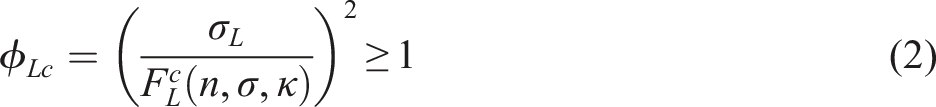
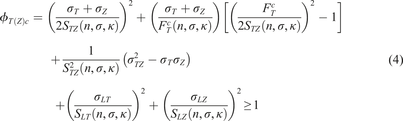
For braiding yarns, the expressions of 3D Hashin failure criteria can be given as follows:
Yarn tensile fatigue failure in L direction (

Yarn compressive fatigue failure in L direction (
Yarn tensile and shear fatigue failure in T and Z direction (

Yarn compressive and shear fatigue failure in T and Z direction (
In the above equations,
The tensile and compressive fatigue failure of matrix are defined by maximum stress criteria, namely


Damage constitutive model of constituents
The damage state of braiding yarn and matrix can be described by Murakami damage model,
20
namely


Here,
For braiding yarn, the three principal damage variables are determined by


For matrix, the damage variables are determined by

Material properties degradation scheme
For fatigue modeling, two material properties degradation schemes are considered: linear progressive reduction and gradual properties degradation. Once the fatigue failure criterion of certain mode is satisfied, the linear progressive reduction will be performed. Moreover, the gradual properties degradation is always implemented during the whole fatigue cycles until fatal failure.
Linear progressive reduction
Linear progressive reduction is employed for each damage mode, namely
22


Here l is the characteristic length of element; < > symbolizes the Macaulay operator.
Gradual properties degradation
Under fatigue loading, the strength and stiffness of material degrade gradually and eventually leading to the attainment of fatigue failure criteria. It should be pointed out that since the mechanical properties of 3D braided composites are mainly determined by braiding yarns and the necessary fatigue data of matrix are not available, the gradual properties degradation is not applied for pure resin matrix in this simulation.
In this work, the residual strength and stiffness models for unidirectional composite are used for braiding yarn. However, this simplified assumption may introduce some computational errors in the simulation model, for example, the twisting and bending state of braiding yarn cannot be well considered here.
The residual strength


In the above equations,
In order to make the gradual properties degradation appropriate to any stress ratio and stress state, the normalized fatigue life model is applied.
Under longitudinal and transverse fatigue loadings, one has
23

Under shear fatigue loading, one has
23

In the above equations,
Finite element modeling strategy
Meso-scale FE model
As shown in Figure 1(a) meso-scale unit-cell model of 3D braided composites developed by Xu et al.
24
is adopted to simulate the fatigue damage behavior. The cross-section shape of braiding yarns is assumed as octagon containing an inscribed ellipse. The relationship between the major and minor radii of ellipse, a and b is determined by Meso-scale FE model of 3D braided composites (a) Unit-cell structural model (b) FE mesh.


According to the geometry relation, we have


In the above equations, W, T, h, V are the width, thickness, height and volume of the unit-cell models, respectively;
In order to facilitate the application of periodic boundary conditions, periodic meshing of unit-cell is necessary. Because of the complicated microstructure of 3D braided composites, it is a challenging task to generate periodic mesh. 3D solid tetrahedral element (C3D4) is selected to discretize the unit-cell model due to the excellent geometry adaptability and the surface mesh mapping method is adopted in the meshing process to facilitate the formation of periodic mesh, as displayed in Figure 1(b). Herein, the co-nodes mesh is adopted in the yarn/yarn and yarn/matrix interfaces.
Material properties of carbon fiber and resin matrix. 17

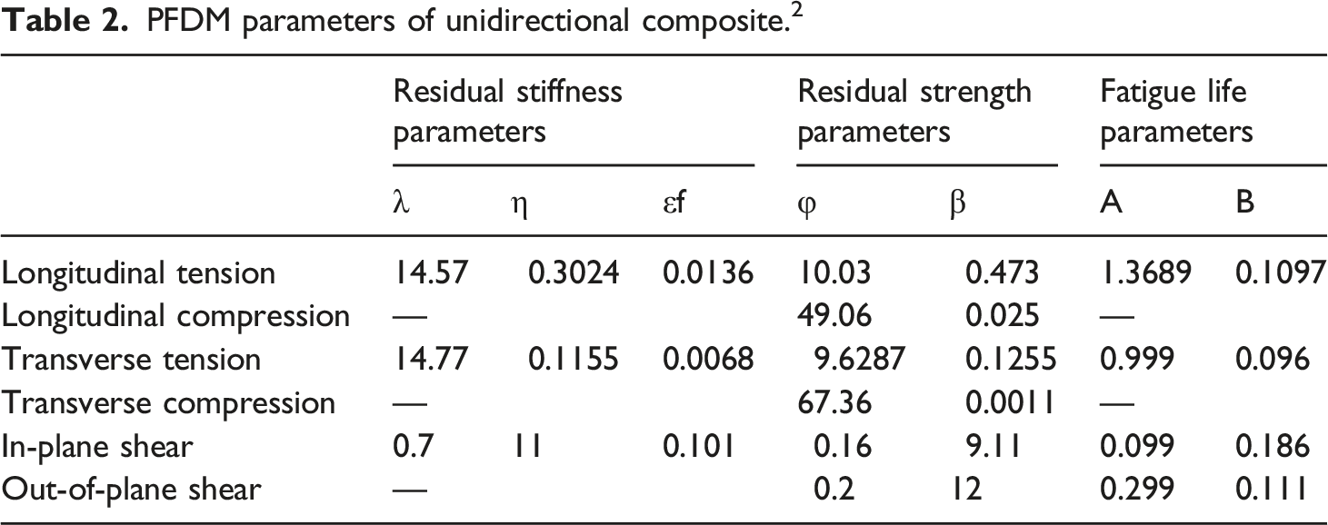
PFDM parameters of unidirectional composite. 2
Both the force and displacement modes can be acted as applied load to employ the periodic boundary conditions. In this work, to achieve accurate loading level in the simulation, the force loading mode is adopted in both the static strength prediction and fatigue damage analysis. Nodal displacement constraint equations of related surfaces, edges and corners are established to implement the periodic boundary conditions on the unit-cell model. And the process that how to apply the periodic boundary conditions to unit-cell model can be found in our previous work. 25
The macroscopic mechanical properties of 3D braided composites are obtained by unit-cell homogenization.
The average stresses 
Implementation of fatigue failure modeling
Basic assumptions
Two main assumptions 26 have been made to simulate the fatigue loading in the meso-scale FE model for improving the computational efficiency and saving the computer resource. (a) During each loading cycle, damage development in the unit-cell only happens at maximum and minimum fatigue stresses. (b) For the chosen cycle jumps, only gradual degradation of the material properties is involved.
According to the first assumption, only the maximum fatigue loading is needed to be applied with stress ratio R=0.1. The second assumption is made to contain the gradual properties degradation in a specific cycle jump and then perform a new failure analysis. In this work, the fatigue analysis is evaluated at cycles
Fatigue failure analysis process
User-defined material subroutine UMAT in ABAQUS/Standard is adopted to conduct the progressive fatigue damage simulation. Static strength prediction and fatigue failure analysis are the two computational modules in the meso-scale modeling. The flow chart of the whole simulation is illustrated in Figure 2. Flow chart of progressive damage analysis process (a) Static strength prediction (b) Fatigue failure analysis.
As shown in Figure 2(a), in each load increment, the stress analysis and failure analysis are performed at Gauss integration points of the elements. Once the failure criterion is satisfied, the linear progressive reduction is executed by updating the damage variable of specific damage mode. The stress analysis needs to be performed repeatedly before the final static failure. The static analysis is finished when the eventual failure happens and the static strength can be obtained from the predicted stress-strain curve.
As displayed in Figure 2(b), the stress analysis is performed based on the maximum fatigue stress level. If an element reaches the failure criteria, the linear progressive reduction considering specific damage mode will be conducted. Once the final fatigue failure criterion is satisfied, the current number of cycles is assumed as the fatigue life of 3D braided composites and the fatigue analysis stops. If there is no fatigue failure in the element, it is necessary to determine whether the fatigue limit is reached. If the number of cycles is smaller than the fatigue limit, the gradual properties degradation of yarn element is implemented and the selected cycle jump is applied to perform a new analysis again. If the fatigue limit is reached before the final fatigue failure, the fatigue life at the present stress level is defined as the fatigue limit and the fatigue analysis ends.
Final failure criterion
An appropriate final criterion which determines the ultimate failure of the unit-cell model is needed in the simulation. Under either static or fatigue loading condition, the fatal failure happens when 3D braided composites cannot bear further loading because of extensive damage. In the static analysis, the static strength is defined as the inflection point of the predicted stress-strain curve. On the other hand, in the fatigue analysis, it is considered that the final fatigue failure occurs when the composite structure can no longer bear the fixed force loading or the finite element computation cannot be convergent.
Off-axial loading and stress state analysis
As demonstrated in Figure 3(a), the unidirectional composite is subjected to off-axial tension loading. Here, the off-axis and on-axis coordinate systems can be regarded as global and local coordinates and represented by 1–2 and X-Y, respectively. As presented in Figure 3(b), the off-axial loading is only applied to the unit-cell model of 3D braided composite in the XY plane. Since only the plane stress transformation is involved, the on-axial multidirectional stress can be transformed from the off-axial unidirectional stress through stress transformation matrix, which can be expressed as Unidirectional laminate under uniaxial off-axial tension loading.

Then, the stress in the global coordinate system can be converted to the stress in the local coordinate system by
Numerical results and discussion
Process parameters of the specimens and corresponding structural parameters of the unit-cells.

Prediction of static strength
For the convenience of description, the on-axial loading is considered as a special off-axial loading with off-axis angle 0°. The stress-strain curves of the unit-cell models of two specimens under different off-axial static tension loadings are provided in Figure 4. Our previous work
27
has demonstrated that the stress at the inflection point of the predicted stress-strain curve under force loading mode can be regarded as the static strength of specimen. For the two specimens with different braiding angles, the variation law of off-axial tensile strength with the increase of off-axis angle is completely different. For specimen 4DS1, the off-axial tensile strength decreases gradually when the off-axis angle increases from 0° to 45°. In 0° case, the tensile strength of specimen 4DS1 is 435.86 MPa, which is about 4.58 times of that in 45° case. For specimen 4DS2, when the off-axis angle increases from 0° to 30°, the off-axis tensile strength increases gradually. And then, when it continuously increases to 45°, the off-axial tensile strength decreases slightly. In 30° case, the off-axial tensile strength of specimen 4DS2 is 160.00 MPa, which is about 1.38 times of that in 0° case. The different variation laws of off-axial tensile strength of the two specimens indicate that the braiding angle has great influence on the static properties of 3D braided composites. The specific off-axial tensile strengths of the two specimens are summarized in Table 4. Stress-strain curves of 3D braided composites under off-axial static tension loadings (a) Specimen 4DS1 (b) Specimen 4DS2. Off-axial tension strengths of specimen 4DS1 and 4DS2.

For specimen 4DS1, the failure mode changes significantly with the increase of off-axis angle. Under 0° and 15° off-axial static loadings, the main failure mode of braiding yarn is L tensile failure. However, the damage extent of yarn L tensile failure under 15° loading is significantly smaller than that under 0° loading, but the yarn transverse tensile shear and compressive shear failure modes emerge obviously in 15° case. The main failure mode of braiding yarn in 30° and 45° cases is transverse tensile shear failure, which is mainly distributed on the surface of yarns with a larger inclination angle between the fiber direction and off-axial loading direction. Figure 5(a) illustrates the distribution of yarn Z tensile shear failure of specimen 4DS1 under 30° static tension. Under all the off-axial static loading states from 0° to 45°, matrix cracking is one of the main damage modes at ultimate failure and concentrates in the yarn/matrix contact zone. Damage distribution of yarn Z tensile shear failure under off-axial static tension loadings (a) Specimen 4DS1 in 30° case (b) Specimen 4DS2 in 45° case.
Much yarn L tensile failure occurs in specimen 4DS2 under 0° static loading but only a small amount of yarn T compressive shear failure and Z tensile shear failure can be observed in the yarn/yarn contact zone. During the increase of off-axis angle from 15° to 45°, the quantity of yarn L tensile failure decreases gradually while yarn T compressive shear failure and Z tensile shear failure expand gradually from the yarn/yarn contact zone to the whole yarn along the fiber direction. Yarn L tensile failure is limited in 45° case and the main damage mode is the yarn transverse tensile failure, which mainly occurs in the braiding yarns with a larger inclination angle between the fiber direction and off-axial loading direction. The distribution of yarn Z tensile shear failure of specimen 4DS2 under 45° off-axial static loading is presented in Figure 5(b). Similar to specimen 4DS1, matrix cracking appears extensively at ultimate failure under all the off-axial loading cases.
Fatigue properties of braiding yarn
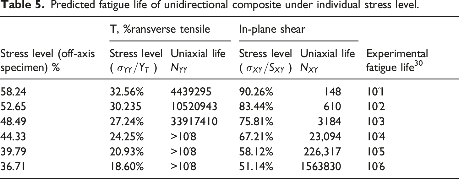
The fatigue resistance of braiding yarn is the critical factor for the fatigue resistance of 3D braided composites.28,29 The braiding yarns in 3D braided composites are mainly subjected to longitudinal tensile stress, transverse compressive stress and shear stress under tensile fatigue loadings. Therefore, in order to effectively simulate the fatigue behavior of 3D braided composites, it is necessary to accurately predict the fatigue life of braiding yarn under coupled stress states. Since it is very difficult to directly study the fatigue behavior of braiding yarn in 3D braided composites, the fatigue properties of unidirectional composite under the same loading condition are generally obtained for the replacement. As exhibited in Figure 6, the variation law of S-N relations of unidirectional composite is attained when the three fatigue stresses are individually loaded.
30
It can be found that the effect of transverse compressive stress on the fatigue life of braiding yarn is very limited when unidirectional composite is subjected to these fatigue loads individually. Therefore, only the effects of longitudinal tensile stress and shear stress on the fatigue life of braiding yarn are considered in the following numerical analysis. Off-axial S-N relationships of unidirectional composite for different stress ratios.
Predicted fatigue life of unidirectional composite under individual stress level.
On-axial fatigue behavior
On-axis S-N curves
The numerical predictions are carried out every 5% stress level interval until the fatigue life exceeds 10^6 or the maximum stress level is below 40%. The predicted S-N curves of 3D braided composites under on-axial tension-tension fatigue loading (stress ratio R = 0.1) are shown in Figure 7. It can be found that the fatigue life gradually increases with the decrease of maximum fatigue stress, and the variation law of specimen 4DS1 and 4DS2 is nearly similar. The fatigue life of specimen 4DS2 is always smaller than that of specimen 4DS2 under the same stress level, which is related to the larger braiding angle of specimen 4DS2. The trends of the predicted on-axial S-N curves here is very similar to that of experimental curves of 3D five-directional braided composites reported by Liu et al.
28
Predicted S-N curves of 3D braided composite specimens under on-axial fatigue tension loadings.
On-axial fatigue damage evolution
The on-axial fatigue damage evolutions of specimen 4DS1 with 55% stress level and specimen 4DS2 with 50% stress level are analyzed here, as demonstrated in Figure 8 and Figure 9. For specimen 4DS1, the main failure modes are yarn L tensile fatigue failure, T compressive shear fatigue failure and matrix cracking. As shown in Figures 8(a) and (b), yarn L tensile fatigue failure and T compressive shear fatigue failure occur at the beginning of fatigue cycles with the same damage locations. However, yarn L tensile fatigue failure almost propagates over the entire yarn after the whole cycles, while T compressive shear fatigue failure is only concentrated in the yarn/yarn contact area. As shown in Figure 8(c), matrix cracking initiates when n = 7.94e4 and propagates rapidly after massive damage of braiding yarn. That is because in this condition resin matrix will bear greater load redistribution. Consequently, yarn L tensile fatigue failure and T compressive shear fatigue failure are the critical factors leading to the final fatigue failure of specimen 4DS1 under on-axial fatigue loading conditions. Damage evolution of specimen 4DS1 under fatigue tension loading (a) Yarn L tensile fatigue failure (b) Yarn T compressive shear fatigue failure (c) Matrix cracking. Damage evolution of specimen 4DS2 under fatigue tension loading (a) Yarn L tensile fatigue failure (b) Yarn T compressive shear fatigue failure (c) Matrix cracking.
For specimen 4DS2, the main failure modes include yarn L tensile fatigue failure, yarn T compressive shear fatigue failure, matrix cracking and yarn Z tensile shear fatigue failure. As exhibited in Figures 9(a) and (b), yarn L tensile fatigue failure and yarn T compressive shear fatigue failure initiate at the beginning of fatigue cycles but the damage locations are different. Unlike specimen 4DS1, the damage propagation range and ultimate damage extent of yarn L tensile fatigue failure and yarn T compressive shear fatigue failure are very similar. Such large propagation range of yarn T compressive shear fatigue failure can be attributed to the larger yarn/yarn contact zones of specimen 4DS2. As can be seen from Figure 9(c), matrix cracking initiates very late when n = 2.51e5 and the propagation of matrix cracking is very limited before the large amount of yarn damage. Matrix cracking is also caused by the greater amount of load redistribution after yarn damage. Therefore, yarn L tensile fatigue failure and T compressive shear fatigue failure are the main triggers for the final fatigue failure of specimen 4DS2 under on-axial loading.
Off-axial fatigue behavior
Off-axial S-N curves
Based on the predicted off-axial static strengths of 3D braided composites, the fatigue behavior of specimens 4DS1 and 4DS2 with different off-axis angles are simulated. The predicted S-N curves of 3D braided composites under off-axial tension-tension fatigue loading (stress ratio R=0.1) are displayed in Figure 10. The variation trend of fatigue life increases with the decrease of stress level of specimen 4DS1 is basically similar under 0, 15 and 30° off-axial fatigue loadings. However, specimen 4DS1 reaches the fatigue limit with a small change of stress level in 45° case, which may be attributed to the greater off-axis angle. This trend is also suitable to specimen 4DS2 but it is not such obvious due to the large braiding angle of specimen 4DS2. Predicted S-N curves of 3D braided composite specimens under off-axial fatigue tension loadings (a) Specimen 4DS1 (b) Specimen 4DS2.
Off-axial fatigue damage evolution
The off-axial fatigue damage evolutions of specimens 4DS1 and 4DS2 are similar to those under on-axial fatigue loadings. Meanwhile, the main fatigue damage modes of braiding yarn at different off-axial loadings are similar to the static damage modes at corresponding off-axis angles. Compared with the damage distribution of braiding yarn in one direction, the overall damage distribution of all yarns can better reflect the off-axial fatigue failure characteristics.
For specimen 4DS1, the main fatigue damage modes of braiding yarn are almost the same in 15° and 0° loading cases, which are yarn L tensile fatigue failure and T compressive shear fatigue failure. The difference is that there is a certain extent of yarn Z compressive shear fatigue failure. In the case of 30° off-axial loading, yarn L tensile fatigue failure is still the main reason for the final fatigue failure, and it is mainly concentrated on the braiding yarns those are close to the direction of off-axial tension loading, as exposed in Figure 11(a). On the other hand, on the braiding yarns that deviate from the off-axial loading direction, it is mainly yarn Z tensile shear fatigue failure, as shown in Figure 11(b). Final damage distribution of braiding yarns under 30°off-axial fatigue tension loading at 60% stress level (a) Yarn L tensile fatigue failure (b) Yarn T tensile shear fatigue failure.
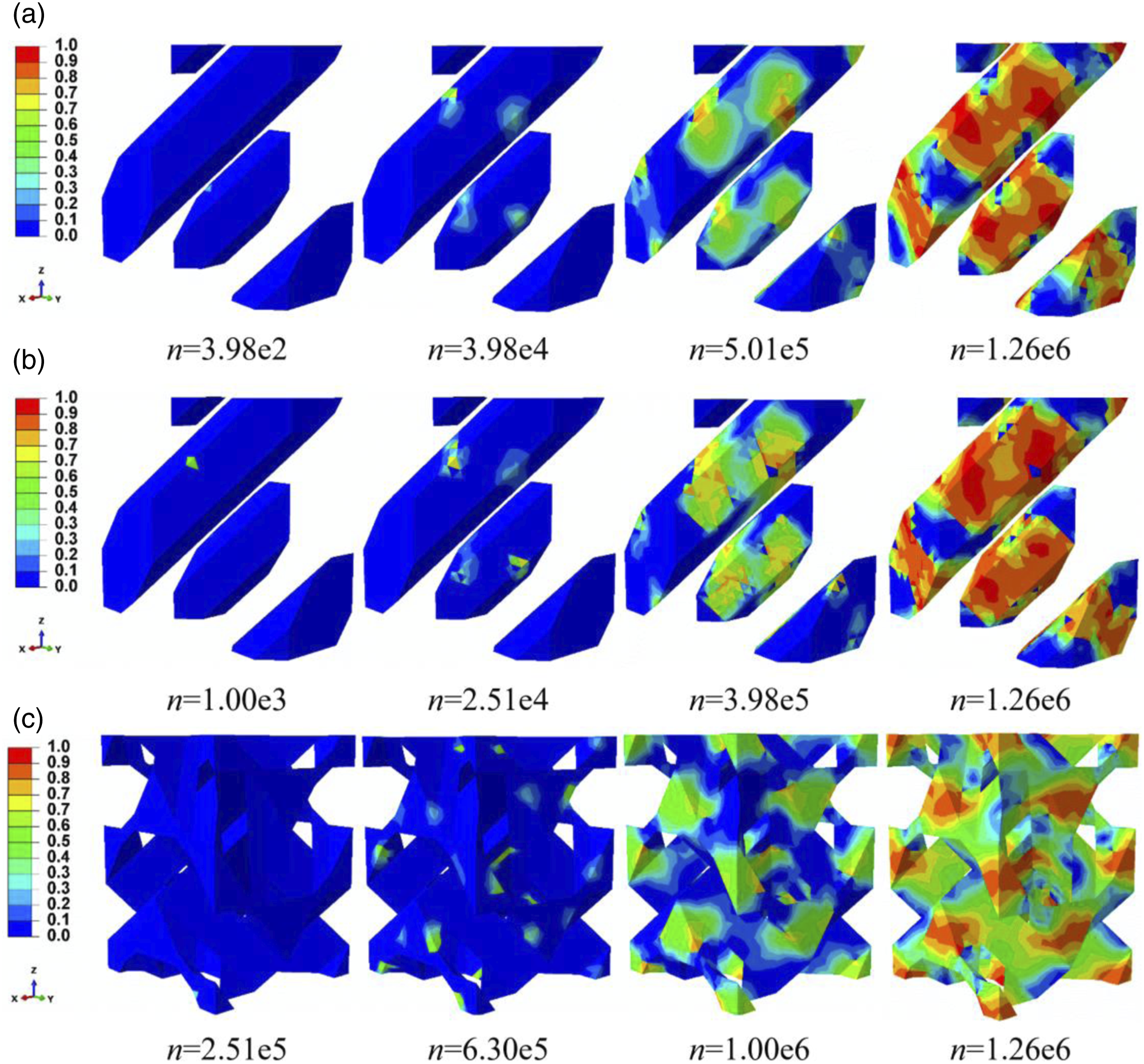
In 45° case, yarn L tensile fatigue failure is very limited, and the main failure mode is transverse tensile shear fatigue failure. The extent of tensile shear failure and its propagation speed in T and Z direction are similar, as shown in Figure 12. Here only the propagation process of yarn Z tensile shear failure is given. It is worth noting that for 45° off-axial fatigue loading, the transverse tensile shear fatigue clearly develops in the yarn/yarn contact zone before fatigue analysis but the propagation rate is very slow. At final fatigue failure, it is still the braiding yarns those are oriented away from the off-axial loading direction show serious damage. Matrix cracking is also one of the main factors for final failure under diverse off-axial fatigue loading conditions. Besides, with the increase of off-axis angle, the failure area gradually shrinks to the yarn/yarn contact zone. Damage evolution of Yarn Z tensile shear fatigue failure of specimen 4DS1 under 45° off-axial fatigue tension loading at 80% stress level (a) n = 1 (b) n = 316 (c) n = 1.25e5 (d) n = 1.58e6
For specimen 4DS2, the main fatigue failure modes of braiding yarn in 15°, 30° and 45° off-axial loading conditions are similar to that in 0° case. There are a large quantity of yarn L tensile fatigue failure, T compressive shear fatigue failure and Z tensile shear fatigue failure, and the propagation of these failure modes are very close. Figure 13 shows the propagation process of yarn Z tensile shear fatigue failure in specimen 4DS2 under 30° off-axial loading with 40% stress level. It can be seen that yarn Z tensile shear fatigue failure occurs before the fatigue analysis starts, but the damage range and extent are very limited. With the continuous fatigue cycles, yarn Z tensile shear fatigue failure propagates slowly along the fiber direction and the overall damage extent gradually increases until the end of fatigue cycles. Matrix cracking in specimen 4DS2 under different off-axial fatigue loading is very similar to that under on-axial fatigue loading. Damage evolution of Yarn Z tensile shear fatigue failure of specimen 4DS2 under 30° off-axial fatigue tension loading at 40% stress level (a) n = 1 (b) n = 7.94e3 (c) n = 1.00e5 (d) n = 1.99e5
Conclusion
In this paper, the PFDM is applied to numerically study the off-axial fatigue properties of 3D braided composites. The meso-scale damage propagation is simulated in detail, the fatigue life is predicted and the damage mechanism is analyzed thoroughly. Several main conclusions can be drawn as follows: (1) The ultimate fatigue failure of 3D braided composites originates from the fatigue failure of braiding yarn. In the on-axis fatigue case, the main damage mode of braiding yarn is L tensile fatigue failure while in the off-axial fatigue cases, the fatigue damage mode of braiding yarn is mainly controlled by the longitudinal shear stress and the main mode is the transverse tensile shear fatigue failure. (2) The off-axial fatigue life of 3D braided composites shows obvious nonlinear characteristics with the stress level. Besides, the braiding angle has a significant effect on the off-axial S-N curves of 3D braided composites. (3) The final damage distribution of 3D braided composites under off-axial fatigue loading is significantly different in braiding yarns with different orientation. The yarn L tensile fatigue failure is generally concentrated in the braiding yarn with a small inclination angle between the fiber direction and off-axial loading direction. On the other hand, the transverse tensile shear fatigue failure is generally concentrated on the braiding yarns with a larger inclination angle between the fiber direction and off-axial loading direction.
The proposed unit-cell based FE model can effectively predict the fatigue damage propagation of braiding yarns in 3D braided composites. However, the limitation is that the fatigue damage simulation of matrix is not accurate enough. In this simulation, matrix cracking appears very late in the whole fatigue cycles when the matrix has to bear a larger load redistribution after yarn damage. In the available experiments of other textile composites,31-33 matrix cracking may appear in the early cycles. The defect effect 34 is not included in the present meso-scale FE model. In the follow-up work, the fatigue properties of matrix and defect effect should be considered to more accurately simulate the fatigue properties of 3D braided composites. Besides, the off-axial fatigue experiments should be conducted to obtain more experimental data for comparison and verification purpose.
Since the PFDM is a common frame and the developed FE modeling strategy is transferable, it provides a suitable reference for the numerical research on the off-axial fatigue problems in other textile composites.
Footnotes
Declaration of conflicting interests
The author(s) declared no potential conflicts of interest with respect to the research, authorship, and/or publication of this article.
Funding
The author(s) disclosed receipt of the following financial support for the research, authorship, and/or publication of this article: This work was supported by the National Natural Science Foundation of China (11832014), Natural Science Foundation of Jiangsu Province (BK20180855) and Research Fund of State Key Laboratory of Mechanics and Control of Mechanical Structures (MCMS-E-0219Y01).