
Abstract
3D braided composites have been increasingly applied in the aerospace, automotive, and other high-tech industries as primary load-bearing structures due to their excellent integrated performance. Evaluation on the failure behavior of 3D braided composites subjected to off-axial loading still remains a challenging topic. We present in this paper a meso-scale finite element (FE) model containing void defects for investigating the off-axial tensile behavior of 3D braided composites. The FE model is verified and the effects of porosity are discussed in on-axial tensile conditions, and then it is executed to predict the mechanical response in general off-axial tensile cases. The strength properties of 3D braided composites, and more importantly the progressive damage behavior under typical off-axial loadings, are analyzed in detail. It is found that the off-axial tensile strength and corresponding failure mode of 3D braided composites are mainly affected by the braiding angle of specimen. The proposed FE modeling provides an appropriate reference for the numerical study of void defects and off-axis load problems in other textile composites.
Keywords
Introduction
3D braided composites are a new type of textile composites, which are mainly formed by curing fiber reinforcement preform with resin matrix through Resin Transfer Molding (RTM) process. The near-net-shape preform structure of 3D braided composites provides outstanding out-of-plane performance over 2D composite structures, especially the better inter-laminar fracture toughness and higher impact damage tolerance. In the past two decades, 3D braided composites have become an important structural material and been increasingly employed as truss structure, beam structure, joint structure, etc., in the aerospace, automotive, energy, and other high-tech industries for the weight reduction and primary load-bearing purpose.
3D braided composites own complicated microstructure and show intensive anisotropy, which results in considerable difficulties for the mechanical properties evaluation and damage mechanism analysis. However, the physical experiment is rather costly and hardly to characterize the mechanical behavior of composite materials with different parameters. On the other hand, less limitation happens in the numerical simulation for performance assessment.1-4 Accordingly, FE modeling, especially the unit-cell-based meso-scale simulation approach, is often preferred by the researchers to study the complex mechanical response of 3D braided composites.5-9
Voids, regions unfilled with fibers and matrix, are inevitable during the RTM process. Voids can also be regarded as the fourth constituent of carbon fiber-reinforced resin matrix composite except fiber, matrix, and interface. A comprehensive review about the formation, characterization, and mechanical effects of void defects in fiber-reinforced composites can be found in Ref.[10]. After applying new technology like X-ray micro-computed tomography, more insights into the detailed characteristics of voids in composite materials have been obtained. 11 For 3D braided composites, some recent studies have shown that the void defects lead to the degradation of stiffness properties12-15 and highly affect the strength and damage process of composite structures.16-18 Therefore, voids, the major manufacturing defects, should be involved in the meso-scale simulation of 3D braided composites.
3D braided composites aim to be employed as primary load-bearing structures in the high-tech industries and they are ordinarily subjected to complex load states during service. Off-axis loading is a most typical case of complex loads. Therefore, the research on mechanical behavior of composite structures under off-axial loading can be regarded as the base of solving other related problems under complex load conditions. The current works on off-axial behavior of composite structures are mainly focused on unidirectional composites and composite laminates.19-22 Few studies have been conducted on analyzing the off-axial strength and failure of woven composites based on progressive damage modeling strategy.23-25 Lu et al. 23 and Zhou et al. 24 conducted a two-step progressive damage analysis to characterize the damage behaviors of 2D and 2.5D weave composites subjected to different off-axial loading cases. Wang et al. 25 presented a meso-scale FE model to simulate the off-axial tensile and compressive damage evolution of twill woven composites. However, up to now, the off-axial mechanical properties study of 3D braided composites has not been reported in the available literatures.
Due to the lack of thorough understanding of mechanical response under complex load states, 3D braided composite structures are always over-safely designed and the light-weight superiority cannot be maximized. The primary objective of this work is to investigate the off-axial tensile behavior of 3D braided composites by a robust meso-scale FE model containing void defects. The effects of voids on the on-axial mechanical properties of specimens with typical braided angles are firstly discussed and the proper porosities are selected. Then, the stress–strain curves of specimens under different off-axial loadings are simulated and the corresponding strength properties are predicted. Finally, the progressive damage evolutions of specimens under typical off-axial loadings are provided and the damage modes and failure mechanism are thoroughly analyzed. This work provides a transferable approach for numerical analysis on void defects and off-axis load problems in other textile composites.
Progressive damage model
Progressive damage simulation based on unit-cell model is an effective numerical approach for strength prediction and damage analysis of textile composites, which generally involves the constitutive relations of constituents, damage initiation criterion, and damage evolution scheme.
Damage models of braiding yarn and matrix
Damage initiation criteria
3D Hashin failure criteria, 26 capable to identify the possible failure modes of braiding yarns, are employed and formulated as
Yarn tensile failure in L direction

Yarn compressive failure in L direction

Yarn tensile and shear failure in T and Z direction

Yarn compressive and shear failure in T and Z direction

In the above equations, φ is the index of each damage failure criterion;
Maximum stress criteria, implemented to describe the damage initiation of matrix, are given as


Damage evolution scheme
The damage state of braiding yarn and matrix can be characterized by Murakami damage model,
27
namely


Here,
The braiding yarn is considered as transversely isotropic material and the three principal damage variables are determined by


The matrix is regarded as isotropic material and the damage variables are determined by

Linear damage evolution is adopted for each damage mode, namely
29


Here,

Damage model of interface
Interface is known as a vital constituent in 3D braided composites. In view of this, interface debonding, a typical failure mode, should be introduced in the meso-scale FE modeling. It is known that the interface debonding is always happened under mixed-mode condition. Therefore, zero-thickness cohesive element, ruled by a mix-mode bilinear traction-separation model, is utilized here to simulate the damage behavior of yarn/yarn and yarn/matrix interface.
To involve the three interface pure modes I, II, and III together, the effective relative displacement, δm, is defined as

A quadratic nominal stress criterion
30
is implemented to determine the interface damage initiation displacement

An interactive power law of energy
30
is implemented to determine the interface final failure displacement

Due to the irreversibility of interface damage, the maximum relative displacement in the loading process,

Linear damage evolution is also adopted for interface and the damage variable d is determined by

Finite element modeling
Unit-cell structural model
In this work, a reasonable unit-cell structural model, developed by Xu and Qian,
6
is adopted to investigate the mechanical behavior of 3D braided composites by meso-scale FE modeling strategy. The braiding yarns are presumed to be straight and stay in surface contact state caused by mutual squeeze.
31
The cross-section of braiding yarn is assumed as octagon with an inscribed ellipse, as illustrated in Figure 1(a). The structural model of unit-cell is displayed in Figure 1(b). Meso-scale structure of 3D braided composites (a) SEM micrograph
31
(b) Structural model of unit-cell (c) Geometrical model of unit-cell.
Generally, the interior braiding angle γ is difficult to be measured. However, as shown in Figure 1(c), the angle of inclination of the yarns on the surface of composite, that is, the braiding angle α, can be measured easily, one has

For the major radius a and minor radius b of the inscribed ellipse, one has

The cross-sectional area of braiding yarn S
b
can be computed by

For the width W, thickness T, and height h of the unit-cell, we have


Based on equations 23–27, the fiber volume fraction V
f
of 3D braided composites can be obtained by

Periodic boundary conditions
To reflect the repeating nature of unit-cell and guarantee the displacement compatibility and traction continuity conditions, periodic boundary conditions
32
should be enforced to the meso-scale FE model. The displacements at the paired parallel boundaries of unit-cell can be given by


The difference of the above two equations can be expressed as below

The explicit expression of periodic boundary conditions, equation (31), can be conveniently applied by nodal displacement constraint equations available in ABAQUS software, as given in Ref.[33].
Mesh discretization and introduction of void defects
In order to facilitate the enforcement of periodic boundary conditions, periodic meshing of unit-cell is necessary. As shown in Figure 2(a), with the consideration of admirable geometry adaptability, C3D4 tetrahedral element is applied here for discretization of braiding yarns and matrix. For such complicated unit-cell structural model, it is difficult to directly introduce the cohesive elements in the yarn/yarn and yarn/matrix zones by mesh tools. In this study, a pre-compiler program about COH3D6 cohesive element generation is written and executed to adjust the INP file of the meso-scale FE model based on ABAQUS software. Zero-thickness cohesive elements generated by this approach in the yarn/yarn and yarn/matrix interfaces are displayed in Figure 2(b). It should be pointed out that the mesh sensitivity analysis had already been conducted here and the results show that the following mesh discretization is fine enough to attain convergence solutions. Discretization of unit-cell model (a) Braiding yarns and matrix (b) Interface (c) Introduction of void defects.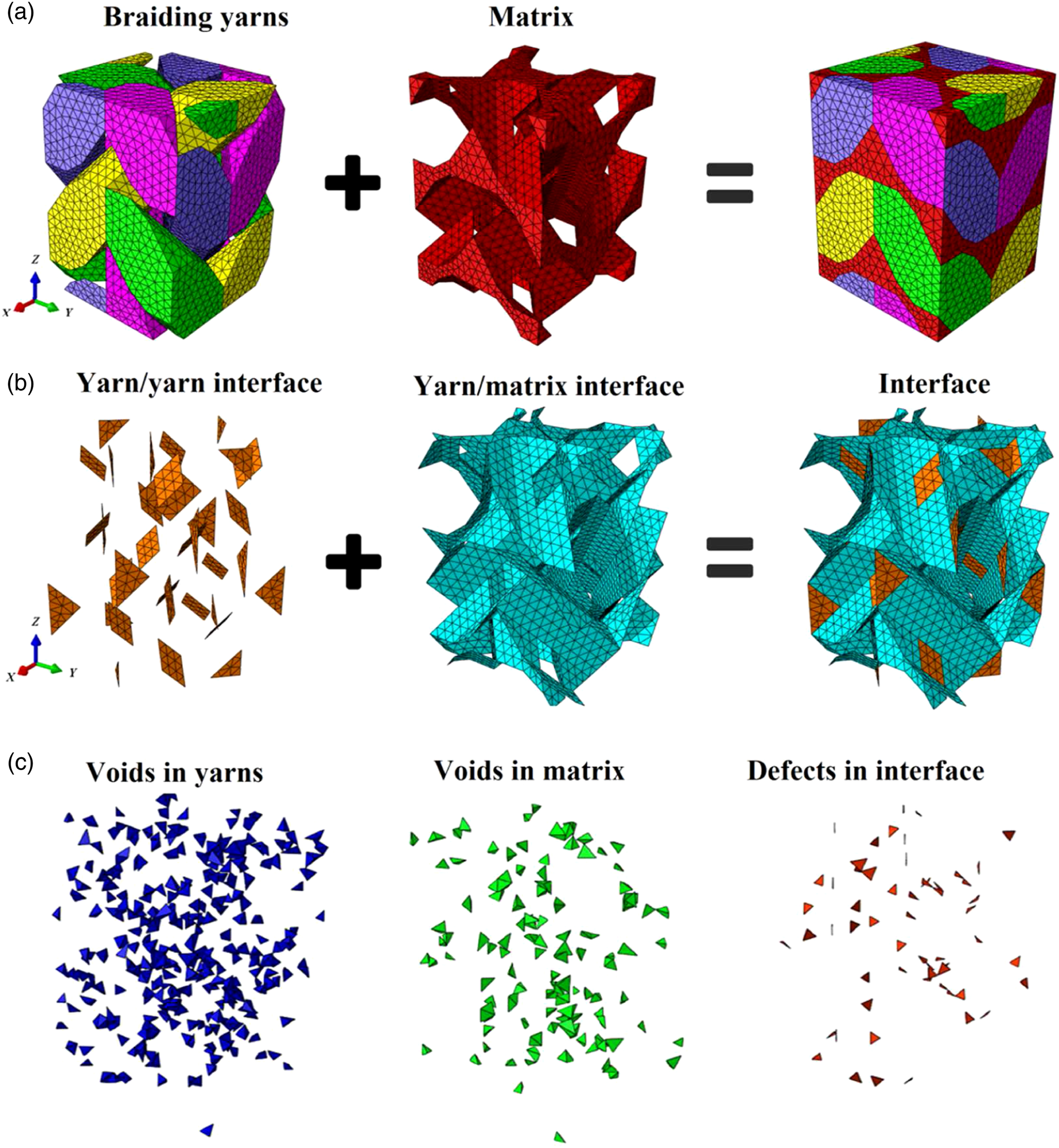
Void defects are inevitable in the manufacturing process of 3D braided composites. In this paper, the effects of porosity on the mechanical properties of 3D braided composites are evaluated by introducing the void defects into the meso-scale FE model. Considering that the voids are randomly distributed in the specimen, a pre-compiler program based on random function is written to randomly select the related elements of three constituents in the FE model, and the specific porosity (1% as exhibited in Figure 2(c)) and properties of voids (extremely small stiffness) are assigned to these selected yarn, matrix, and interface elements to simulate the void defects in the three constituents of 3D braided composites. Besides, it should be pointed out that the shape of void cannot be involved in the proposed FE model.
Off-axial loading and stress state analysis
In on-axis case, periodic boundary conditions are carried out by applying on-axial displacement loads. Similarly, in off-axis condition, 3D braided composites can be considered to be loaded in both longitudinal and transverse directions and shear stress appears in the loading plane. Displacement loading mode is also adopted to apply the off-axial loads to the unit-cell model.
For the local and global coordinate system, the spatial stress transformation Matrix A can be expressed as

The spatial strain transformation matrix is the transposition of spatial stress transformation matrix, denoted as AT. The strains in the local coordinates can be transformed to the strains in the global coordinates by

For in-plane off-axial loading of 3D braided composites, the off-axial angle is defined as the angle between material longitudinal direction and loading direction. In this case, we have
After transforming the off-axial strains to the strains in the global coordinates, the corresponding displacement components are obtained and then they will be employed to the unit-cell model based on periodic boundary conditions. The normal stress and shear stress of each principal direction in the global coordinate can be obtained by

Then, the stress in the global coordinate can be transformed into the stress in the local coordinate by

Numerical results and analysis
Process parameters of the specimens and corresponding structural parameters of the unit-cell model.

Material properties of carbon fiber and resin matrix 7 .

Properties of interface cohesive elements 7 .

On-axial mechanical behavior
The predicted on-axial stress–strain curves of specimens are obtained by meso-scale FE simulation considering different porosities, as shown in Figure 3. With the increase of porosity, the tensile strength of 3D braided composite specimens 4DS1 and 4DS2 overall decreases gradually. For 3D braided composites, the strength of specimen 4DS1 with small braiding angle mainly depends on the braiding yarn, while the strength of specimen 4DS2 with large braiding angle is determined by both the yarn and matrix. After the void defects are introduced into the unit-cell of specimen 4DS1, the fracture of braiding yarn will cause the material to lose its bearing capacity rapidly. With the increase of porosity, the longitudinal strength of braiding yarn decreases gradually thus leads to the strength decrease of specimen 4DS1. On the other hand, for specimen 4DS2, the fracture of braiding yarn hardly occurs before the material loses its load-bearing capacity. After introducing the void defects, the effect of porosity on the strength of matrix is significantly less than that on braiding yarn. Therefore, compared with the specimen with large braiding angle, the tensile strength of specimen with small braiding angle is more susceptible to the porosity. On-axial stress–strain curves of specimens with different porosities (a) Specimen 4DS1 (b) Specimen 4DS2.
From Figure 3, it is interesting to find that the tensile strength of specimen 4DS1 with porosity 2% surpasses the counterpart with porosity 1.5%. Such phenomenon can be attributed to the different spatial distribution of void defects in the unit-cell model. Considering the difference in void distribution, we have carried out five sets of numerical simulations of specimen 4DS1 for the same porosity 2.0%. The predicted strengths of specimen are 422.92, 424.45, 428.40, 428.74, and 411.93, respectively. It can be concluded that the spatial distribution of void defects has a certain influence on the predicted mechanical properties of 3D braided composites even with the same porosity. For specimen 4DS2, the effect of porosity on the mechanical properties is much smaller compared with that on specimen 4DS1.
On-axial tensile strengths of specimens with different porosities.

Off-axial mechanical behavior
Stress–strain curve
Figure 4 illustrates the off-axial stress–strain curves of specimens 4DS1 and 4DS2 with porosity 1.0%. For specimen 4DS1, the off-axial tensile strength increases slightly when the off-axis angle increases from 0° to 15° while it decreases significantly with the further increase of off-axis angle from 15° to 60°. At off-axis angle 60°, the tensile strength is the lowest and about 37% of that in 15° case while the fracture strain is 1.45 times of that at 15°. For specimen 4DS2, the trend of its stress–strain curves is different to that of specimen 4DS1. The off-axial tensile strength of specimen 4DS2 increases gradually when the off-axis angle increases from 0° to 45°. The tensile strength in 45° case is the highest, which is almost the twice as that in 0° case. The off-axial tensile strength decreases obviously when the off-axis angle increases from 45° to 60°. Off-axial stress–strain curves of specimens with porosity 1.0% (a) Specimen 4DS1 (b) Specimen 4DS2.
Off-axial tensile strengths and fracture strains of specimens.


Predicted tensile strength of specimens under tensile loading with different off-axis angles.
Damage evolution mechanism analysis
The main damage modes of specimens 4DS1 and 4DS2 both include the interface debonding, matrix cracking, and yarn breaking, but the difference between the two specimens is mainly reflected on the damage mode of braiding yarn. Under different off-axial tensile loadings, for specimen 4DS1, the main damage modes in L and Z directions are L tensile failure and Z tensile shear failure. Besides, the main damage mode in T direction is T compressive shear failure at 15° and 30° off-axis angle and T tensile shear failure in 45° and 60° cases. For specimen 4DS2, the main damage modes are T shear failure and Z tensile shear failure. The shear failure in T direction changes gradually from T compressive shear failure to T tensile shear failure with the increase of off-axis angle and both of them occur with large quantities in 45° case. Moreover, L tensile failure in specimen 4DS2 happens only in 45° and 60° off-axial tensile loading conditions.
Since the damage mechanisms of 3D braided composites under off-axial loading are very complex and there are many off-axis angles considered in the simulation, for specimen 4DS1, only the damage evaluation process of interface debonding, yarn L tensile failure, and matrix cracking under 15° off-axial tension are given (Figure 6); for specimen 4DS2, only the damage evaluation process of interface debonding, yarn Z tensile shear failure and matrix cracking in 45° case are presented (Figure 7). Damage propagation process of typical damage modes in specimen 4DS1 under 15° off-axial tension (a) Interface debonding (b) Yarn L tensile failure (c) Matrix cracking. Damage propagation process of typical damage modes in specimen 4DS2 under 45° off-axial tension (a) Interface debonding (b) Yarn Z tensile shear failure (c) Matrix cracking.

As shown in Figure 6, interface debonding appears first in the yarn/yarn contact regions near the top of unit-cell model. Then, the interface debonding mainly happens in the yarn/yarn contact regions inside the unit-cell. During the loading process, interface debonding mainly develops along the fiber axial and transverse directions but the propagation rate is obviously higher than those of yarn L tensile failure and matrix cracking. Yarn L tensile failure initiates when off-axial tensile strain
Seen from Figure 7, the evolution process of interface debonding in specimen 4DS2 is basically similar to that in specimen 4DS1. Interface debonding also appears first in the yarn/yarn contact regions near the top of unit-cell and then expands to the yarn/yarn contact regions near each surface of the unit-cell. With the further off-axial tensile loading, interface debonding expands to the interior of the unit-cell along the fiber direction. Yarn Z tensile shear failure initiates in the middle of the yarn and expands to the whole yarn along the fiber direction rapidly. The propagation rate is the fastest among these three damage modes, and its damage state is also the most serious. Matrix cracking appears first in the yarn/yarn contact regions near the top surface and expands to the interior of the unit-cell model along the fiber direction gradually under the off-axial loading. The propagation rate of matrix cracking in the whole loading process is gradually accelerated.
Conclusions
In the present work, we have successfully developed a nonlinear meso-scale FE model containing void defects to analyze the off-axial tensile behavior of 3D braided composites. This work shows that FE simulation is the most convenient and effective method to investigate the damage response of 3D braided composites under off-axial loading events. Some conclusions can be drawn as follows: 1. The tensile strength of 3D braided composites with void defects decreases gradually with the increase of porosity under on-axial tension loads. Compared with the specimen with large braiding angle, the tensile strength of the specimen with small braiding angle is more susceptible to the porosity; 2. There is a specific off-axis angle for each specimen at which the predicted off-axial tensile strength of 3D braided composites reaches the peak value. For porosity 1.0%, the predicted maximum off-axial tensile strength of specimen 4DS1 appears at 5°while it appears at 46.4° for specimen 4DS2. The specimen with small braiding angle is suitable for the off-axial load with small off-axis angle while the specimen with large braiding angle is on the contrary; 3. The braiding angle has obvious influence on the yarn failure mode of 3D braided composites under off-axial tensile loading. The main damage modes of yarn in specimen with small braiding angle are yarn L tensile failure and Z tensile shear failure while those of specimen with large braiding angle are T tensile shear failure and Z tensile shear failure. Interface debonding and matrix cracking are both the main failure modes of 3D braided composites under off-axial tension loads; 4. The present numerical model is an effective manner to perform off-axial loading simulation of 3D braided composites. Moreover, the modeling strategy is general and robust, which can provide a transferable routine for numerical investigation of void defects and off-axis load problems in other textile composites.
Footnotes
Declaration of conflicting interests
The author(s) declared no potential conflicts of interest with respect to the research, authorship, and/or publication of this article.
Funding
The author(s) disclosed receipt of the following financial support for the research, authorship, and/or publication of this article: This work was supported by the National Natural Science Foundation of China (11832014), Natural Science Foundation of Jiangsu Province (BK20180855) Research Fund of State Key Laboratory of Mechanics and Control of Mechanical Structures (Nanjing University of Aeronautics and astronautics) (MCMS-E-0219Y01).