
Abstract
The paper deals with development and characterization of 3D sandwich composite structures reinforced with newly-designed multi-cell flat-knitted spacer fabrics in terms of compressive behaviour and Poisson’s ratio. Multi-cell spacer knitted preforms was produced on a computerized flat knitting machine. 3D composite samples with three different cross-sectional geometries were prepared via vacuum assisted resin transfer moulding method. Quasi-static compressive experiments were carried out on the prepared 3D composite samples. The Poisson’s ratio of re-entrant 3D knitted composite varied between -6 and -1, which clearly points to existence of auxetic behaviour of the samples. The re-entrant 3D composites also demonstrated the highest initial slope and area under the compression force-displacement curve than spear-head or hexagonal composite structures which refer to higher energy absorbing capacity. The Poisson’s ratio of 3D regular hexagonal knitted composites at small strain was usually 4 which gradually decreased to 1.6 as the exerted compressive strain increased. Additionally, 3D spear-head knitted composite having zero Poisson’s ratio was also developed.
Introduction
Auxetic structures are materials with negative Poisson’s ratio. Advantages such as enhanced strength and fracture toughness, higher shear modulus and energy absorption as well as damping improvement of auxetic materials have gained the interest of various scientific disciplines [1,2]. These advantages have rendered auxetic materials for wide spectrum of applications including apparels, technical textiles, aerospace, protective materials and bio-medical industry. In general, auxetic structures can be found in form of natural materials, polymeric, textiles and composites [3–6].
Among various textile manufacturing techniques, knitting technology is the most versatile technique that can produce complex plane and 3D auxetic structures [7]. Weft-knitted auxetic fabrics can be produced using various auxetic designs such as foldable and re-entrant hexagon structures, or rotating rectangles [8–11].
Auxetic composites in comparison with non-auxetic composites possess proven enhanced properties such as impact resistance, energy absorption capacity and indentation resistance [12–15]. Despite vast experimental studies conducted on auxetic weft knitted fabrics, the amount of conducted investigation on auxetic knitted fabrics reinforced composites are rather scarce. Steffens et al. [16,17] evaluated the composites reinforced with plane auxetic weft-knitted fabrics knitted using high-tenacity para-aramid and polyamide fibres. It was concluded that not only the composite samples retain their auxeticity features, but also auxetic behaviour of the samples is significantly influenced by the type of fibres used during knitting. Boakye et al. [18] investigated the compressive characteristics of auxetic Kevlar arrow-head tubular knitted composite under quasi-static compression loading condition. It was concluded that the energy absorption performance of the auxetic knitted composites is greatly influenced by the structure auxeticity.
More recently, 3D composites reinforced with multi-cell flat knitted spacer fabrics have been developed [19–22]. According to Figure 1, conventional multi-cell flat-knitted spacer fabrics are commonly composed of at least two inter-connected surface layers which demonstrate non-auxetic behaviour while exposed to compressive loading [23–26]. Based on authors’ knowledge, the fabricating technology of three-dimensional auxetic composites reinforced with multi-cell spacer knitted fabrics is not yet to be fully developed. Hence, the present work principally concentrates on development and auxetic characterization of 3D composite structures reinforced with newly-designed multi-cell flat-knitted spacer fabrics, using three knitted structures with different cross-sectional geometries produced on an electronic flat knitting machine.
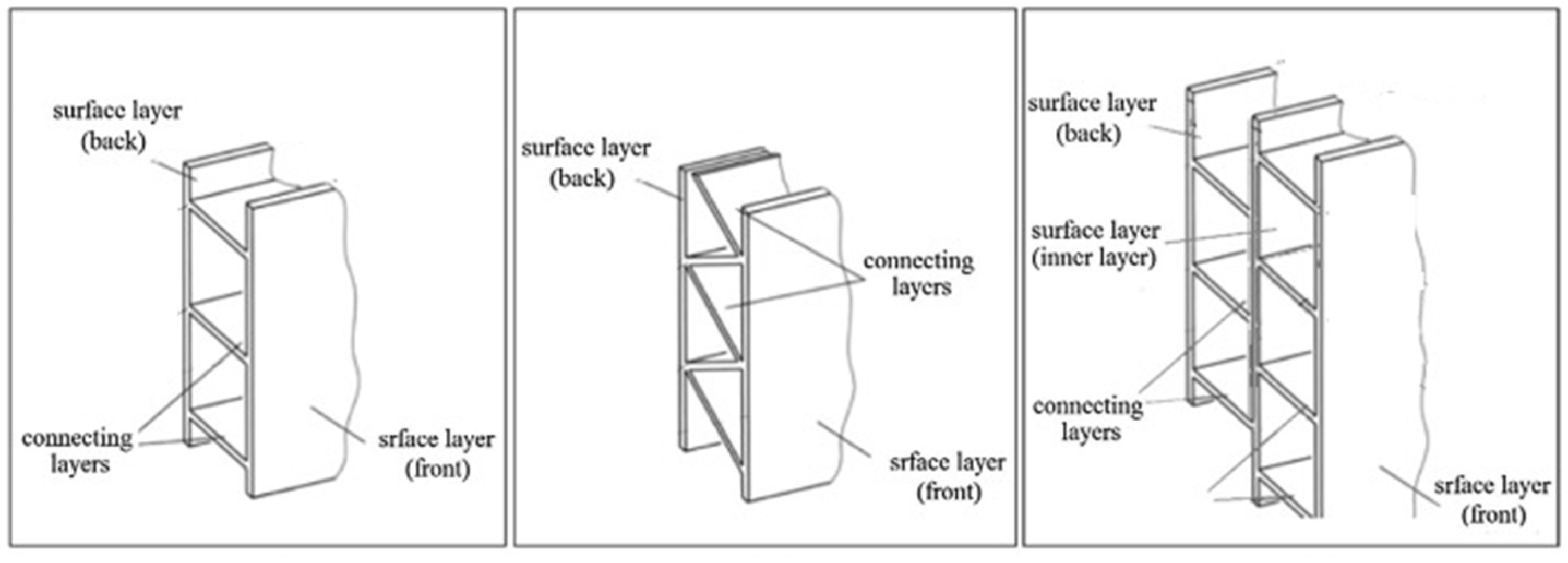
Multi-cell flat-knitted spacer fabrics with different structures.
Material and methods
Advances made in flat knitting technology, has culminated in successful use of this technology in production of 3D multi-cell spacer preforms [27,28]. Figure 1 depicts cross sectional possibilities of 3D preforms that can be knitted on a flat knitting machine. In this research using a computerized flat knitting machine (Stoll CMS400, E5, equipped with latch needles, 4 systems) and four-plied 100Tex multifilament texturized polyester yarns (elastic modulus: 1.11 GPa, elongation at break: 27.68%, breaking force: 19.093 N), multi-cell spacer knitted preforms with three different cross-sections geometries were prepared. The required knitting sequence for production such structures is principally similar to those utilized for preparation of conventional 3D multi-cell spacer preforms. Figure 2 shows the 15 knitting sequences and notation used for knitting of various layers, respectively. The knitting sequences are as follows: (1) Layer “a” is knitted using by the odd needles of the front -bed. (2 and 3) Layer “b” is also knitted by the even needles of the front -bed. Prior to this knitting step, in order to connect the layer “a” and layer “b”, all needles of the front -bed knit. (4 and 5) Layer “c” is knitted by the even needles of back -bed. Inter-connection of the layer “b” and the layer “c” is carried out by transferring of the loop of the even needles of back -bed to their counter parting needles of front -bed. (6) The layer “d” is knitted by the odd needles of the back -bed. (7 and 8) The layer “e” is knitted by the even needles of front -bed, and even needles of front -bed are transferred to their counter parting needles of back -bed. (9 and 10) Then two separate layers (“f” and “g”) are knitted by the even needles of front needle-bed and by the odd needles of back needle-bed. (11 and 12) Two courses are simultaneously knitted on all needles of both needle-beds. These courses connect the layer “f” and layer “g” together. (13, 14 and 15) In the final step, knitting is continued by the odd needles of the back -bed and the even needles of the front-bed to produce the layer “h” and the layer “i”. Then the transfer of the loops of the even needles of back -bed to the even needles of front –bed occurs to connect these layers. With this stage, a full repeat of knitting sequence for producing the 3D structure is completed. Figure 3 depicts 3D preforms knitted on flat knitting machine. Number of courses and wales per cm were measured as 4.28 and 2.85, respectively.

(a) The knitting sequence of the various layers. (b) 3D structure knitting notation.

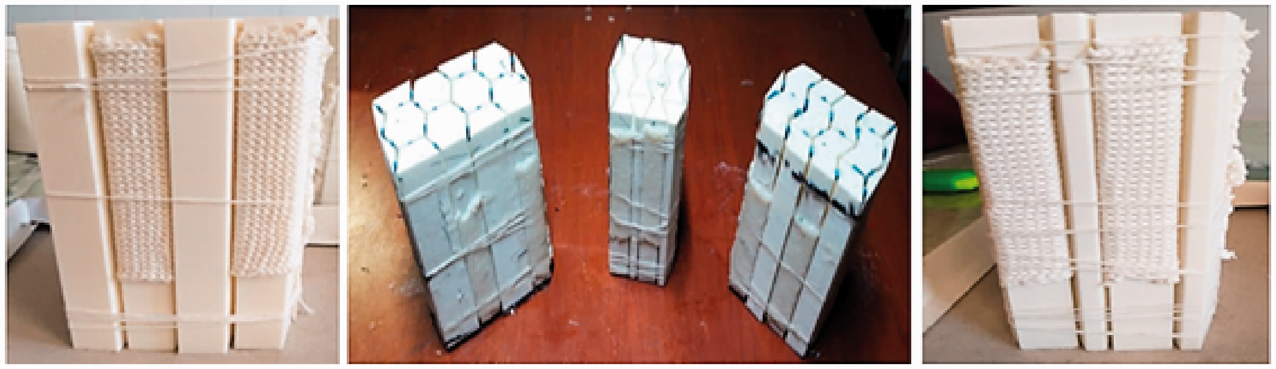
Top-view of 3D preforms knitted on flat knitting machine.
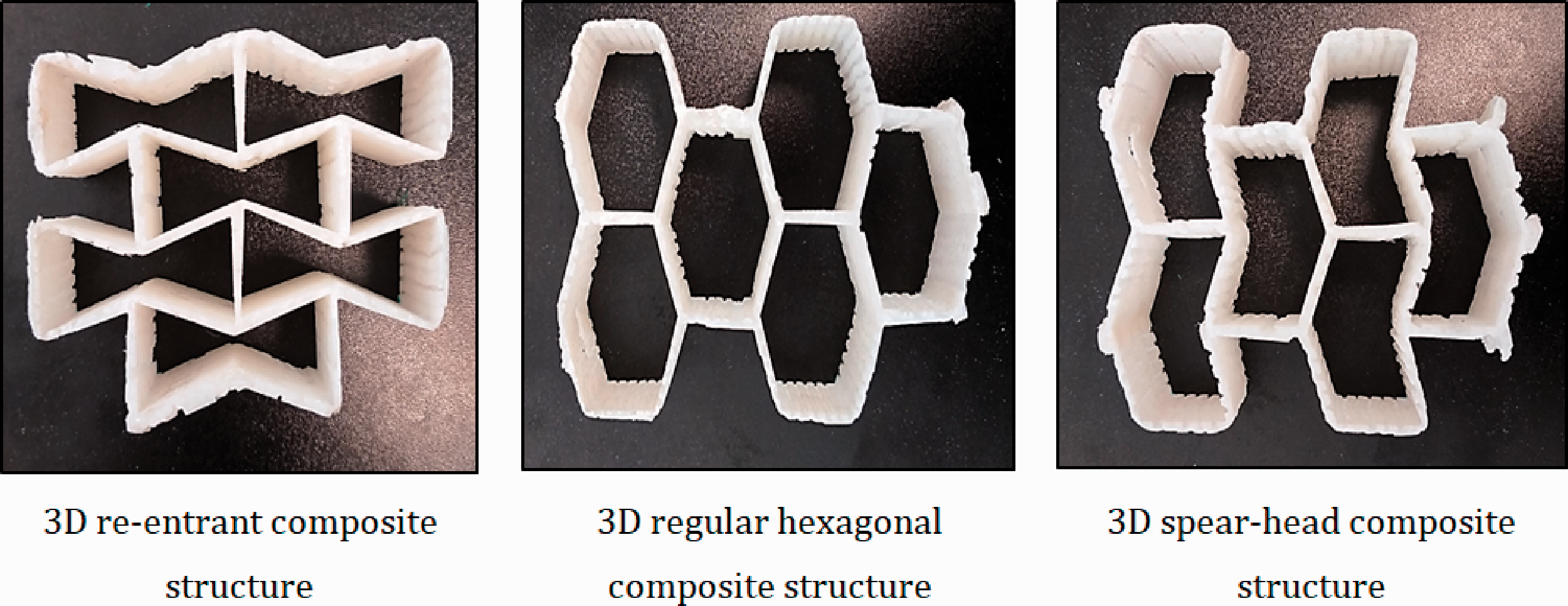
3D composite samples with three different cross-sectional geometries; namely re-entrant, regular hexagonal and spear-head were prepared. Figure 4 shows the geometries and dimensions of the 3D composites.

Geometries of the 3D composites. (a) Re-entrant; (b) regular hexagonal; (c) Spear-head.
The vacuum assisted resin transfer method (VARTM) is a well-known open-top mold composite manufacturing method in which a vacuum bag is attached to the top of the mold and vacuum is applied to assist the continuous flow of thermoset resin from one side of the mold to the other. This method is capable to fabricate composites parts with complex geometries. These complex 3D geometries can be achieved using purposely designed and dimensioned inserts fabricated by 3D printing technique are shown in Figure 5.

The purposely desgined inserts.
Epoxy resin EP411 and hardener H15 purchased from DCM Company were mixed in 100pbw:10pbw ratio. Specifications of the resin used for preparation of the samples are given in Table 1.
Characteristics of the used epoxy resin.

Infusion of 3D-knitted preforms with resin was carried out through the following steps: the produced 3D knitted fabrics (Figure 2) are multi-layers and open at the both sides. The inserts fill the voids between the layers of the knitted fabric prior to application of vacuum by a negative pressure pump (Figure 6). In order to facilitate the removal of inserts after curing operation, the inserts were smeared with releasing wax prior to insertion. 3D composite samples with inserts. 3D composites 4-step manufacturing route. covering of the fabric samples with peel-ply and mesh layer (Figure 7-(1)); installation of resin transferring pipe (Figure 7-(2)); covering the mesh layers with plastic bag and application of vacuum (Figure 7-(3) and Figure 7-(4)); the inserts can be easily separated from the produced composite by a slight impact.

Composite samples were cured at room temperature for 48 hours. In order to improve mechanical properties of the samples, the samples were post-cured for 3 additional hours in an oven at 80 °C. Figure 8 shows the produced composite samples.
Actual 3D knitted composites.
Fibres volume fraction 
Where,
Despite low void formation ability of the VARTM method, possibility of void formation using this method during composite fabrication must not be underestimated [21]. Value of void content in the composite is given by equation (2): 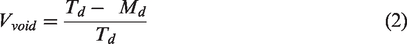
Where, Td and Md are the theoretical density and the experimental densities of the composite samples respectively. Based on equation (2), void contents of composite samples re-entrant, regular hexagonal and spear-head were found to be 0.92%, 1.05%, and 0.96%, respectively.
Poisson’s ratio measurement of samples
Quasi-static compressive experiments were carried out using a universal tensile tester (Zwick 1446, Germany) at constant structural strain rate of 2 mm/min. Tests were carried out at constant temperature and relative humidity of 23 C ± 3 °C and 50% ± 5%, respectively. Poisson’s ratio is the ratio of transverse or lateral to the longitudinal or axial strains. Measurement of Poisson’s ratio is usually carried out using extensometers or strain gauge on a tensile tester. The use of strain gauges is often not compatible with 3D structures due to mounting of the strain gauge and costs [29]. In this study, a non-contact and easy to use digital image correlating technique was utilized to calculate the strains and ultimately the Poisson’s ratio of the 3D composite samples. The measurement was carried out by placing of a camera in front of the sample at a suitable distance for the area to be measured, and the captured images during compression process were analysed. To measure the Poisson's ratio, special points were marked on the corners of the composite’s structural cell. The distance between these points was measured in the horizontal and vertical directions during the loading process by a written program in Matlab software environment. The Poisson's ratio was calculated based on the ratio of lateral to axial strain. Figure 9 shows the compression test and a captured image during deformation.
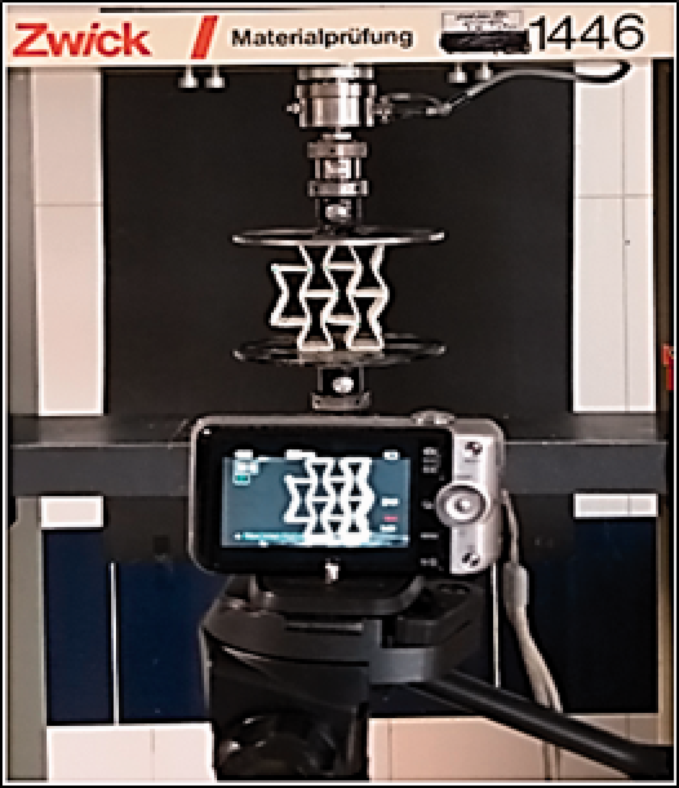
Poisson’s ratio measurement of samples using compressive loading.
Results and discussions
Figures 10 to 12 illustrate the deformation process of re-entrant, regular hexagonal and spear-head 3D composite structures in different indenter displacements. Comparison of the captured images reveals the effect structural cross-section geometry on composite behaviour under the applied compressive force.
Based on Figure 10, it can be concluded that the 3D the re-entrant composite behaves as an auxetic structure because it contracts both longitudinally and laterally when subjected to compression load. Figure 10 illustrates that the diametrically located corners of the cell structure containing re-entrant cells under compression loading condition, due to rapid buckling of the cell walls and concentration of stress on mid-point of the walls tend to get closer together. This amounts to auxetic effect due to retraction of the structure in direction perpendicular to the compressive loading direction. Occurrence of the compressive strain, forces the wall to shrink towards the centre point of re-entrant cells. Further insight into the deformation process proves the rotation of the re-entrant cells in opposite direction.
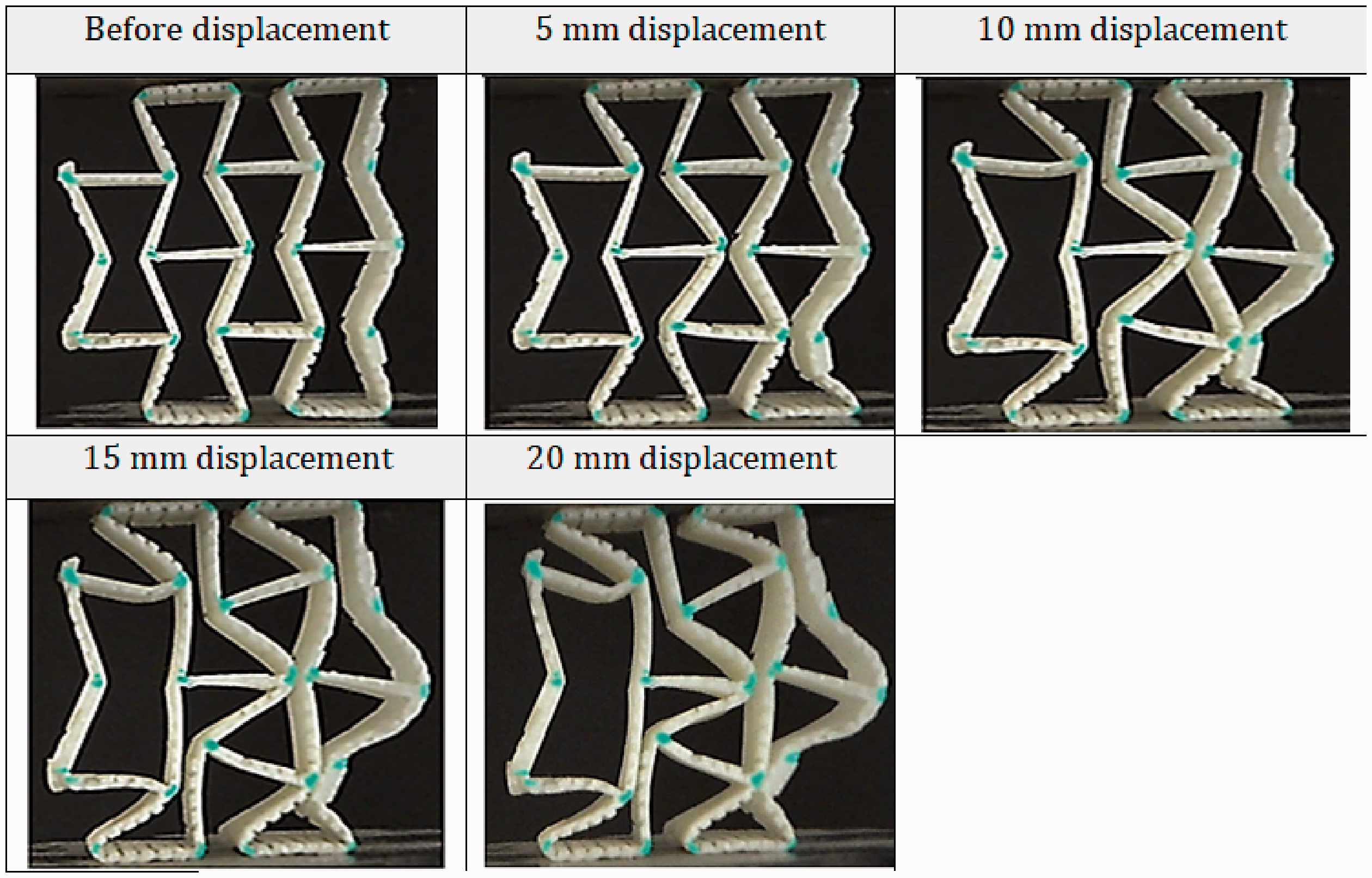
Compressive behavior of re-entrant composite structure.
Figure 11 shows that in structure containing regular hexagonal cells under compression loading condition, the distance between diametrically located corners of the central cell increases. This is due to rapid buckling of the cell walls and concentration of stress on diametrically located corners.
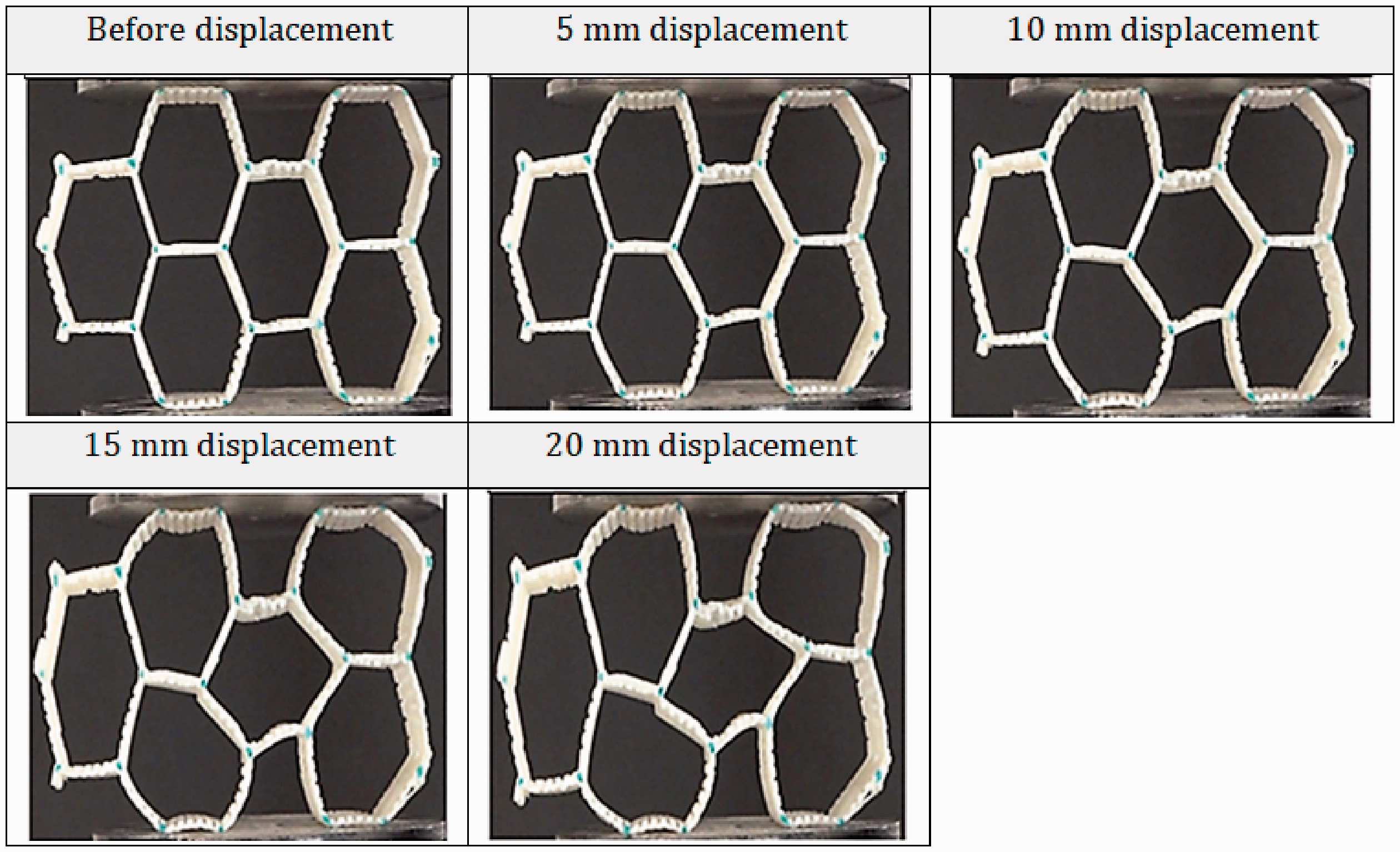
Compressive behavior of regular hexagon composite structure.
This expanding behaviour is in contrast to the compressive behaviour of re-entrant structure due to the different angle of the cell walls to horizontal axis. Thus, the observed lateral expansion and axial contraction of hexagonal structure under compressive loading.
Figure 12 demonstrates the deformation of the spear-head knitted composite at different displacements with the spear-heads cells point in opposite directions. Such arrangement of spear-heads results in equilibrium of forces applied to a central cell by the two adjacent cells placed on each side of the central cell. Under this circumstance the central cell can be assumed to remains intact. Up on a displacement of 10 mm, the mid-points of the central cell walls gradually diverge. This may be considered to be the inauguration of the fracture in the composite structure. However, under actual circumstance dimensions of the central cell remain acceptably unchanged up to a displacement of 15 mm.
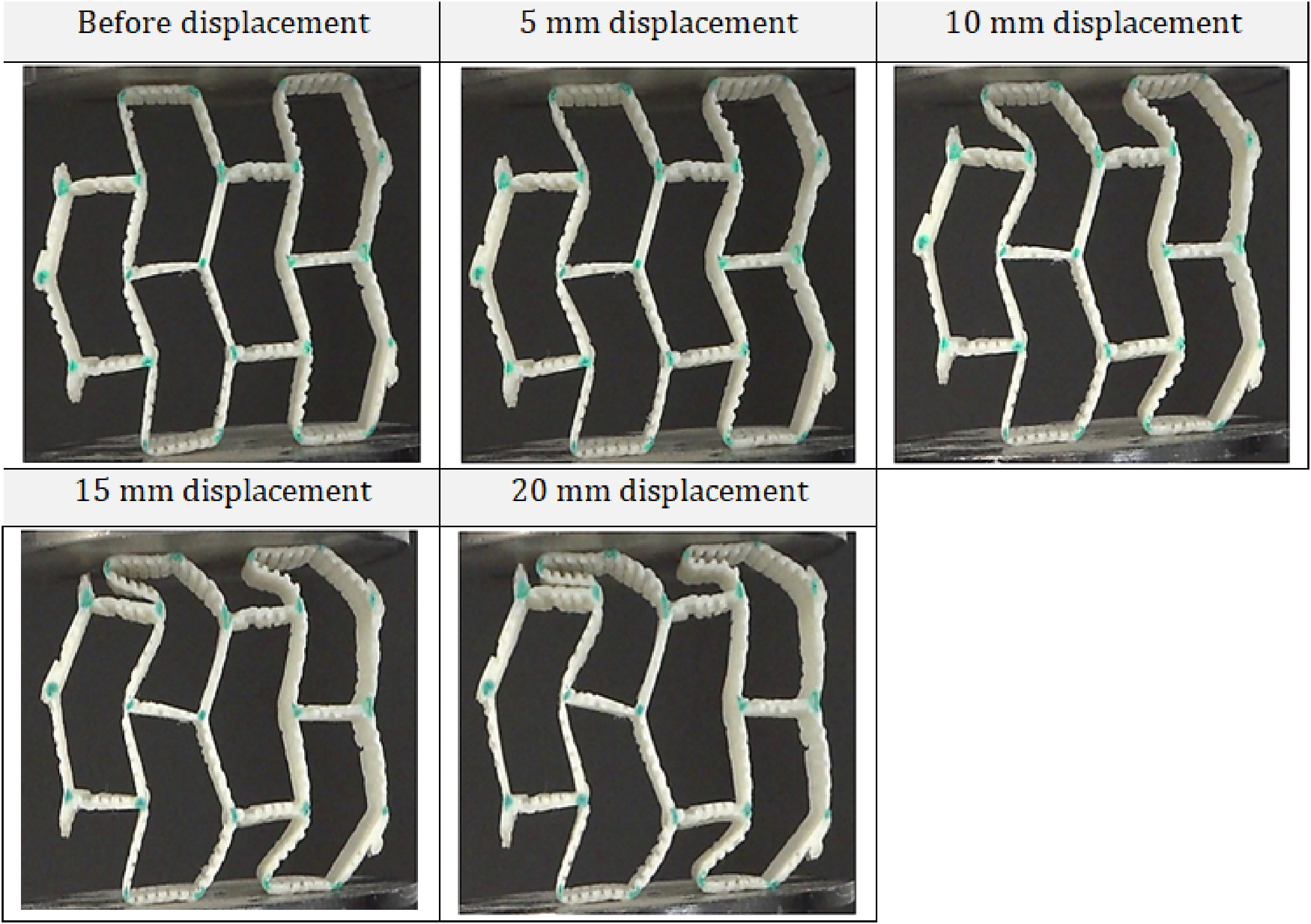
Compressive behavior of spear-head composite structure.
Figure 13 shows the force-displacement curves of three composite structures subjected to compressive loading. These curves denote, initial slope, maximum compressive force and area under the curve. Table 2 shows the features extracted from force-displacement curves.

Exprimental force-displacement represntation of the three composites.
Features extracted from force-displacement curves.

Figure 13 shows that the re-entrant knitted composite initial slope is higher than the other two composite structures. Thus, it can be said that the re-entrant structure is auxetic and has higher resistance against the compressive force. The auxetic feature shown by the re-entrant structure is due to contraction of the 3D structure when subjected to compressive loading. This behaviour is in line with findings of Boakye et al. [1]. The re-entrant composite structure shows linear behaviour up to a displacement of 4 mm and beyond this displacement slope changes due to possible formation of micro-cracks on the resin. Increase in the compression continues till a maximum where applied force decreases. Similar behaviour was observed when the spear-head knitted composite was subjected to compressive force. This was despite of the fact that the initial slope, maximum compressive force and also absorbed energy during deformation of the spear-head knitted composite were much lower than 3D re-entrant composite.
The hexagonal knitted composite showed the lowest initial slope in comparison to the other two composites. This is mainly due to expanding behaviour of this structure under compressive loading condition. In line with re-entrant and spear-head knitted structures, the slope in hexagonal composite was changed after displacement of 4 mm. Increase in the compressive force continues due to engaging the cell walls to each other as well as structural densification.
Poisson’s ratio of the composite structures
Previous studies [30,31], have suggested that theoretical Poisson’s ratio of isotropic 3D re-entrant structure can only be determined by geometrical behaviour. Figure 14 shows the variations of Poisson’s ratio of the three composite structures at different strains. This illustration shows that the hexagonal knitted composites, exhibits the highest Poisson's ratio at relatively low strain and as compressive strain increases, the value Poisson's ratio reduces. From Figure 11, it can be concluded that the high Poisson’s ratio exhibited by this structure is due to rapid buckling of the structure at the beginning of the compression because of oblique walls of the central cell. Further increase in compression necessitates constraining of lateral strain due to densification of the composite structure, as the result of which Poisson’s ratio of the composite structure reduces.
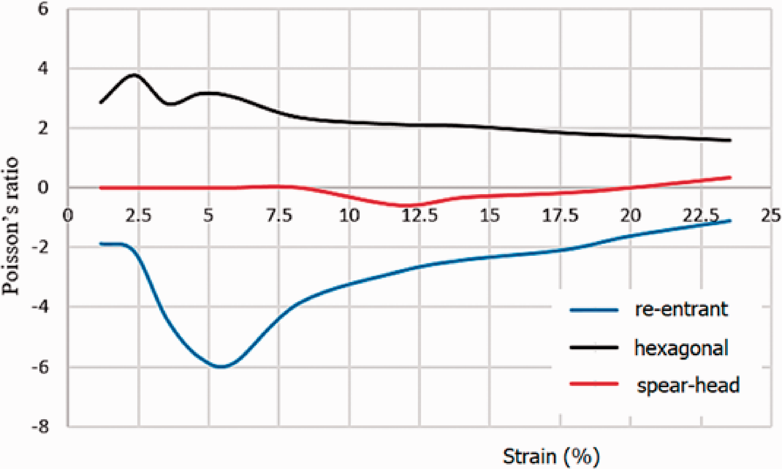
Poisson’s ratio variations at different strains for the three composite samples.
Poisson’s ratio of re-entrant composite structure varies between −6.0 and −1.0. The lowest Poisson’s ratio occurred at strain of 5.4% and beyond strain of 5.4%, the value of Poisson’s ratio tends to increase gradually. The increase in Poisson’s ratio continues till reaching a value of −1.0. The reasons given for Poisson's ratio changes in the hexagonal knitted composites structure could be also applied for this structure.
Poisson’s ratio of spear-head composite structure varies between −0.5 and 0.5. Poisson’s ratio at strain of 8.75% reaches to a value of 0.0 and beyond strain of 8.75%, the Poisson’s ratio value becomes negative; the lowest Poisson’s ratio is achieved at strain of 12.5%. The Poisson’s ratio value changes from negative to positive when the overall strain exceeds 20%, despite of the fact that at this strain level Poisson’s ratio value is still relatively low. Rapid buckling occurs due to oblique walls of central cell at the beginning of the compression loading. This results not only in increase in the lateral strain but also reduces the Poisson’s ratio. According to Figure 12, spear-head composite structure is subjected to limited lateral strain at high strain levels due to gradual closing up of the mid-points of the central cell walls.
Conclusions
Newly-design 3D multi-cell spacer knitted composites with three different cross-sectional geometries were produced on the electronic flat knitting machine and their comressional behavior as well as Poisson’s ratio were evalulated. The re-entrant knitted composite demonstrated the heighest initial slope and area under the force-displacement curve than spear-head or hexagonal composite structures. This indicates that the auxetic composite not only offers higher resistance against the compressive force but also has higher energy absorbing capacity. For re-entrant composite sample, Poisson’s ratio was found to vary between −6.0 and −1.0. The lowest Poisson’s ratio was observed at the strain of 5.4%. Up on strain of 5.4%, the Poisson’s ratio value gradually increased. The observed increase in Poisson’s ratio value continued till value of −1.0. For spear-head composite sample, Poisson’s ratio was found to be varied between −0.5 and 0.5, and at strain of 8.75%, the Poisson’s ratio value reached 0. Up on exceeding strain of 8.75%, the Poisson’s ratio value changed to a negative value. The Poisson's ratio value changed from negative to positive, when strain exceeded 20%. As far as hexagonal knitted composites is concerned, it was found that at relatively low strain, this composite sample has the highest Poisson's ratio. It was concluded that with increase in compressive strain, the Poisson's ratio value of the sample decreases and varies between 4.0 and 1.6. The developed 3D knitted composites could be used as core materials for sandwich panels. Mechanical properties of the sandwich panel will be different according to the poison ratio of the core structure.
Footnotes
Declaration of conflicting interests
The author(s) declared no potential conflicts of interest with respect to the research, author-ship, and/or publication of this article.
Funding
The author(s) received no financial support for the research, authorship, and/or publication of this article.