
Abstract
The textiles capable of cutting resistance found applications in the industrial and military areas to construct flexible lightweight soft body armors. In the present work, a theoretical model to understand the mechanism of fabric cut resistance in a different direction for weft-knitted, triaxial, and multiple layers structures. An experimental study of cutting resistance force was done on weft-knitted fabric with Kevlar 29 triaxial fabrics in multiple layers structure to support derived mathematical model for the effect of multiple layers structure on their cutting force. The study examines specific cut resistance of the structure from four layers of Kevlar triaxial fabrics covered with knitted fabric on both sides. The angle of cutting force varied from 0°, 60°, and 90° with respect to the yarn inclination. Results show that the cutting force of the multilayer structure is linearly proportional to the number of Kevlar triaxial fabrics layers. The specific cut resistance value of the structure from four layers of Kevlar triaxial fabrics, covered with knitted fabric on both sides, reached 544, 435, and 326 (N/g/cm2) for cutting directions: angled 60°, vertical, and horizontal, respectively. In this work, the comparison between the triaxial fabric of high areal density and multiple layers of triaxial fabric with resultant same areal density indicates that a better specific cutting force was achieved in the first case. Furthermore, it investigated the relationship between triaxial surface density, the direction of cutting, and the number of triaxial fabric layers and discussed the optimum specific properties of the different structures.
Introduction
Some protective fabrics may be subjected to various forms of cutting, slashing or stabbing. This is the case of industrial gloves that can be pierced by sharp tools or body protective armour fabrics [1–3] that can be stabbed during terrorist assaults. Many other applications, such as military, security, and industrial applications require protective clothing exhibiting high cut or slash resistance. Therefore, it is recommended to enhance the protective fabrics’ properties with a substantially high blade cut resistance. Commonly, knitted fabrics are utilized as protective fabrics in several applications and as protective armours for soldiers and law enforced personnel. The protective fabric may be subjected to cutting, slashing, stabbing, combined puncture, and cutting. In each case, the mechanism of cutting of the fabric is different [4]. The relative motion of the blade and fabric is typically characterized by the direction of cut and the velocity of the blade, the punching load stabbing energy, the interaction between the fabric and the blade sharpness, and the properties of the fabric material and structure. The scenarios of the penetration mechanism into a textile material represent cutting with a sharp blade, stabbing with a knife or spike, and slashing with a sharp blade (knife) at a high speed [5–7]. Each case has the fabric resistance force for blade penetration, and it relies on the blade sharpness, the blade speed of penetration, and the construction of a punched textile. It was revealed that the reduction in cutting force due to a slicing motion is only prevalent in the cut initiation and does not play a factor when the crack is already formed. Stab threats can be punching or cutting. Knife threats are, generally, more problematic to stop than punching ones due to the knife cutting edge continuous damage that was initiated after the stab. Consequently, for stab protective armor the different materials are used with high tenacity, tear, and cutting stress besides stiffness and shear. The stabbing mechanics of the combined puncture and cutting of protective materials by a pointed blade have been studied theoretically and experimentally [8–12].
The slash resistance of the fabric is the maximum cutting force when the cutting tool is attacking the fabric tangentially to its surface with the impact force. It was revealed that the overarm stabbing speed is 10 m/s, depending on a method of stabbing and the relative speed between walk-on and stab speeds. The peak punching force can reach a value of 1990 – 4740 N [13,14]. With the requirements of the lightweight and comfortable cut-proof clothes, the knitted fabric has the advantages of its structure and is more and more widely used. The cut resistant mechanism of fabrics is much more complex due to their fiber and yarn intrinsic properties and fabric structure [4,15]. 3 D fabrics, knitted on a circular weft-knitting machine, ensure 1.3–2.1 times greater blade cut and 4.9–12.1 times greater abrasion resistance than the fabrics of the same composition that are knitted on a circular weft-knitting machine. This is due to a higher stitch density, higher mass per unit area, density, and thickness [16]. The yarns used may be pure high-performance fibers, special organic fibers such as para aramids, high molecular weight polyethylene (HMWPE), and inorganic fibers like S2 glass for better effect on the material cut resistance behavior [17–19]. The multiple layers of knitted fabrics from the different materials and structures were studied by several researchers [20–21]. The slash test was conducted in three different directions, and they are referenced in the discussion as shown below: wale-wise, course-wise and slash crosswise at 30° to the wale-wise direction. The results show that the fabrics had better resistance to slashes or cuts in the course-wise direction and the crosswise direction [22]. The resistance in the wale-wise direction was low. The test blade tends to slip in between the two adjacent wales or columns of the loops in the wale-wise direction and cuts through the fabric fairly easily. The single jersey structure exhibited the highest resistance to the slash in the course-wise direction, but it failed badly in the wale-wise direction and failed marginally in the diagonal direction [23]. Cut resistant mechanism of weft knitting structure is much more complex. There is still a lot of work to continue to get a thorough understanding of the mechanism of fabric’s cut resistance due to it is contributed by several parameters [24,25]. Continuous efforts to provide a fabric displaying high blade cut resistance have so far resulted in fabrics that are significantly heavier, less flexible, and thereby less comfortable to wear [17]. For protective armour, many different materials, fabric structures, and armour designs have been suggested to provide cutting resistance, comfort for the user, a lightweight, and cost-effectiveness [4]. The objective of the present work is to drive the formulas for the cutting resistance of weft knitting and triaxial fabrics in the multiple layers structures and to find out the parameters of the knitted fabric to exhibit higher blade cut resistance. Experimental measurements of the factors affecting the cutting resistance were investigated.
Materials and methods
Materials
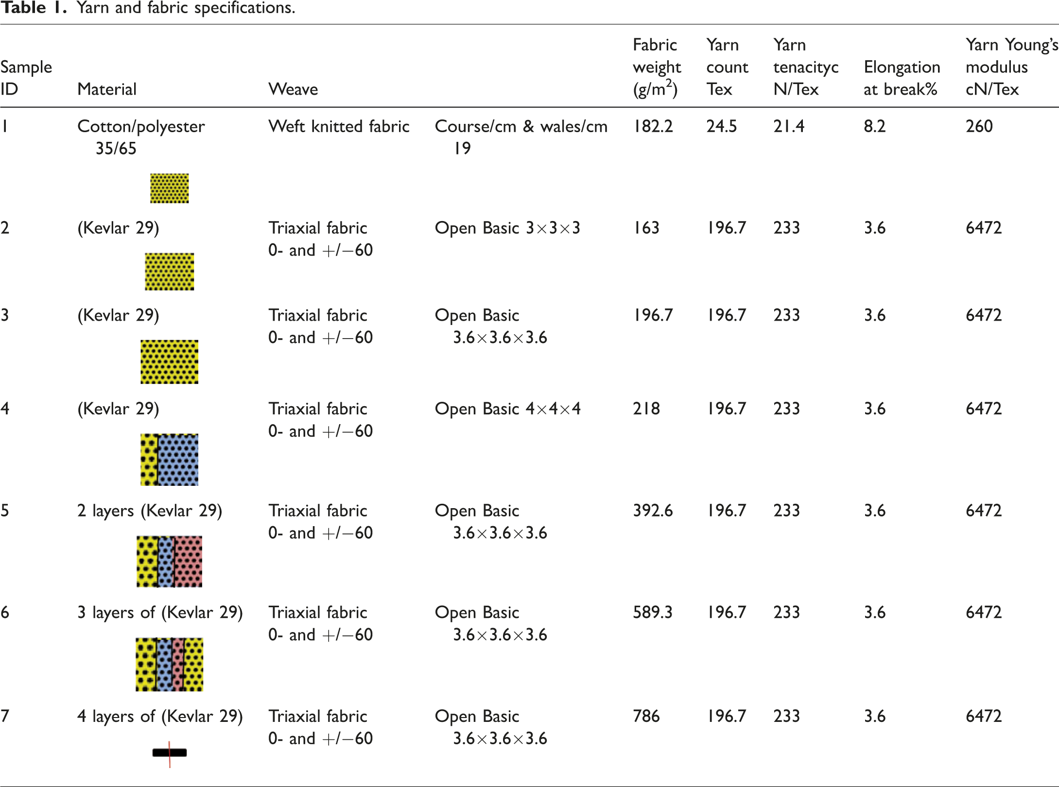
Samples of weft knitted fabric and triaxil fabrics (TWF), with the arrangements of the yarns interlacing in these fabrics at the angles of 0, 60° and −60° so that the stiffness and strength are similar in every direction as well as the bending stiffness (quasi isotropic), were prepared. Different specifications of the triaxial fabrics samples from Para-aramid® 29 (Kevlar 29) yarns are given in Table 1.
Yarn and fabric specifications.
Cut resistance testing setup
A rectangular fabric test sample is placed outside the plastic cylinder mandrel of diameter 50 mm and clamped tight with an appropriate force to hold the sample in place but not to cause any residual stresses within the area to be cut, which is a groove on the top surface of the fabric holder with a length of 25 mm and width 3 mm [26]. The blade’s angle can be set before starting the test of the cutting process. The cylindrical mandrel sample holder is firmly fixed on the table and pressed to the blade holder by the predetermined load. Figure 1(a) and (b) gives a photo of the developed setup.

Testing device for the measurement of fabric cutting resistance. (a) Real photograph of testing set-up (b) schematic of fabric cutting mechanisms.
The fabric, mounted in the test machine and clamped with the sample holder on sides, is forced against the moving blade. This can be seen in the photographic representation shown in Figure 1(b).
Testing procedure
Required samples for cutting resistance testing in wales and course directions are taken from various locations throughout the knitted fabric. For each fabric, five samples 157 × 100 mm in the wales-wise and course-wise and at 30° to wales-wise directions were prepared. The critical normal load was firstly determined before carrying out the test in each case that required to cut all the yarns in a length 25 mm (Ncritical). The blade sharpness and the slicing angle were fixed for all the tests; a new blade was used for the same sharpness and perpendicular to the cutting direction. The testing speed was set to 275 mm/min for knitted fabric and 660 mm/min for Kevlar-29 triaxial fabric. The mounted fabric was stretched tight on the fabric holder. The cutting force of the five samples was tested in the above-mentioned directions. Laboratory samples for acceptance testing are taken at a random from each fabric type, and the average and standard deviation of the cutting force and other mechanical properties were calculated in each direction [ASTM F1790/F1790M – 15].
The test was performed on all five fabric samples for each testing condition. During the test, the vertical edges of the specimen are aligned parallel to the face of the slot in the specimen holder in the first test, perpendicular in the second test, and at an angle of 30° to the long axis of the slot in the specimen holder in the third set; each sample was tested in the walewise (0°), coursewise (90°), and bias (30°) directions [22].
Geometrical model of weft-knitted loops
In weft knitted fabrics, the yarns take the form of loops, created by drawing the yarn through the loop from the previous row. Figure 1 shows a simplified 2 D loop geometry plane view of weft knitting loop construction used in the analysis of cutting force possibility. The cutting force, influenced by the direction of slicing, as illustrated in Figure 1, will vary according to the cut yarns. The blade may cut only the yarns of a single loop or the other parts of the neighboring loops. Assuming that the blade has a length of (L), then the cutting force will depend on the direction of the cut. The loop height (H) is the unit that represents the cutting processes of the knit unit, then a blade will be resisted by one loop if the loop’s length (L) is equal to (H). Based on the “stitch geometry” of weft knitted fabric architectures, the possible cutting direction of the loop by a blade of length (L) is shown in Figure 2. The number of full cuts (m) with the neighbor raw of courses of the fabric depends on the length of the blade as well as the number of wales and courses.


An illustration of the geometrical parameters to define the architecture of knitted textiles: course spacing (P), wale spacing (W), loop height (H).
To calculate the value of the cutting force in the different directions as shown in Figure 3, one loop is considered. Circles 1, 2, 3, 4, 5, and 6 represent the interaction between the course and wale loop circle and a blade length. In the case of interaction of the circles 1, 2, and 3 with the circles 4, 5, and 6, the blade of length (H) will cut the neighboring loops too. Hence, the choice of (H), (p), and (W) affects the total cutting force of the knitted fabric under a blade of length (L).

Interaction of the loop circle with the neighbor loops.
Knitted fabric have the heterogeneous distribution of the material in a different direction [13], then cutting forces will differ according to the direction of the blade inclination. Usually, the cutting test of the knitted fabrics is done in the wales and courses direction as well as angled at 30° to the wale’s direction, i.e. in positions 1, 3, and 5 [22]. The cutting of one loop was analyzed, Figure 4, and the following equations of the values of the cutting forces were derived:


Different possible cutting directions of the loop.
where: d is the yarn diameter, τ(0) is shear stress when the blade is perpendicular to the yarn cross-section, τ(90) is shear stress when the blade cuts along to the yarn axis, L is the leg of the loop, p is course spacing, W is wale spacing, α is the inclination of the loop leg to the y-axis.

The value of the number of neighboring loops cut by the blade (m) should be multiplied by the value of the cutting force of each loop, calculated by equations (1) to (3). From the analysis of the above equations, it is clear that the value of the cutting force of the knitted fabric varied from one cut position to the other. The maximum cutting force is FC3 when the cut passes the yarn body at the loop leg and minimum when the cutting direction passes through the axis of the loop. In all cases, the value of the cutting force is elevated when using large yarn diameter from fibers of high cutting stress, as well as the choice of the fabric structure with a high density (wales per cm × courses per cm) and (H/W) ratio. The cutting force (FC3) is expected to be the highest and (FC5) is the lowest. The above-driven equations can be applied to calculate the cutting resistance of the weft knitting fabrics in different directions of cut. The knitted fabric could achieve the flexibility required for the armour design.
Multiple layers structure for protective armour
Body armour has the purpose of protecting the upper torso, particularly in the military and police sectors. Some designs of lightweight body armour were adapted to the manufacture of the female body armour due to the needed curvature in the armour contour that could affect the protective and comfort performance [27]. For protective fabric, the applications of multiple layers of knitted fabrics have been used [28]. Also, the knitted structures were developed for cut and puncture protection from several layers of different fabrics: Structure 1– Single jersey; Structure 2 – Crepe; Structure 3 – Moss Tuck Stitch [29]. When designing a soft armour, multiple layers parameters should be taken into consideration, for instance, movement disorder and lightweight with a good customized fit is especially important for the female wearer [4]. In order to improve the cut resistance force value, in this study, it was suggested to construct a multiple layers architect consisted of two layers of weft knitting fabric laid over a triaxial fabric on both sides. The triaxial fabric has the ability to accept 3 D curvature without deformation of the weave or wrinkling. This is due to its low shear modulus besides a high air permeability comparing to the other fabric designs. The upper and lower layers of the multiple layers structure can be chosen from the weft-knitted fabric of cotton or cotton/polyester yarns to increase the structured comfort. In this study, the specifications of the knitted fabric were chosen in the way that the leg of the loop has 30° to the wale direction and can lay exactly on one of the triaxial yarns [22].
In this case, the cutting force will be higher due to the presence of the second layer of triaxial fabric made from high-performance fibers (Kevlar 29). The high-performance fibers have high tensile strength, modulus, and cutting resistance [4,19,26]. However, they are not recommended to be directly in contact with the skin for the comfort aspects [4], thus the use of cotton or cotton blend knitted fabrics will help in this context. To maximize the cutting force, the parameters of both fabrics in the multilayer structure should be chosen according to that the yarns in the triaxial fabric have the same angle of the leg of the loop as in the knitted fabric. Figure 5(a).shows the top view of the unit loop architecture of weft knitting. The loop height (H) is

(a, b) Illustration of the cutting direction of loop of knitted and triaxial fabric unit.
where: tan(α) = [(0.5W + d)/2p], r = (0.5 W + 0.5 d)(1 + (d/p)2) 0.5
Then
In this analysis, an architect of the triaxial fabric was considered, as given in Figure 5(a), with a possible arrangement to increase the cutting resistance in the directions 1, 3, and 5 of such multiple layers structure.
Analysis of the geometrical parameters of multiple layers structure from weft knitting weave and triaxial fabrics
The cutting force of the knitted fabric usually is measured in three directions: wale-wise, course-wise, and at angle α = 30° to the wale-wise direction [22]. Therefore, it was necessary to design the weft-knitted fabric having the loop leg angled at 30° to the wale-wise direction, as shown in Figure 5.
Theoretical model
In the multiple layers arrangement, one of the yarns of the triaxial fabric is laid in the horizontal direction, while both yarns are inclined to it at an angle 90 - α so that the cut resistance at that inclined direction (3) will increase. The value of the angle α depends on the parameters of the knitted fabric. At the same time, it is required to have an equal pitch between the different yarns of the triaxial structure, i.e. α = 30°, a = b = 0.5p. A computer program was used to find the knitted fabric specifications that satisfy that condition for different values of yarn diameter, i.e. wales/cm and course/cm, assuming α = 30°. Figure 5(b) shows the structure parameters of the triaxial fabric. The cutting direction of the loop of the knitted architecture unit laid on the triaxial structure fabric is shown in Figure 5(b). where: wales spacing (W), the blade length (L), L = H, and W < H, then
The specifications of the knitted fabric, targeted to have a loop leg angled exactly on the triaxial yarn, as shown in Figure 5(a), are varied according to the yarn diameter. Table 2 gives the theoretical values of the knitted fabric specifications for the different yarn counts with the intention that the yarns of the triaxial fabric lay on the loop leg. The relationship between the dimensionless parameters of the weft-knitted fabric as Kc (Course constant = Course per cm×loop length in cm), Kw (Wales constant = Wales per cm×loop length in cm), S (Stitch density = Course per cm×Wales per cm), Ks (Stitch density constant = S×(loop length in cm)2), and Loop shape factor (Kc/Kw) were calculated [24] to have the following conditions: a = b = 0.5p and the angle of inclination of the loop leg equal to α = 30° for the different values of the yarn diameter, in this analysis W = 4d [30,31].
Analysis of geometrical parameters of weft knit weave for different yarn diameters.

aThe cover factor is the ratio of the area covered by the yarns to the fabric total area.
Table 2 illustrates that both wales and courses per cm decrease as the yarn diameter increases, keeping the value of the angle α = 30° to the wales direction. Because of the change in the number of the wales and courses per cm, the stitch density will vary, and the fabric tightness will change exponentially. Fabric weight per square meter is found to increase for the coarse yarns. The limiting factor that determines the count of the yarn for weft knitting (Tex) in these cases is machine gauge. Based on the experience, some guidelines have been established for selecting the count of yarn (Tex) to be knitted on a knitting machine of a certain gauge and are given by Tex =1650/G2, where (G) is the machine gauge [31]. The diameter of the yarns (DTA), used for the triaxial fabric, must be greater than the diameter of the yarns used for knitted fabric, i.e. DTA > d.
In all cases, the relation between the yarn diameter, forming the triaxial fabric and knitted fabric, and d and W is
Analysis of cutting force of multiple layers of fabric
Most of the hand injuries occur because of slicing or stabbing of the protective fabric by a sharp-edged blade. In this situation, the cut resistance of the fabric has a pronounced effect to protect the wearer [4].
The theoretical model of multiple layers structure
The multiple layers structure consists of layers of weft knitted fabric and triaxial fabric from high‐performance yarns (Kevlar 29). The cutting force of the multiple layers structure will be different depending on the direction of the blade movement to cut the knitted fabric and the triaxial fabric altogether. The total cutting force will be the sum of both cutting forces. The direction of the cut of the multiple layers structure is: Horizontal cut (FCM1), Angled cut (FCM3), and Vertical cut (FCM5). The following are the expected values of the cutting forces in the three directions


where: d is the yarn diameter, τ(0) is shear stress when the blade is perpendicular to the yarn cross-section, τ(90) is shear stress when the blade cuts along the yarn axis, τ(0)1 is shear stress when the blade is perpendicular to the triaxial yarn cross-section, τ(90)1 is shear stress when the blade cuts along the triaxial fabric’s yarn axis, L1 is the leg of the loop, C is course spacing, W is wale spacing, α is the inclination of the loop leg to the y-axis, L = (p2 + d2)0.5, L1 = (((0.5 W + d)/2)2 + p2))0.5. From the analysis of the cut forces in such a model, it can be revealed that the value of (FCM3) is the highest. However, the total value of cutting force in any direction depends on the value of (m) in equations (1), or (2), or (3).
Results and discussions
Mechanism of fabric cutting
The analyses of the cutting mechanism indicated that during the cutting processes the yarns in contact with the blade will be deflected under the normal force applied on the blade. Then the blade starts to penetrate through the fibers in its path with the increasing stress till the cross-section of all the fibers is reduced to the limit and the residual fibers fail under the tension stress. The yarn failure has several stages: 1- shearing of the material by the sharp edge of the blade; 2 - shear–tension; and 3 - strain failure. The total energy required to penetrate EF significantly relies on the cutting energy to cut all the fibers in the yarns by the edge of the blade. It consists of several components: yarns material cutting energy EYc, yarn strain energy to deform all fibers due to the normal force applied by the blade EYs, energy to overcome the friction between blade and yarns EYf, and energy to move the blade during cutting EFd.
Yarns material cutting energy depends on the fiber material cutting force and the structure of the yarn (spun yarn, mono-filament, or multi-filament). The yarn cutting resistance surges as the blade penetrates through the yarn axis until it passes through it, then the cutting force drops until cutting all the gripped fibers under shear and strain forces. The yarn strain energy is a function of the tensile properties of the yarn and the fabric structural parameters. The normal force applied to the blade plays a significant role in the determination of the cutting resistance. The reduction in cutting force is due to the fact, that it takes a fixed amount of energy to cause crack propagation and that adding slicing motion reduces the amount of push energy required to cut [4,5]. Hence the blades usually are very thin and smooth, the two energies EYf and EFd can be neglected. In the case of the continuous multifilament yarns, when the blade moves along the yarn axis, the resistance is less than when the blade’s movement is perpendicular to its axis, therefore the blade may split the yarn filaments and pass between, not cutting anyone, and the two energies EYc and EYs exhibit the higher values. In the spun yarns that have most of the fibers twisted and inclined at a certain twist angle to the yarn axis and with the twist angle varied across the yarn cross-section, a fiber at the yarn center is parallel to the yarn axis and inclined to it at its different layers. At the surface, the fiber is inclined to the yarn axis by an angle equal to the twist angle. In his case, the blade will have to cut the fibers with a different cutting angle. In contrast, in the case of multifilament yarns, all of the fibers are parallel to its axis [25]. Table 3 gives the values of the cutting force for the different cutting situations for yarns arrangement of the Kevlar 29 and cotton/polyester yarns.
Cutting force for the different cutting situations for yarns arrangement of the Kevlar 29 and cotton/polyester yarns.

aCV%.
Figure 6 indicates that the single Kevlar 29 yarn cutting force reaches 1.37 N at a vertical load of 2.54 N, while the cutting force for two crossed yarns and inclined 60° degrees on each other needs a little higher normal load to start cutting, and the cutting force will increase up to 2.18 N. This is because the yarns are not a monofilament, and the cutting of one filament will increase the tension on the rest of the filaments in the cross-section, resulting in the reduction of the final cutting force. When there are three crossings and one longitudinal cut, the tension on the crossed yarns during cutting reduces and adds a small force due to friction between the blade and fibers throughout its movement. The cutting force reaches 3.1 N and a higher normal force is required. From this analysis, it is clear that the cutting force of the triaxial fabric will be affected by the direction of cutting.
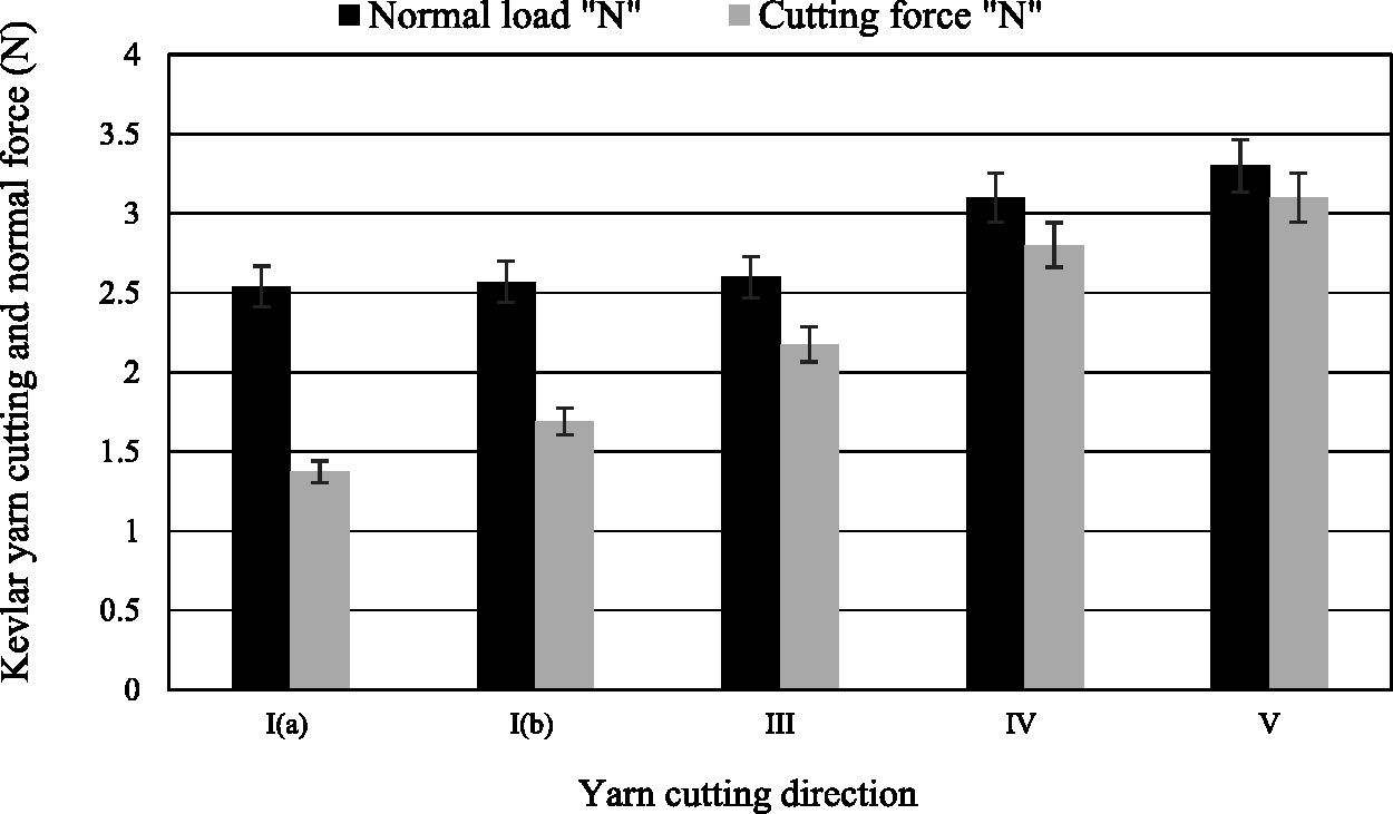
Cut and normal forces for different cutting directions of Kevlar 29 yarn (Table 3).
Fabric cutting resistance
For the suggested multiple layers structure, knitting fabric for the upper and lower layers provides the wearer’s comfort for the flexible armour [4]. While the triaxial Kevlar 29 fabric is mainly used to assure the required cut resistance force of the armour to satisfy the standard.
Cutting force of the knitted fabric
The knitted fabric was tested in the following three directions: wale-wise direction (vertical direction), course-wise direction (horizontal direction), and 30° diagonals to the wale-wise direction (loop leg direction). The cutting force-displacement curves are given in Figure 7. The blade’s movement passing through the fixed sample starts with the cut of the yarns section at the entry point. The resistance increased as more yarns resist the movement of the blade till the peak transverse cutting force. At the late stage of the test, the blade will start to leave the cutting area, and the cutting force will be gradually reduced. The area under the cutting force-displacement curve is the energy absorbed in deforming and then breaking the yarn. The shape of the cutting force-displacement curve shows that a large fraction of the cut energy is absorbed after initial yarn breakage. The cutting direction 30° shows the highest value.
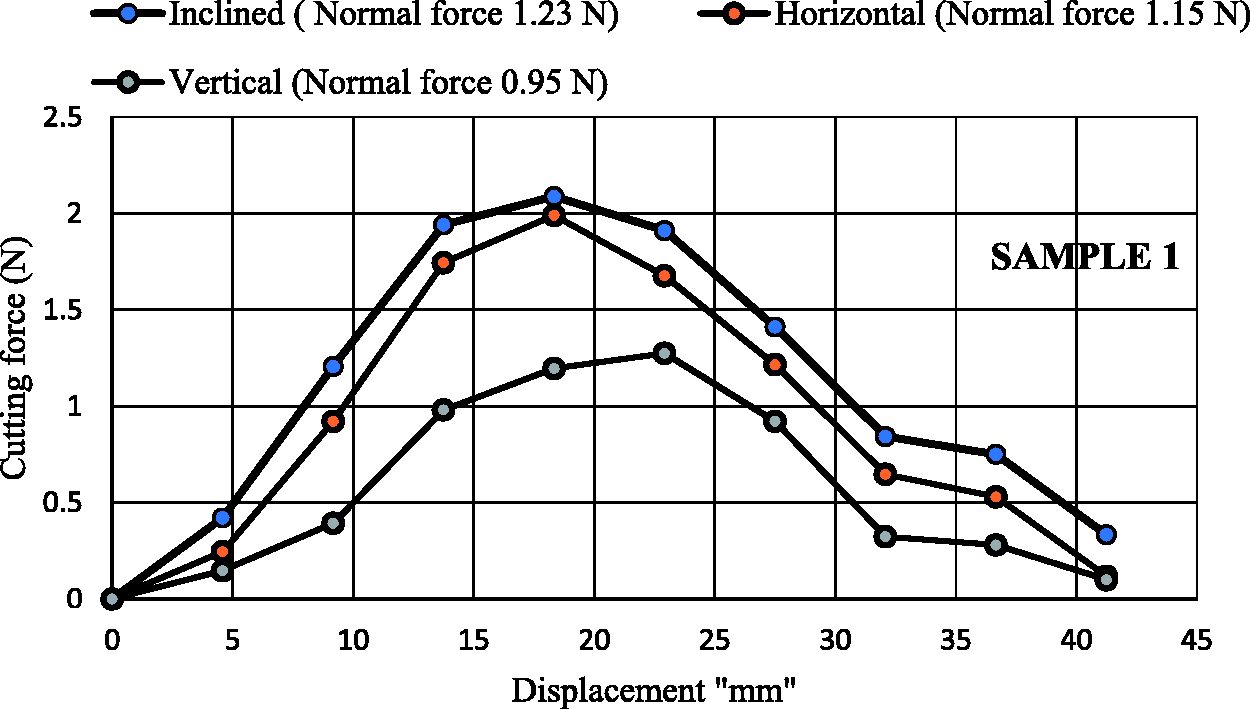
Knitted fabric’s cutting force-displacement curves for different directions of cut.
Figure 8 indicates that the highest value of the cutting force reaches 2.1 N at a normal force of 1.23 N. The results demonstrated that knitted fabric was deformed, stretched, and cut during blade cutting. The failure occurs by breaking of yarns by cutting and straining under the tension due to the normal load [8,32].

Knitted fabric’s cutting force and normal force for different directions of cut.
The cutting energy of the knitted fabric is highest in the case of the angled cut, as shown in Figure 9.

Knitted fabric’s cutting energy for different directions of cut.
Cutting force of kevlar 29 triaxial fabric
Triaxial fabrics are unique structures that have wide application in multiple layers of industrial applications [33–35]. Triaxial fabrics are defined as cloth in which there are three sets of threads from a multitude of equilateral triangles, thus forming a more stable construction because triangles are more stable than loops of a knitted fabric. Basic triaxial fabric is fairly open, with a diamond-shaped center. The arrangement of the yarns interlacing in these fabrics is at angles of 0, 60°, and –60° so that the stiffness and strength are similar in every direction, as well as the yarns have no interlacement [36]. This structure will allow the three yarns to participate easily in the resistance of the applied load on the blade and resist the blade movement during yarns cut [5,26]. The fabric was tested in the following three directions: vertical direction cut, horizontal direction cut, an angled cut 30° to the vertical axis. The cutting force-displacement curves are given in Figure 10. The cutting force and normal force on triaxial weave for different cutting directions are shown in Figure 11.

Cutting force-displacement curves on Kevlar triaxial weave in vertical, horizontal, and inclined 60° directions.
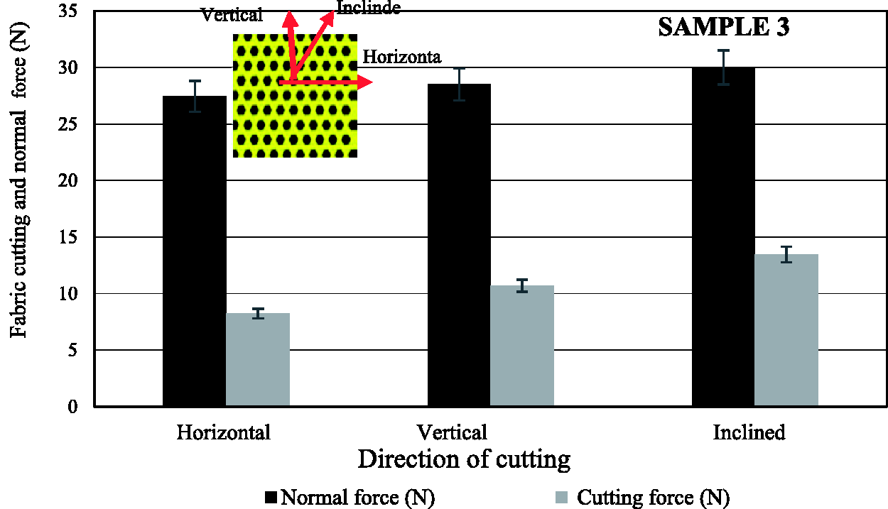
Triaxial fabric cutting force and normal force for different cutting directions.
Table 4 shows a comparison of the cutting force and normal force for knitted and triaxial fabrics. The cutting direction No. V (three yarns 60° on each crosscut + one longitudinal cut (Table 3) had the highest value, it reached 13.5 N at a high value of the normal force of 30 N.
Cutting force and normal force for knitted and triaxial fabrics.


aCV%.
The cutting energy of the yarns in different directions, as given in Table 4, also varied according to the number of the cut cross-section as well as the applied tension on the yarns.
Figure 12 shows the cutting energy, which indicates that the highest value of cutting energy occurs with the angled cut, hence 4 yarns are cut. The use of triaxial fabric gives a higher specific cutting force than in the case of use Kevlar 29 yarns in knitting structure [23].

Triaxial fabric cutting energy for different cutting directions.
Cutting force of multiple layers structure
The currently available stab-resistant armours are very rigid to be worn comfortably and are heavy for everyday use by the civilian population. For comfort purposes, the armour should be flexible and allow heat convection through the structure of its layers, so it can be utilized for long periods [4]. The reinforcing performance of multiple layers structure was comprehensively studied, in this work we suggest forming the armour from knitted fabric at the outer layers and having a triaxial Kevlar 29 fabric layers in between. Different designs of multiple layers structures were tested to find out the number of triaxial Kevlar layers to pass the specifications required for the end-user. Samples were tested for cutting resistance in the following three directions: vertical direction, horizontal direction, and 30° inclined to the vertical direction [37]. Figure 13 illustrates the effect of the multiple layers structures consisted of the knitted fabric layers and one layer of the triaxial Kevlar 29 fabric tested in the angled cut direction compared to their cutting force. The structure of knitted fabric on the upper and lower surfaces with one layer of Kevlar 29 triaxial fabric showed the highest value. The cutting energy of 2 knitted/triaxial fabrics combination increased significantly, as given in Figure 14.

Cutting force of different samples (knitted/triaxial, Kevlar, and knitted fabrics).

Cutting energy of different structures of Kevlar and knitted fabrics and the multi-layer structure.
The extensibility of the knitted fabric under normal load is higher than that of triaxial fabric under the same normal load. During cutting, the blade can either completely or partially pierce through or can be entirely halted by the triaxial fabric, hence the more yarns in the triaxial fabric will resist the movement of the blade because of the low shear modulus of the triaxial fabric. Consequently, more cutting energy is required to complete the cut through the different layers of the multiple layers structure. The multiple layers fabric requires more cut energy based on the following mechanisms: fabric shear; fiber and yarn extension; fiber rupture by cut, which differentiate through the layers as well as the friction between the layers during fabric deformation [4,8,37].
To increase the cutting force of soft armour, several layers of triaxial fabric were suggested. Four samples were prepared to find the relationship between the number of Kevlar 29 layers, and the cutting force was measured. Figure 15 shows the association between the number of Kevlar 29 triaxial layers and angled cutting force. The cut resistance increases with the increased layers of triaxial fabric in the structure. For all samples, the upper and lower layers were knitted fabric. A sample of 4 Kevlar layers exhibited the highest cutting force with 63 N and the CV% of 2.48.
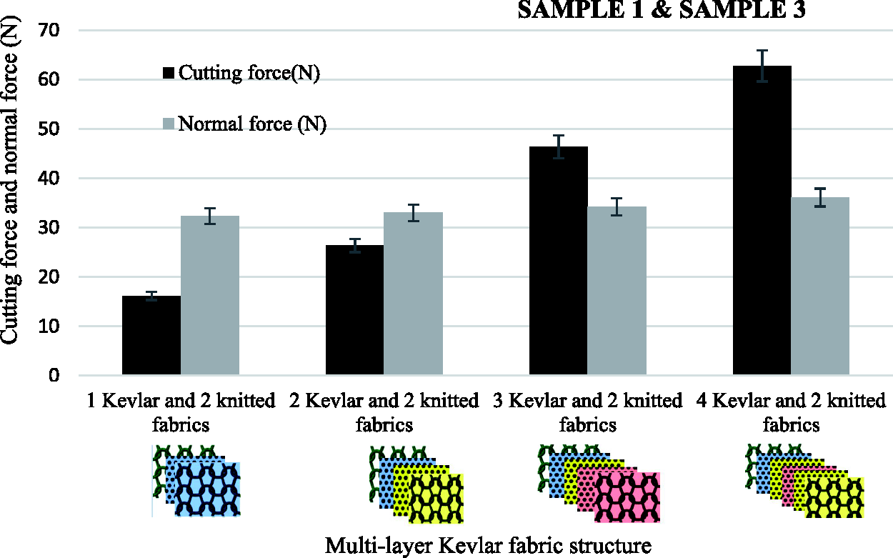
Cutting and normal force for different number of Kevlar triaxial layers in the multi-layer structures.
The specific cutting force is a key factor of the armour weight thus, it was calculated by dividing the maximum load by the areal density of the sample. Apparently, this increase in the areal density (GSM) supports the ability of the fabrics to stop cutting at a particular normal force. Figure 16 shows the specific cutting force versus the number of triaxial fabric layers for the different cutting directions. The increase in the number of layers means that more yarns need to be cut to allow the movement of the blade, therefore resulting in the elevating of the specific cutting force [25]. However, the triaxial fabric has no yarn interlacement. Consequently, during the movement of the blade, the yarns will slip over each other and give an extra blade movement resistance, and higher cutting resistance force was recorded. The specific cutting energy reveals the same trend, as shown in Figure 16(a). Both, the specific cutting force and cutting energy, increases as the number of the Kevlar 29 layers increased [4,8,32].
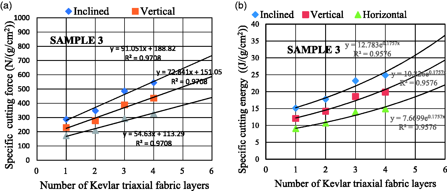
Specific cutting force and energy versus number of Kevlar triaxial layers. (a) Specific cutting force and (b) specific cutting energy.
Specific cutting force (b) Specific cutting energy
Advanced body armour technologies aim to reduce the vest weight in order to enhance comfort level [38,39]. It is reported that users are reluctant to wear uncomfortable protective vests because they are heavy and inflexible [40]. This requires determining the exact number of layers of the triaxial fabric, with the specific cutting resistance satisfying the standards, and can be calculated by the linear fitting, and the final regression equation is as follows
where: Nl is the number of the triaxial layers
From Figure 16(b), it was noticed that the specific cutting energy increases exponentially with the increase in the number of layers of Kevlar fabric, this may be due to that the increase of the friction between the fabric layers and shear rigidity of the fabric increases the resistance energy required to move the blade through the multiple layers structure [4,8]. The specific cutting energy can be calculated by the exponential fitting, and the final regression equation is as follows
Figure 17 shows the specific cutting force of the samples with one triaxial fabric layer of different areal density covered by cotton/polyester knitted fabric on both sides.

Specific cutting force versus areal density of one layer Kevlar triaxial fabric.
It was revealed that a better specific cutting force was achieved when using triaxial fabric with higher areal density than multiple layers triaxial fabric with resultant same areal density. However, the flexibility of fabric was noticeably reduced, which in turn, may reduce the mobility of the wearer [41].
Conclusion
In this study, it was proved that it is possible to manufacture multiple layers structures with better cut resistance performance by the optimization of the weft knitting fabric and the triaxial fabric layout within the multiple layers structure. The theoretically derived equations illustrate the effect of a multiple layers structure on the cutting force in horizontal, vertical, and 60° directions. Also, they allow calculating the cutting resistance of weft knitting fabric, triaxial fabric as well as of a multiple layers structure.
The experimental data comes to validate the theoretical model with the following findings:
And here: The angled cutting force of Kevlar fabric reaches 13.5 (CV 4.43%) at normal load 30 N. The specific cutting energy of the structure consisted of four layers of Kevlar triaxial fabric covered by a layer of knitted fabric with particular parameters from both sides, reached 24.8 (J/(g/cm2)) and the specific cutting force reached 545 N/(g/cm2) in an inclined direction. The cut resistance increases linearly with the increase in the number of layers of triaxial fabrics. The structure consisting of 4 Kevlar layers exhibited the highest cutting force with 63 N and the CV% of 2.48. Better specific cutting force is achieved when using triaxial fabric with higher areal density than multiple layers triaxial fabric of the resultant same GSM. The number of layers depends on the required level of cutting force. The structure of (cotton-polyester) knitted/triaxial Kevlar 29 multiple layers fabrics is considered to possess a high potential for the formation of flexible slash-resistant armour.
Footnotes
Declaration of conflicting interests
The author(s) declared no potential conflicts of interest with respect to the research, authorship, and/or publication of this article.
Funding
The author(s) received no financial support for the research, authorship, and/or publication of this article.