
Abstract
This study presents the experimental characterization and finite element investigation of a piezoelectric nanogenerator based on electrospun poly(vinylidene difluoride) (PVDF) nanofibers walking energy harvesting applications. The piezoelectric response of nanogenerator device was experimentally evaluated under low frequency cyclic impacts using PiezoTester. The impact test was then simulated and the obtained experimental applied force-time curve is implemented into the finite element model as the impactor external force. Based on mentioned procedure, a novel iterative finite element simulation was then introduced to determine the piezoelectric properties of PVDF nanofibers to avoid any redundant experiments. The experimental voltage-time was compared with voltage time obtained from optimized finite element model and a reasonable agreement was achieved between the numerical and experimental curves. Thereinafter, as a case study, a PVDF nanofibers nanogenerator integrated foam (PNIF) was simulated to use as an energy harvester in the shoe insole. The validated finite element model was then constructed to optimize the PNIF elasticity modulus to reach the maximum efficiency of energy harvester during human walking. The results showed that the best efficiency of the energy harvesting is achieved for 211.27 kPa PNIF modulus, which can generate 15.1 V. These results lead to the establishment of engineering design rules in the industrial scale for wearable power harvesting devices in the footwear industry.
Keywords
Introduction
In the recent years, there has been an extensive attention toward the energy harvesting from mechanical body motions as a promising way to power portable and wearable devices [1–4]. Mechanical to electrical conversion has been investigated by using various mechanisms, including electromagnetic [5], triboelectric [6], and piezoelectric [7–10]. Among them, significant attention has been devoted to piezoelectric materials for their simple structure, small size, and easy shaping. The two most important piezoelectric materials are Lead zirconate titanate (PZT) [11–13] and poly(vinylidene difluoride) (PVDF) [14–16]. PZT is a rigid and brittle material, which limits its application in flexible and wearable devices. In contrast, PVDF possess unique properties of flexibility, light-weight, and biocompatibility [17,18]. Piezoelectric properties of PVDF strongly depend on its polar crystal structures, including β and γ phases [19,20] determined by the fabrication processes of PVDF. Over the past two decades, electrospinning technique has been introduced as a proper and simple method to produce polar PVDF nanofibers (NFs) directly from solution without any post-treatment [21].
Power generation from walking motions using PVDF NFs has been investigated recently. Fuh et al. [22] presented a self-powered sensor using PVDF NFs to measure the foot pressure. They demonstrated the integration of three-dimensional architectures of electrospun PVDF NFs with the 3 D printed topologically tailored substrate to enhance the piezoelectric output. Alam et al. [23] prepared a PVDF/TiO2 electrospun fiber mat based nanogenerator to harvest the mechanical energy from walking, running, and jumping. It is shown that TiO2 nanoparticles play a significant role in improving the overall performance of nanogenerator, since the TiO2 nanoparticles improved the β phase formation in PVDF NFs during the electrospinning. Another strategy to improve the overall performance of piezoelectric nanogenerators is the core-shell strategy to fabricate all-in-one fiber piezoelectric nanogenerator. For instance, Ji et al. [24] investigated wearable core-shell piezoelectric NF yarns based on BNT-ST (0.78Bi0.5Na0.5TiO3-0.22SrTiO3) and PVDF-TrFE with external electrodes and concluded that, if the shoe insole directly stitched with the core-shell piezoelectric worn yarns, energy could be harvested according to pressing body movements. Maity and Mandal [25] designed and constructed an all organic piezoelectric nanogenerator based on multilayer structure of PVDF NFs mats followed by polymerized poly ethylenedioxythiphene coating. In addition to the multilayer assembly, electrode compatibility and durability are challenging tasks to mitigate the primary requirements of wearable electronics. Such a multilayer networked 3 D structure integrated with metal free organic electrode provides enhanced output voltage and current.
All of the research mentioned before have been mainly focused on the improvement of PVDF structure to enhance the nanogenerator electrical output, while an energy harvester needs to fulfill both technical and practical functionalities. From a practical point of view, output of PVDF can be influenced by the other circumstances, such as supporting material elasticity [26], which has not been investigated yet for PVDF NFs based nanogenerator.
On the other hand, design, simulation, and optimization of a piezoelectric nanogenerator require knowledge of dielectric properties and piezoelectric coefficients. The piezoelectric properties of the PVDF NFs depend on several electrospinning parameters; hence, they are not reported in the data sheet. Shao et al. [27] investigated the effects of two electrospinning parameters (applied voltage and spinning distance) on the PVDF mechanical to electrical energy conversion properties of the electrospun PVDF NFs. Mokhtari et al. [28] studied the influence of major processing parameters (applied voltage, feeding volume flow rate, needle diameter, and distance of the tip of the syringe to the grounded collector) on the piezoelectric properties of electrospun PVDF fibers. Piezoelectric responses dependent of the PVDF NFs to the electrospinning conditions including applied voltage, volume flow rate, and needle diameter have been studied by Jiyong et al. [29].
Finite element method can be used to evaluate dielectric and piezoelectric properties of nanogenerators [30,31]. Mokhtari et al. [32] determined the piezoelectric properties of an electrospun PVDF/LiCl nanogenerator using the energy approach method by FE analysis. The drop ball test was employed to verify their FE model.
In the present paper, the piezoelectric and dielectric properties of PVDF NFs are determined by a novel iterative simulation based on FE modeling without the need to undertake any retardant experimental characterization. The validated FE model are then constructed to optimize the elasticity modulus of the PVDF NFs nanogenerator integrated foam (PNIF) in shoe insole, to achieve the maximum energy harvesting efficiency during human walking. The research process of the present work is illustrated in Figure 1.

The research process of the present study.
Materials and methods
PVDF pellets (average Mw = 530,000 g/mol), dimethylformamide (DMF) and Acetone were purchased from Sigma Aldrich (USA). An 18% wt PVDF solution was prepared by adding PVDF pellets to the mixture of DMF and Acetone with a ratio of 3:2 (v/v) with stirring for 3 h at 60°C. The homogeneous and transparent solution was then placed into 1 ml plastic syringe with 22 gauge stainless steel needle. An aluminum (Al) foil was stuck on the rotating collector as a substrate in an electrospinning setup. The nozzle tip to collector distance was fixed at 15 cm. Electrospinning was conducted at 15 kV at the rate of 0.5 ml/h. The rotation speed of collector was adjusted at 500 rpm. The schematic of the electrospinning process is shown in Figure 2(a). The surface morphology of prepared electrospun PVDF NFs was characterized by a scanning electron microscope (XL-30E Philips, Philips Co., Holland) as shown in Figure 2(a). It can be seen that the randomly oriented fibers with a mean diameter of about 155 nm were successfully collected. The fibers obtained were relatively smooth and no beads were observed. After electrospinning process, the nanogenerator device with a sandwich-like structure was prepared as shown in Figure 2(b). Briefly, another Al foil was pasted on the prepared NF mats. The two Al layers, with the effective area of 3 cm2, play the role of electrodes in the nanogenerator device. Finally, to complete the device fabrication, two Cu strips were connected to the electrodes. The thickness of prepared nanogenerator sample is measured about 0.015 mm. An image of prepared flexible device is shown in Figure 2(b).
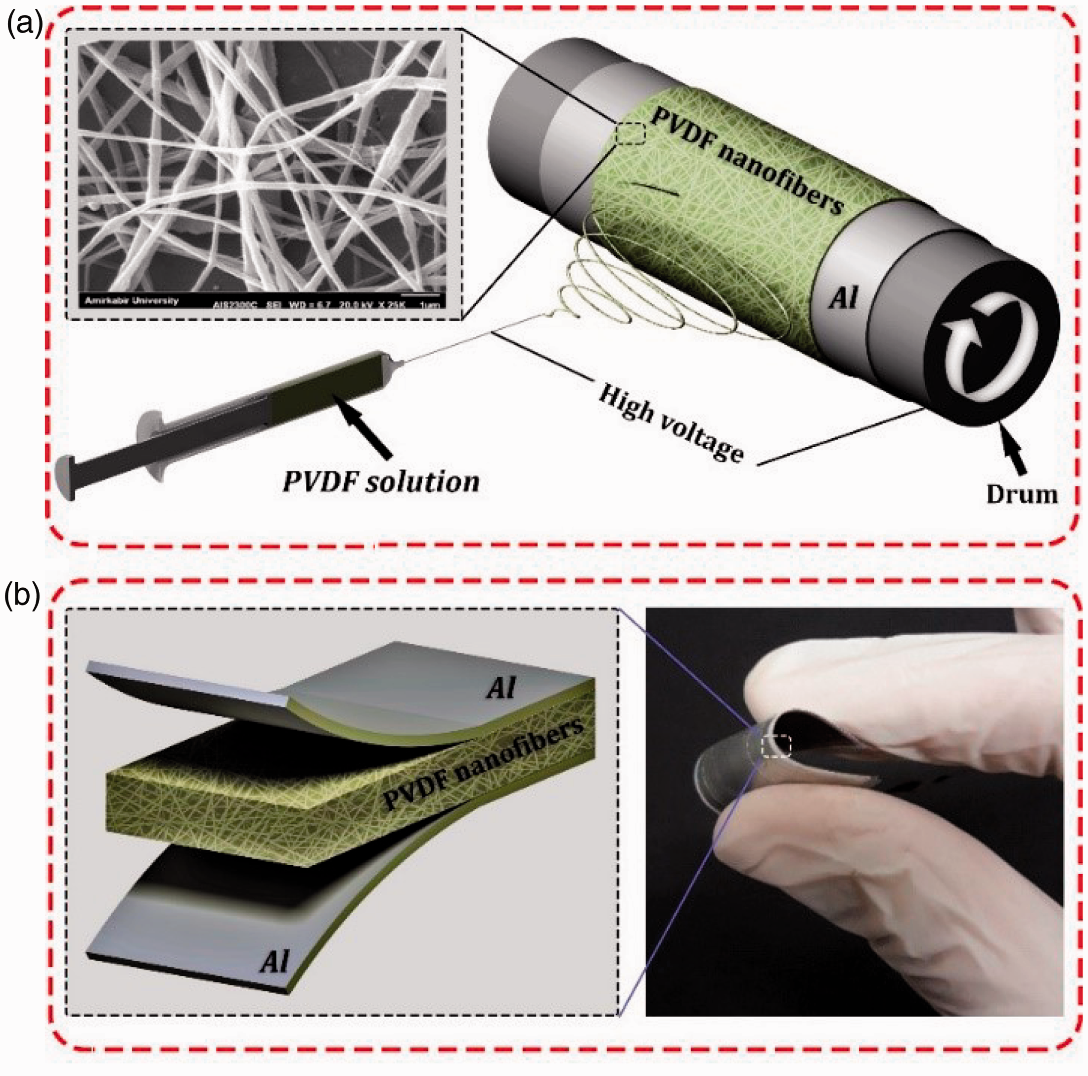
The schematic of device fabrication process (a) electrospun PVDF NFs and (b) fabricated device.
Characterization
Since the piezoelectric properties of PVDF mostly depend on its crystalline structure, crystal structures of PVDF NFs were evaluated by FTIR spectroscopy (Thermo Scientific Nicolet iS10 Spectrometer, Madison, USA) and X-ray diffraction (Equinox 3000 model, INEL, France) to identify of various phases in the collected PVDF NFs.
Figure 3 shows the FTIR spectrum of PVDF NFs in comparison with the original PVDF raw material. In the FTIR spectrum of original PVDF, the absorption bands at 530 cm−1, 615 cm−1, 763 cm−1, 795 cm−1, and 975 cm−1 are related to the α phase and the peak located at 840 cm−1 illustrates the characteristic peak of the β phase [33]. In the FTIR spectrum of PVDF NFs, only a small absorption band related to α phase is observed at 763 cm−1 and other characteristic peaks associated with the α phase are disappeared. Moreover, a new small peak at 1230 cm−1 related to β phase is appeared [20]. These results reveal a transition from α to β phase by electrospinning process.

FTIR spectrums of PVDF NFs compared with the original PVDF.
NFs can be obtained from the FTIR spectrum as follows in equation (1) [33]

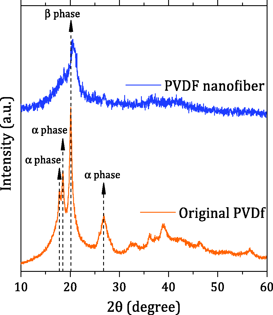
XRD patterns of PVDF NFs compared with the original PVDF.
The peaks of original PVDF at 2θ of 17.8°, 18.4°, and 26.9° correspond to the diffraction planes of (100), (020), (110), and (021) related to α phase. The major diffraction peak at around 20.3° corresponds to the reflection of the (110) plane of β phase [20,33]. In the XRD pattern of PVDF NFs, all characteristic peaks related to α phase are disappeared and only a major peak attributed to the β phase is observable. This result demonstrates the predomination of β phase in electrospun PVDF NFs, consistent with FTIR spectroscopy result. This confirms the remarkable transformation of α phase to polar electroactive β phase induced by the electrospinning process.
Experimental procedure
Since the prepared nanogenerator has been designed to harvest mechanical energy from human activity, the piezoelectric output of the device was evaluated under low frequency cyclic vertical impacts similar to the human walking motion. The experimental setup consists of an impactor, a load cell and an oscilloscope to monitor the device output response (Functional Fibrous Material Lab, Tehran, Iran). The impact test apparatus is shown in Figure 5. To measure the output voltage, the nanogenerator was placed on the plate under the impactor and the wires were directly connected to the oscilloscope. By applying vertical force on the device, mechanical energy is converted into electricity by a mechanism explained in a recently published work [21]. Briefly, in a PVDF electrospun mat, dipoles are placed along the mat thickness direction. Once a compressive force is applied on the top surface of the device, a piezoelectric field is generated inside the mat that separates electrical charges and drives electrons flow from an electrode to another (Figure 5). The experiment was repeated three times to study the results repeatability and the median of results was collected as the device response.

Impact response measurement and working mechanism of piezoelectric device.
Theoretical background
The governing equation of mechanical behavior for the present study is Cauchy’s first law of motion, which is given as follows in equation (2) [34]


where Di is the electrical displacement vector and q is the electric body charge. For this problem, two constitutive equations are employed as follows [34]


where
Figure 6 shows a schematic view of a piezoelectric material subjected to F1 and F3. For both loading directions, 1 and 3, V3 is measured. d33 and d31 can be determined using the specimen loading configurations shown in Figure 6(a) and (b), respectively. If the specimen is actuated along the 1-direction (F1), the induced voltage is determined by equation (7), while the obtained voltage in 3-direction (V3) is determined by equation (8), if the piezoelectric sample is actuated in 3-direction (F3)


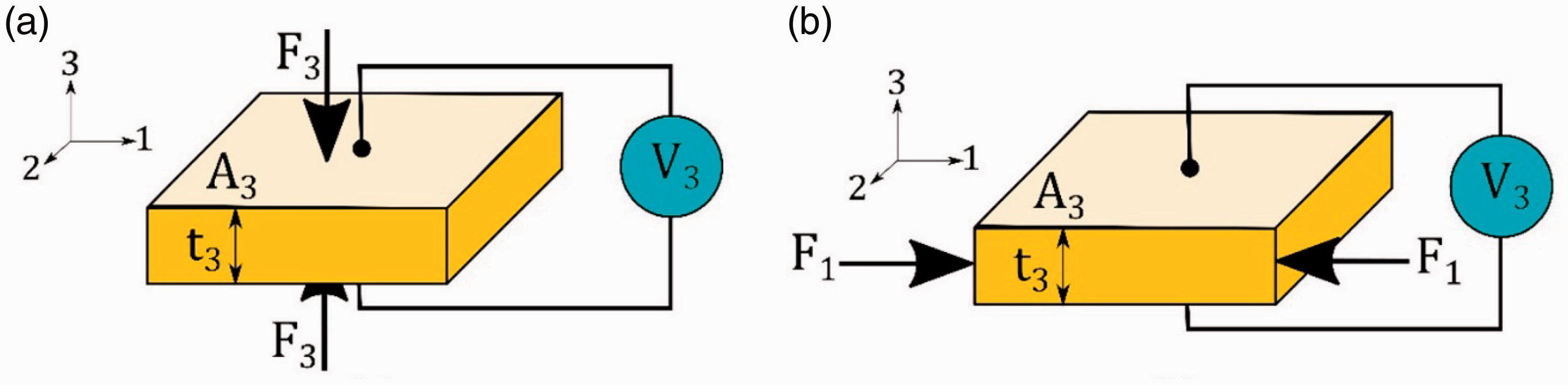
The schematic view of a piezoelectric material (a) F3 is applied and V3 is measured and (b) F1 is applied and V3 is measured.
Finite element analysis
FE modeling of impact test setup
In this section, FE model analysis of impact test setup is described. Furthermore, based on the present simulation a novel method would be presented in Section “Piezoelectric and dielectric evaluation using iterative simulation” to obtain the PVDF NFs piezoelectric and dielectric properties. Nonlinear multi-physics FE simulation is employed using advanced FE tool, Msc Marc 2015. The model includes three parts that are defined as base, impactor, and piezoelectric specimen shown in Figure 7. Mesh independence study is performed on the model to achieve the optimized number of elements. Thus, the sufficient element number for base, impactor, and piezoelectric specimen are determined as 300, 600, and 400, respectively. The boundary conditions are applied to the model according to the experimental configuration. The displacement of nodes at the lower side of the base is fixed along z-direction and the impactor is constrained through the z-axis. Surface to surface contact model is considered between impactor, piezoelectric specimen, and base. Linear elastic model including piezoelectric coupling is defined for the piezoelectric specimen model. According to the experimental device, rigid material model is considered for base and impactor. To validate the FE model, low cycle impact test device is fully simulated. Geometry and the boundary conditions of FE model are considered as they appear in the experiment.

FE model of low cycle impact test.
Obtained experimental applied force-time curve from the impact test is implemented into the FE model as the impactor external force. Figure 8 depicts the applied force-time curve for a single peak during the impact test. Since the diameter of the impactor has been measured 9 mm, the exerted pressure on the nanogenerator device is calculated 62.87 kPa. As it is seen, the figure extended to 150 ms, which can be considered as a settle time of a single cycle.

Applied force-time experimental curve implemented into the FE model.
FE modeling of the energy harvesting during human walking
Since this work aims to prepare a nanogenerator device to harvest mechanical energy from human walking, the PNIF as an energy harvester to implement in the shoe insole was introduced (see Figure 9). From a technical point of view, foam elasticity modulus is one of the important parameters, which will affect the nanogenerator output. Therefore, one of the objectives of this work is to optimize the elasticity modulus of the PNIF to achieve the maximum efficiency of energy harvester during walking. In order to optimize the foam elasticity modulus, a FE model is constructed as shown in Figure 9. “A” and “B” indicate the foot heel and the ball of the foot, respectively. Linear elastic behavior is considered for the human foot [35]. The foam model based on Ogden formulation (equation (9)) is defined for the foam layer as follows


FE model of PNIF in contact with human foot.
Mechanical properties of human tissue and considered foam.

Young’s modulus and Poisson’s ratio of the simulated nanogenerator are determined using classical laminate theory (CLT) and role of mixture based on each layer mechanical properties [39]. Young’s modulus and Poisson’s ratio of the PVDF layer were considered 2.3 MPa and 0.35, respectively [32].
The element numbers are increased to achieve a reasonable convergence in the obtained results. Therefore, the FE model consists of 12,169, 2400, and 1200 elements for foot, foam, and nanogenerator layer, respectively. The dimensions of nanogenerator and foam layers are considered to be 220 × 100 mm2. The thickness of foam is assumed 15 mm. The contact boundary condition is considered surface to surface touching between the human foot model and nanogenerator layer, and glue contact is defined between the foam and piezoelectric layer. As actually occurred during the human walking, a linear displacement is applied along z-direction to the foot model. Hence, the foam and nanogenerator layer are compressed together and the induced voltage from the nanogenerator layer is captured thorough the simulation time.
Result and discussion
Piezoelectric and dielectric evaluation using iterative simulation
Based on the piezoelectric material fundamental, piezoelectric coefficients, and dielectric properties are defined by d13, d33, and ε [40]. Determination of these constants needs to have particular experimental setup to calculate the piezoelectric coefficients [41]. In the present study, a new method is described to determine the piezoelectric and dielectric properties of PVDF NFs without any redundant experiments. This procedure is well-known as iterative simulation, which lets users to determine the material properties by iterating several simulations and numerical optimization simultaneously [42]. The utilized procedure flowchart to determine the piezoelectric and dielectric properties is shown in Figure 10. The procedure is implemented into ModeFRONTIER software to speed up the optimization procedure.

Iterative simulation flow chart to determine the piezoelectric and dielectric properties.
In order to start the optimization process, an initial value for each parameters should be considered. In the present work, the validated FE model was constructed by using the initial guess for the unknown piezoelectric constants given in [40,43]. A 50% change was then considered as the upper and lower bounds. By using try and error, the parameter bounds were changed to obtain the Normal distribution in the probability density chart. After each simulation, the obtained voltage-time output curve from FE model is compared with experimental curve and the error root mean square is determined. SOBOL algorithm is utilized to provide the design of experiment table to reduce the number of simulation [44]. Moreover, genetic algorithm (GA) is employed at every single simulation to minimize the calculated error in the every steps of optimization. For better presentation, the calculated error during the optimization process is divided to the maximum error among all determined errors called normalized error. Figure 11 shows the normalized error determined for all design points. The overall trend of the normalized error is converged, and the minimum value is achieved for design ID 98 with 0.2426 normalized error. The stochastic nature of GA leads to the random fashion of error values.

Normalized error convergence determined for all design IDs during optimization.
In the present study, the optimized piezoelectric coefficients are successfully determined in 120 iterations. The optimized permittivity and piezoelectric coefficients are reported in Table 2. Figure 12 illustrates the probability density of each piezoelectric coefficients during the optimization process. The reported optimized value of each coefficient is reasonably placed at the middle of a normal distribution. It reveals that the upper and lower bounds considered for each design variable in the optimization process were appropriately assumed. The maximum number of counts shows the maximum possibility for a candidate as an optimum value.
Optimized permittivity and piezoelectric coefficients determined by iterative simulation.

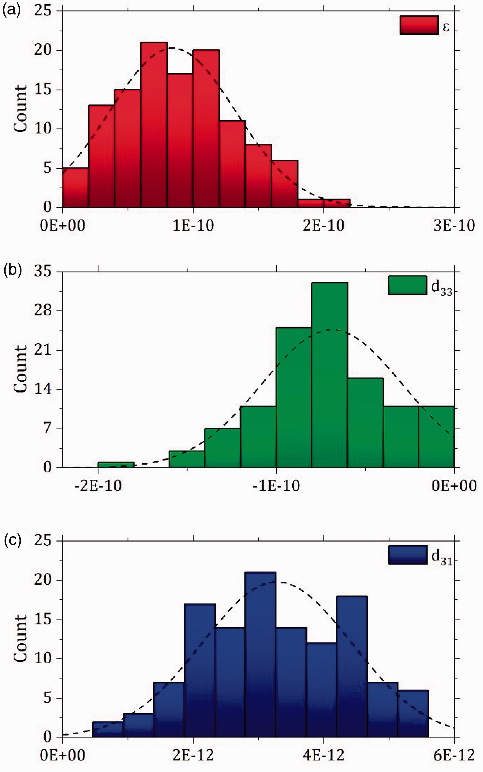
Probability density of (a) ε, (b) d33, and (c) d31 during the optimization process.
After the described optimization process, the experimental voltage-time (under 4 N impact force equal to 62.78 kPa) was compared with voltage-time curve obtained from FE model using the optimized piezoelectric properties, as shown in Figure 13. A reasonable agreement is observed between the numerical and experimental curves. As Figure 13 indicates, the FE result demonstrates an excellent accuracy to predict the maximum voltage. Nevertheless, the model can estimate the piezoelectric specimen behavior under impact test with an appropriate accuracy for the other points.

A comparison between experiment and FE using optimized piezoelectric properties.
The influence of foam modulus on the walking energy harvesting
One of the effective parameter to harvest the energy from human walking is the design of shoe itself. In this section, the effect of PNIF stiffness known as foam modulus is investigated numerically by FE analysis. As provided in Table 1, the elasticity modulus of commercial foam used in PNIF is given 151 kPa. Hence, a variation range between 100 and 220 kPa is considered to study the effect of foam modulus on the harvested energy during walking and also foot loading. It is worth to note that all parameters are remained constant for each simulation.
Figure 14 depicts the variation of FE predicted voltage by changing the PNIF modulus. Ten design points are defined and solved by numerical simulation. Third-order nonlinear curve is also fitted to the calculated data to determine the maximum value of voltage related by the foam modulus. Following, the used third-order equation is provided

Variation of FE predicted voltage by changing the PNIF modulus.
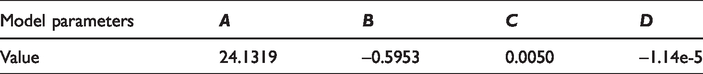
Cubic polynomial model parameters.
The recovery time of foams during squeezing are increased by reducing their modulus. In the other words, more time is needed for soft foams to recover their deformation after unloading. If the working frequency of such foams is applied higher than their recovery time, it seems that the foam never come back to the uncompressed shape. Therefore, if very soft foam is considered in the shoe insole, compressing and uncompressing is not actually happen. It means that the nanogenerator does not feel significant strain and no reasonable voltage might be generated. In contrast, if the foam modulus is increased higher than the critical point (here is 211.27 kPa), the required deformation is not occurred as much as needed for the PNIF energy generation. The squeezing process of the foam layer during the foot loading is shown in Figure 15. The maximum equivalent elastic strain is calculated not only under the foot heel (“A” in Figure 9), but also under the ball of foot (“B” in Figure 9) which is fully deformed as well. Thus, the maximum power is generated under the “A” and “B” regions. Figure 16 illustrates the equivalent elastic strain iso-lines of nanogenerator layer at the end of simulation, once the foot has fully deformed the shoe insole.

Six snap shots of equivalent strain in the foam layer during the foot loading from (a) to (f) 0% to 100% progress (20% step).
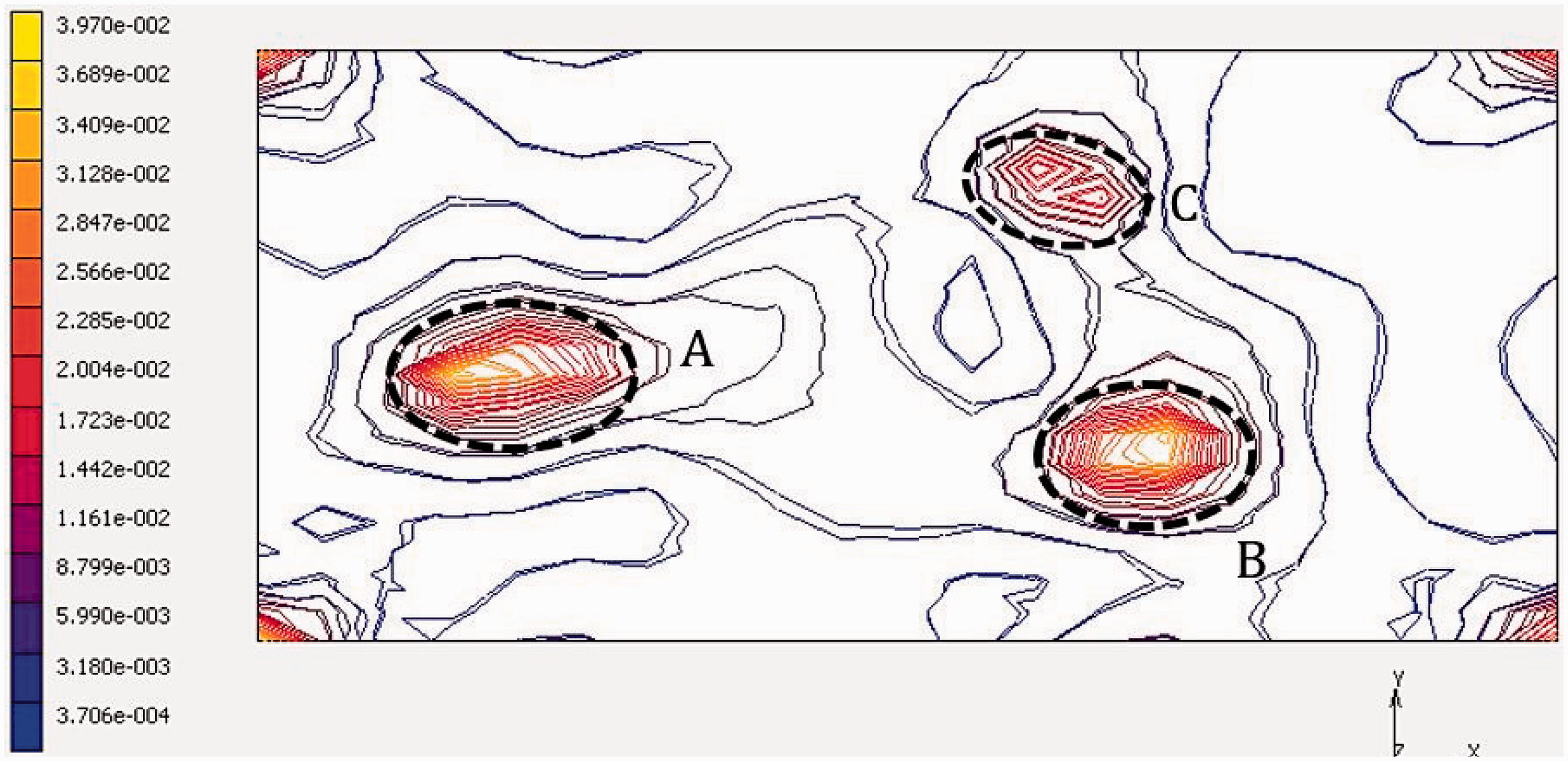
Equivalent elastic strain contour lines of nanogenerator layer.
As it is annotated in Figure 16, three distinct regions are clearly observed which are shown by the dense contour lines. As stated before, “A” and “B” collect the maximum strain compared with other points. Moreover, “C” region is also predicted as a high deformed point during the loading. As sum up, the maximum harvested energy is generated from “A”, “B,” and “C” regions, respectively.
Furthermore, Figure 16 suggests to minimize the fabrication cost and maximize the device efficiency, it seems superior to use only piezoelectric material under “A”, “B,” and “C” regions simultaneously. It is worth to note that, Figure 15 shows the equivalent strain on the shoe insole foam, whereas Figure 16 depicts the equivalent strain on the nanogenerator layer stuck on the shoes insole foam.
Conclusions
In the present study, a novel approach based on FE iterative simulation was employed to obtain the electro-mechanical properties of a piezoelectric nanogenerator fabricated by electrospun PVDF NFs. The difference between simulation results and experiment was considered as the objective function. GA was utilized to minimize the defined error to determine the piezoelectric and dielectric properties with a reasonable accuracy. As a case study, the foam modulus used in shoes insole for walking energy harvesting was numerically optimized to obtain the maximum energy efficiency during human walking. The maximum generated voltage was determined 15.1 V achieving for 211.27 kPa PNIF modulus. Critical regions on the foam were also identified to achieve the maximum efficiency with minimum usage of PVDF layer.
Footnotes
Declaration of conflicting interests
The author(s) declared no potential conflicts of interest with respect to the research, authorship, and/or publication of this article.
Funding
The author(s) disclosed receipt of the following financial support for the research, authorship, and/or publication of this article: Amirkabir University of Technology and INSF (Grant No. 97016813).