
Abstract
In present study, electronic vests were designed by using conductive textile material and electronic circuits. The objective was to sense armed assaults and transmit the coordinates and position of gun fire instantly to the headquarters. Another objective is to provide instant emergency respond for injuries at vital sections of the body and to capture perpetrators quickly. To reach the desired targets, silver-coated conductive yarn, polyamide plain weave and various circuit components were used. Silver-coated conductive yarn was used to form sensor unit of the electronic vest and stitched over polyamide fabric in 3 mm intervals. Main vest section was prepared in medium size and conductive-yarn sensor unit was installed to the vest with a velcro system. Classical and Surface Mount Device (SMD) circuit technologies were used in circuit units to sense bullet intrusion and transmit the case to operational center. Two different circuit designs were tested at a shooting range and the outcomes were assessed and compared for two different circuits. It was observed in shooting tests that both vests were able to sense bullet intrusions in case of an assault and to transmit the shot message with the coordinates and position of the shoot correctly.
Keywords
Introduction
Developing technology, increased competitive conditions, and customer expectations have increased the production of innovative, multi-function, and special-purpose products in textile industry [1]. According to Meinander (2005), smart textiles, smart fabrics, and interactive textiles are the products able to monitor or develop interactions with the environment or the user [2]. Among these products, smart textiles represent the materials able to detect and respond to environmental stimulants [3]. In a broader sense, smart textiles are defined as the textile materials or textures able to sense through an active control mechanism and react against environmental stimulants [4]. According to Stoppa and Chiolerio, smart textiles are in continuous interaction with their environment or the user and they are composed of yarns, filaments or fibers-like textile products weaved or knitted together or processed together as bonded fabric [5]. As it can be inferred from these definitions made by different researchers, smart textiles are able to sense the changes in environmental conditions and respond or react against them. Such reactions may be electronic in some cases or chemical or physical in some other cases. Progress in chemistry, electronic and computer sciences, wearable computers, nano technologic fibers, high-strength fibers, and similar materials have been developed [1].
Among smart textiles, electronic textiles in which electronic pieces are used together with textile are becoming quite popular in recent years. Today, such products are considered under the concept of textronic. Electronic textile production covers a broad range of products from conductive fiber to special spacesuits. Progress in electronic industry let the production of more comfortable, more resistant and more applicable products. Together with the progress in conductive fiber and conductive yarn technologies, sewn conductive surfaces have been produced.
Considering the recent developments in electronic textiles, the present study was conducted to design washable, flexible, reparable, and re-useable electronic vest by using superconductive yarn and SMD circuit technology and to provide this newly design vest to the service of individuals who wish to take security service.
Design factors and characteristics for wearable electronic vest
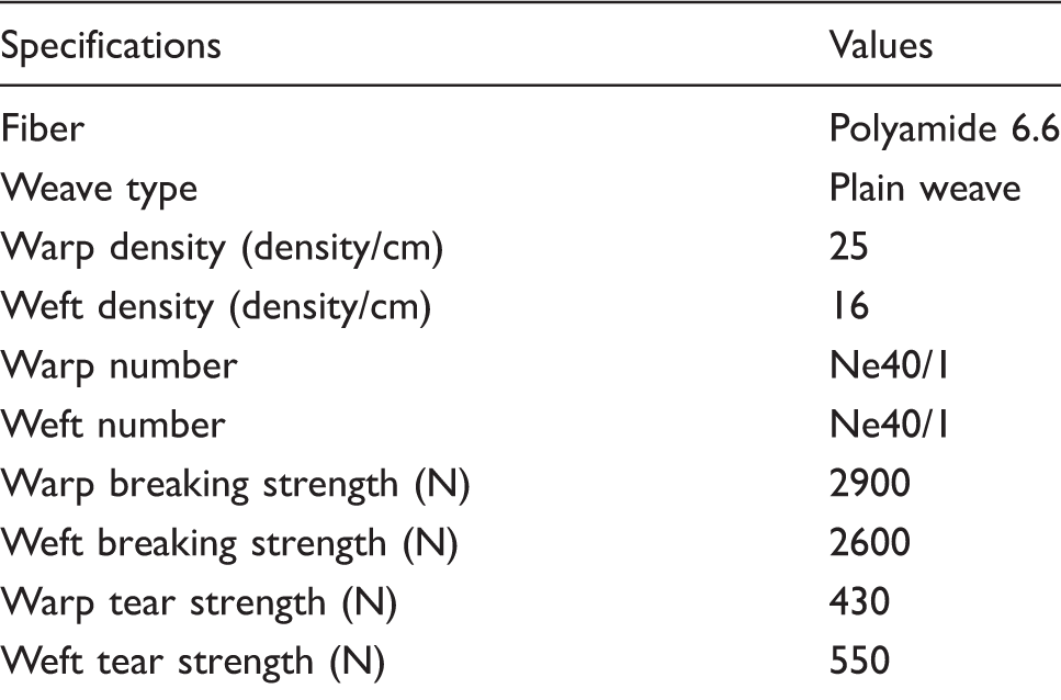
Water repellency: Water repellency prevents water intrusion into the textile through creating a quite tiny hydro-fob film over the fibers [6]. The purpose of using water repellent fabric is to prevent the potential damage of liquid contact on electric circuit current. Type of fiber: Fibers constitute the bases of textile and they are either natural or artificial textile materials with certain length and diameters [7]. The fiber characteristics are selected based on the intend of use and the most proper fibers are selected for the relevant production. Fibers are selected commonly based on various fiber characteristics like durability, fineness, abrasive strength, waterproofness, etc. [7]. Type of weaving: Type of weaving in textile fabrics influences the maximum density through the intersection ratio in warp and weft yarns. Besides density, type of weaving also influences weight and thickness of the resultant fabric [8]. Type of weaving is an intersection type of warp and weft yarns in textile fabric and plain weave has the strongest texture [9]. Locomotion: Several factors such as fabric thickness, type of weaving, yarn number, finishing processes, type of stich, and fabric elasticity influence the locomotion of the individual wearing the garment. Stich sizes, lines, and types also influence the locomotion [10]. Thermal comfort: Thermal comfort is generally influenced by several factors such as fabric texture, natural fiber chemistry, and external factors [11]. Age, physical state and health of the user, fiber texture and yarn type, fabric texture, textile design, ambient relative humidity, temperature and wind speed also influence thermal comfort [12]. In present fabric texture, polyamide texture was used together with plain weave and conductive yarns. Since the vest used in the system covers the chest and abdominal sections, air inlet to body is provided from several points easily. The fabric used in this system is the standard fabric preferred by police and military organizations in ballistic vest; therefore, it can conveniently be incorporated into inventory. Conductivity: One way of creating electronic textiles is to use electrically conductive yarns [13]. Conductive fibers can be classified into two general categories, those that are naturally conductive and those that are specially treated to create conductivity and the other is coating of textiles with metals [14]. In present design, silver-coated polyamide yarn was preferred for higher conductance and easy utilization.
Material and method
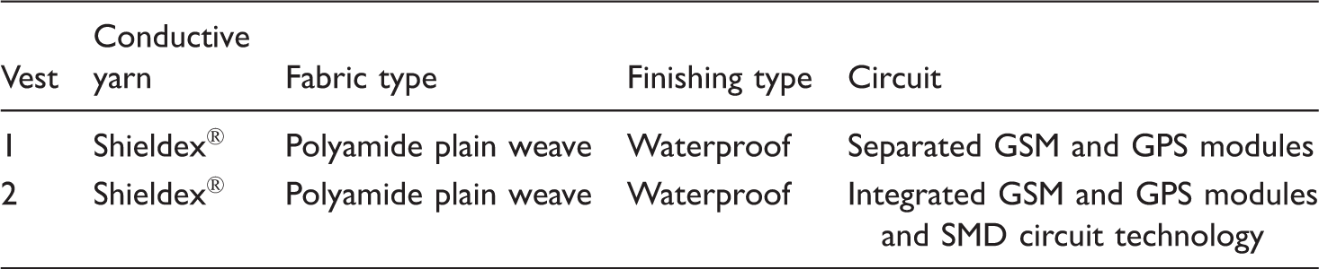
Sample vest features.
Manufacture of vest components
Main vest
Technical specifications for Polyamide 6.6 fabric.
Fabrics were initially cut in patterns, then these pieces were stitched to each other to form the main vest unit (Figure 1). The most important components of main vest section are the sensor and the pocket located behind the vest to carry velcro system connecting main vest components and circuit board. The velcro system and pocket section located behind the vest to place circuit are presented in Figure 2.
Main vest. Main vest: (a) pocket section and (b) velcro system.

Circuit board pocket behind the main vest was made large for the first circuit designed and this section can be reduced by 1/3 for the second circuit.
Sensor unit
Technical specifications for conductive yarn.

Since sensory unit is to be formed with conductive yarn in present design, Shieldex® 50 Ω/m ± 10 Ω/m yarns were stitched over the fabric in 3 mm spacing as a single unit as shown in Figure 3. Since it is significant to stich the yarn as a single piece without breaking, stich of both front and back sensor units were performed without damaging the yarn.
Stich of conduction yarn for sensor unit: (a) schematic view of conductive yarn; (b) and (c) stitched sensors over the front and back pieces of the vest.
Following the preparation of sensor unit, main vest and sensor unit components were connected with velcro system. The final form of connected parts is presented in Figure 4. The components connected through velcro system can easily be separated and components can then be washed, repaired, etc.
Final form of connected components.
Since main vest part and sensor units were totally manufactured from textile fabric and yarn, they can be washed and reused.
Circuit mechanism
Two different circuit mechanisms were designed. GSM and GPS modules were separate in the first design and they were designed as a single unit in the second design. Initially circuit diagrams were drawn in Proteus software and their logical operations were checked with this software (Figures 5 and 6). Proteus software allows users to put circuit components into computer atmosphere and to check whether or not the system properly operates. As presented in Figures 5 and 6, components of the circuits designed for two systems were selected one by one and placed with Proteus software and proper operation of circuit boards was checked with the software.
The first circuit on Proteus program: (a) circuit diagram; (b) drawing circuit components in software. The second circuit on Proteus program: (a) circuit diagram; (b) drawing circuit components in software.

Circuit components used in circuits
There some differences in dimensional and technological properties of the first and the second circuit. Microcontroller, antenna, GPS and GSM modules used in the first circuit and the components of the second circuit are different from each other. These circuit components with basically the same functions in both circuits have different dimensions, operations speeds, and technologies. SMD technology was used in the second circuit. This technology is implemented by using surface installation technology instead of classical pinned circuit components. In this way, circuit components are directly installed over the surface without pins. While pinned circuit components are inserted into the holes over electronic cards and soldered, SMD components are installed over the card and fired. SMD circuit components occupy less space than pinned circuit components. In this way, quite smaller circuits can be designed. Circuit components used in both circuits and their properties are listed below:
GPS module of the first circuit: “Nano GPS click” brand GPS module was used to determine coordinates. The device has Nano hornet GPS module with initial set timing of max 1 s, (TTF), tracking precision −163 dBm and power output 3.3–5 V. GSM module of the first circuit: “GSM click” brand GSM module with dual band frequency of GSM/GPRS 850/900 MHz and power output of 3.3–5 V was used to transmit the coordinates determined in the system to operational center. SD card of the first circuit: Large and micro SD cards with 2 GB capacity were used to simultaneously store the system data. Microcontroller of the first circuit: “Atmel Mega 328 P” brand microcontroller unit with 32 KB flash memory, 6-canal 10-bit A/D convertor, and 1.8–5 V power was used as the brain of the circuit. GSM and GPS module of the second circuit: In the second circuit, instead of using separate GSM and GPS modules as it was in the first circuit, “Adafruit FONA 808 Shield—Mini Cellular GSM + GPS for Arduino” brand GSM-GPS module able to perform the functions of GPS and GSM modules on a single module was used. The integrated module is presented in Figure 7. SD card of the second circuit: Large and micro SD cards with 2 GB capacity were used to simultaneously store the system data. Microcontroller of the second circuit: “Atmega 2560 16AU” brand microcontroller unit with 256 KB flash memory, 8-bit and SMD was used as the brain of the circuit. Circuit batteries of the first and the second circuit: 3.7 V lithium-ion batteries were used in both circuits. With these batteries, the first circuit has a nonstop operation of 125 h and the second circuit has a nonstop operation of 140 h. Lithium-ion batteries are rechargeable batteries. Adafruit FONA 808 Shield GSM + GPS brand integrated module.

Following the drawing of circuit diagrams, each circuit was placed on circuit board and final circuits were achieved. In both circuits, separate access was provided for front and back part of the vest, in this way, assaults from the front or back can be identified separately. Designed circuit components were placed on circuit boards and data processing codes prepared in Ardunio software separately for each circuit were recorded on microcontroller. With this software, the system was able to control the circuit components and sensors in case of a shot and send the desired warming message to the operational center. The final state of the first circuit is presented in Figure 8 and the final state of the second circuit is presented in Figure 9.
The first circuit: (a) circuit board; (b) final state of first circuit. The second circuit: (a) circuit board; (b) final state of second circuit.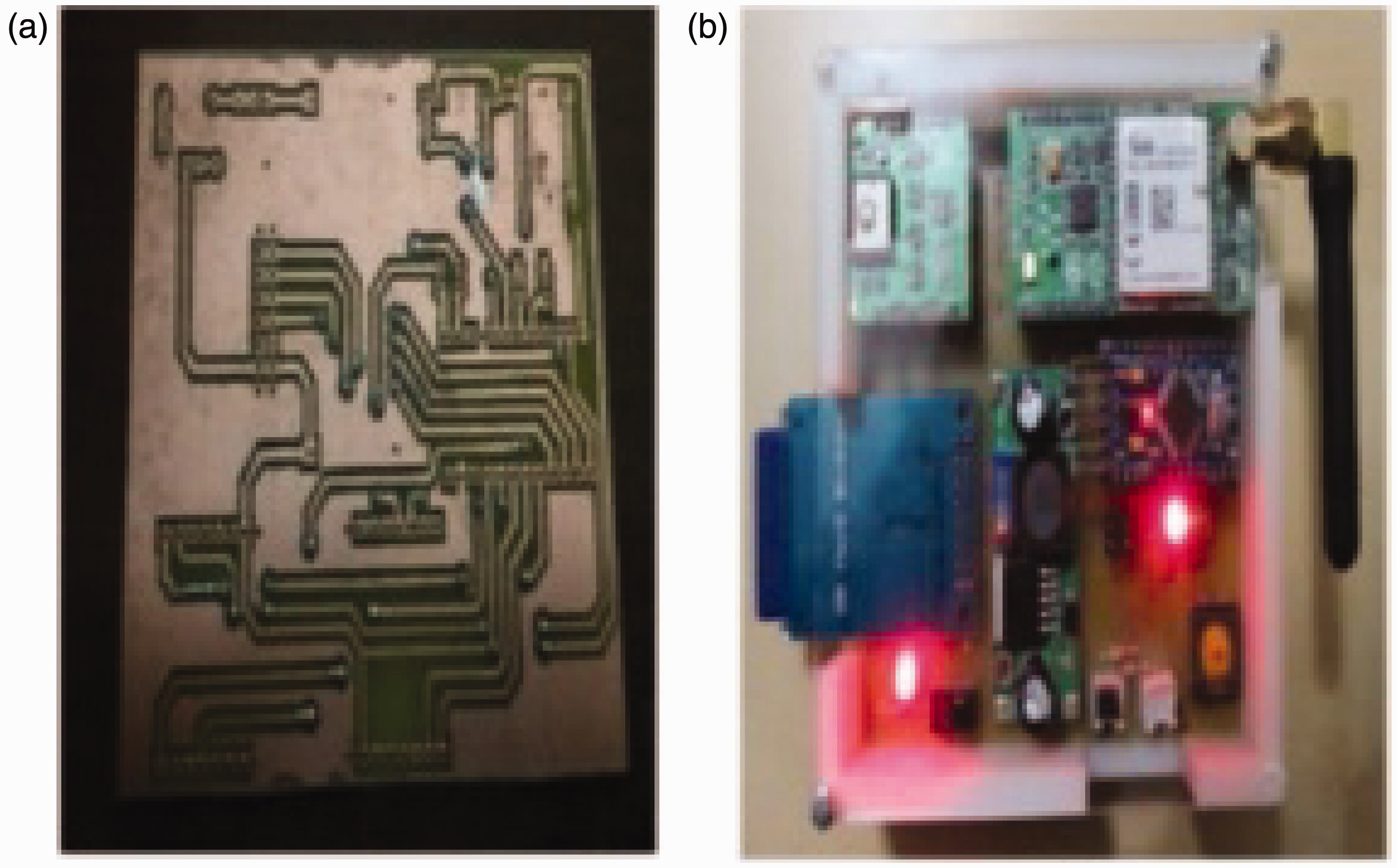

As can be seen Figures 8 and 9, ready-to-use circuit boards were placed into pocket sections over the main vest and flexible tinny cables were used to connect circuit boards with sensor parts through the transition section created in the pocket. In connection parts, conductive yarns and flexible cables are separable when desired. The section in which flexible wire passing to sensor unit through the inner part of the pocket is presented in Figure 10.
Connection of flexible wire with sensor part.
Following the connection of circuit boards with sensor parts, the velcros over the pocket section was closed to protect circuit boards. The in-built antenna over the circuit boards is able to transmit location information to the circuit board.
Shooting testing stage
The first and second generation circuits were placed in circuit pockets of the vests and two different vest types were tested at a special shooting range. The vests were fired from 20 m distance with a Sarsılmaz brand gun (9 mm × 19 mm bullets). Following the shooting, deformations over the vests and messages from the circuits were checked (Figure 11).
Shooting test of the vests.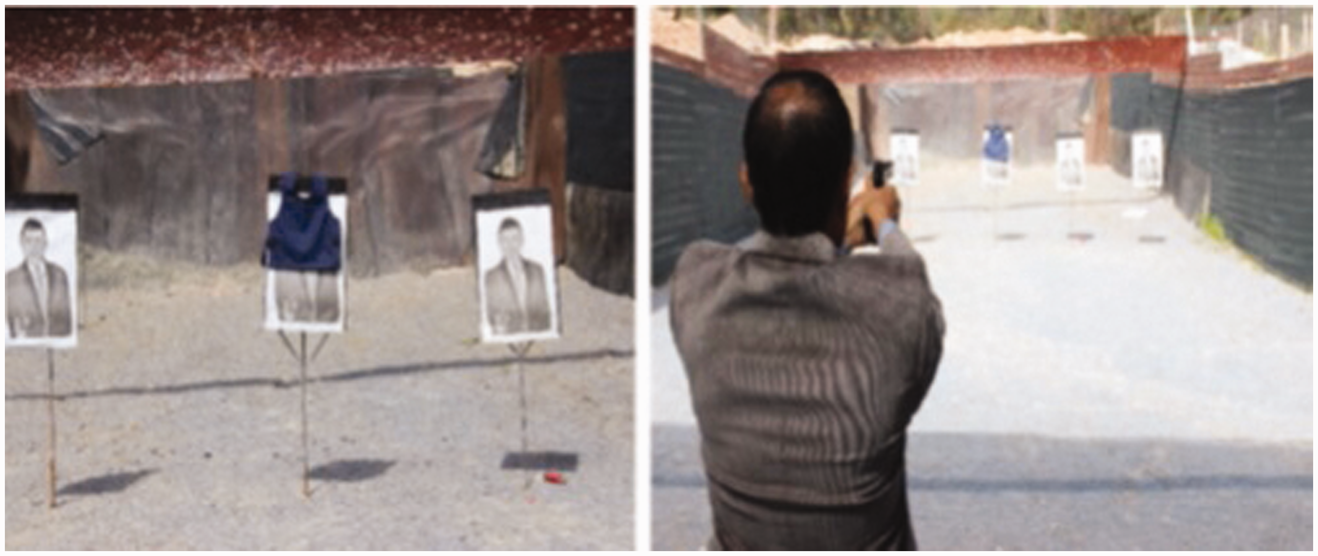
Washability testing stage
Breaking and conductivity test results after washing.

Significance of Bold Values: % Changes show the effects of washing on breaking strength and conductivity in comparision to non-washed sample.
Flexibility testing stage
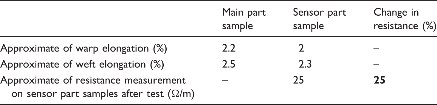
Apart from circuit part, electronic vest was totally made of textile material. Therefore, it was wearable. To present the elasticity values of the vest, elasticity tests were performed for main vest textile and sensor textile. Five samples were taken from each textile component and samples were conditioned at 20℃ ± 2 temperature and 65 ± 2% relative humidity for at least 16 h. Elasticity test device was used in elasticity tests. Spring dynamometer was used in tests and strain at 30 N load was measured in accordance with M&S test method.
Repairability testing stage
This stage has been done after shooting test. Breaking conductive yarns have been repaired with new and short conductive yarn by gluing with textile glue with rosin. Gluing or sewing methods can be used according to conditions. Some ready to use short fabric parts with conductive yarn can be made, so it provides faster repairing in the area. After repairing, resistance on the repaired sensor part has been sized. Repairing provides the design to be used longer, so it can be called as a “long-life design.”
Results and discussion
Circuit sizes
Considering the technological progress in electronic vest design, two different circuit boards were designed. Operational principles are the same in both circuit boards, but the electronic materials were different. Such differences were mainly because of single unit modules, antenna differences and SMD circuit technology. These differences let to have smaller circuit sizes, easy utilization, and better operational timing. The size of circuit designed for electronic vests are presented in Figure 12.
Circuit sizes.
There were about 70% differences between the surface area of the first and the second circuit, because of the differences in materials and technologies used in circuit design and there was about 80% difference in volumes of the circuits. Such differences were found to be quite significant for less space occupation of the system. The antenna used in the second circuit was flexible and thus it was easier to use than the first one.
Electronic vest test results
Deformations over the vests
Operation of the present designs was based on the sense of bullet deformation over the vest surface independent from the distance. “How far is the shooting distance” does not have any positive or negative influences on system performance. The vests were worn over the dummies in shooting range and gun was fired to the first and the second circuits from 20 m distance at two different times. Initially, following the gun fires, deformations were detected over the vests (Figure 13).
Bullet penetration into vests with two different circuit designs.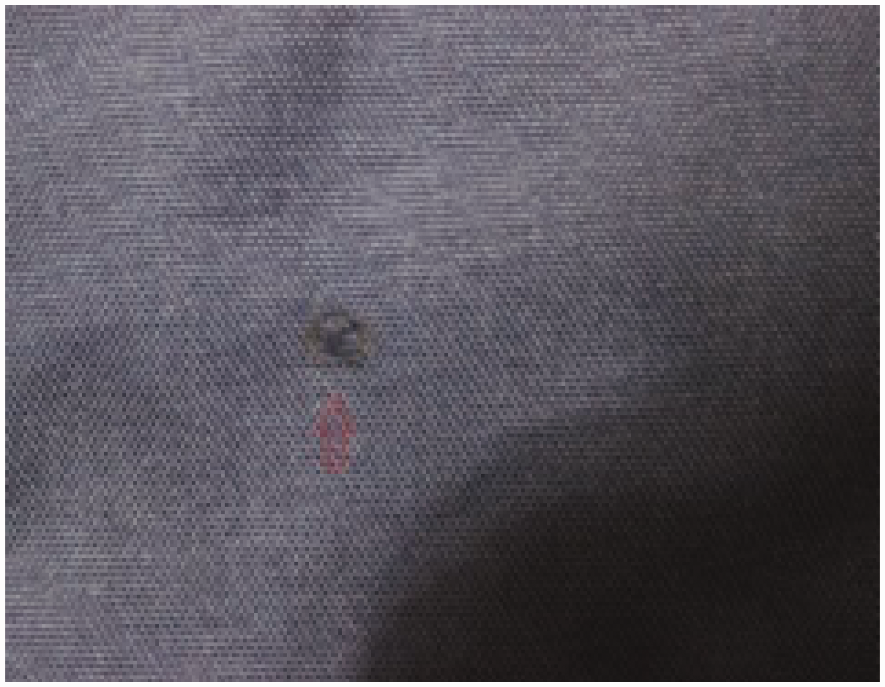
As can be seen in Figure 13, bullet intrusions into the vest created a hole of 5 mm in diameter. It did not create any other damage or burns over the vest. When once the bullet touched the conductive yarns on vest, these special yarns were broken by bullet and system understood “the cut of yarn” due to no electricity on circuit. Electricity cutoff over the system is interpreted as a bullet intrusion by circuit processor and the case is then confirmed by four satellites in the protocol of GPS module and the resultant coordinates are sent to operational center as a message. Since the message to be created was prepared in Ardunio software and loaded to processor, front/back, North/South Coordinates, and time of shot are processed and included into the message.
Transmission of “shot” message
The task expected from the vests after a shooting incidence was to transmit the coordinates of shooting incident and the direction of shooting to the operational center in case of a bullet penetration. In testing fires, the deformations over both vests were sensed by the system and a message was sent to the headquarters. While the first circuit delivered the message in 15 s after shooting, the second circuit transmitted the message to the headquarters in 4 s after shooting (Figure 14). Shot message contained coordinates and way of shooting on body, so headquarters could see the coordinates on time.
The messages delivered by the vests to the headquarters after shootings: (a) the message delivered by the first circuit; (b) the message delivered by the second circuit.
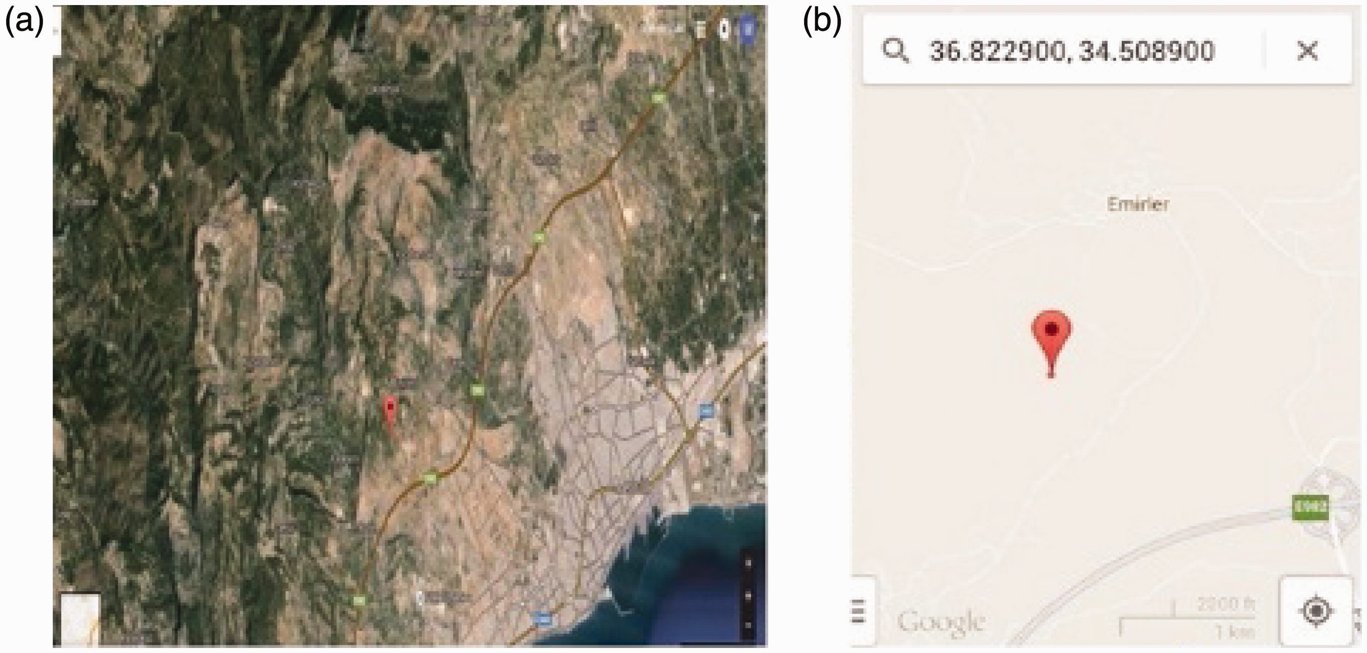
Transmission of coordinates to map and coordinate verification
As it can be seen from Figure 9, the system was able to send the message including shooting position and coordinates to the headquarters. Upcoming coordinate information was then transferred to the map through the software and the coordinates were verified with the actual coordinates of shooting location. Mobile phone GPS location coordinates independent from the system were used to confirm system coordinates. In the message received from the vest carrying the first circuit indicated the shoot position as “front” and the coordinates of the shooting location based on data received from four different satellites as “36.8230 North–34.5088 East”; the message received from the vest carrying the second circuit indicated the shoot position as “back” and the coordinates of the shooting location based on data received from four different satellites as “36.8229 North–34.5089 East.” It was observed that the coordinates sent by the system was accurate and the direction of shooting was correct (Figures 15 and 16).
The message sent by the first vest and coordinate verification: (a) coordinates transferred with the message; (b) actual coordinates of the shooting location. The message sent by the second vest and coordinate verification: (a) coordinates transferred with the message; (b) actual coordinates of the shooting location.
Shooting from the front or back did not have any negative or positive impacts on system performance. The system was able to send the position of shooting only as front or back, it was not able to provide an organ-based position (like hearth region, stomach region, etc.). Such information may be included in further designs. The size of deformation was similar in both vests with two generation circuits. Since the system was designed to sense bullet deformation, separate designs should be performed for shrapnel-like smaller pieces than a bullet. There was a high difference in message timing of two generation circuits from the intrusion of the bullet into the vest. The new generation circuit of the second vest was able to deliver the message in quite shorter time than the first vest, since it was composed of more advanced micro control and modules. The position information sent through the message was quite accurate in both circuit designs. The pocket to place the circuit covers a small section behind the vest, but prone to bullet attacks. Therefore, the pocket section may be reinforced with bullet-proof fabrics to provide a sustainable operation under every condition.
Washing, flexibility, and repairing test results
Washing test results
Washing test conditions have been given in Table 4.
It has been seen that breaking and conductivity test results haven’t been affected negatively after 15 washings. System can still remain resistance on conductive yarns and there is no breaking on the fabric in lower weights. Change in breaking strength in main part has become max −3.44% in warp breaking strength, −7.69% in weft breaking strength, change in breaking strength in sensor part has become max −14.81%. Change of strength in sensor part is higher because of sewings on fabric surface. Sewing causes damage on fabric surface, so fabric can’t use its complete power capacity against breaking force. Maximum change in sensor part is a bit high (−14.81%), but it isn’t forgotten that 90 min washing time and 90℃ washing temperature are hard washing conditions for clothings. Main part and sensor part have shown less decrease in lower washing time and washing temperatures in terms of breaking strength. In lower washing conditions, change in resistance is lower, too. Maximum change in resistance is 20%, this change is not so important because system remain working without any problem. Hard washing conditions can affect the conductive yarn surface, so resistance becomes higher. As a result, it is seen that lower washing time and lower washing temperatures give better washing results, so these soft washing conditions can be preferred for longer usage of electronic vest. In some conditions, dry cleaning can be applied on electronic vests, so there will be less decrease in breaking strength and resistance measurements.
Flexibility test results
Flexibility and conductivity test results.
Repairing test results
After shooting, there has been a hole on both main part and sensor part (Figure 17(b)). System can be repaired by using conductive yarn and small fabric part by using sewing and gluing. A hole of main part has been repaired with space fabric by gluing with textile glue with rosin (Figure 17(a)). After repairing main part, breaking on sensor part has been started to repair by using sewing with needle (Figure 18).
Main part of the vest: (a) repaired appearance of the main part; (b) hole on the main part after shooting. Repairing of the sensor part by knotting and sewing.
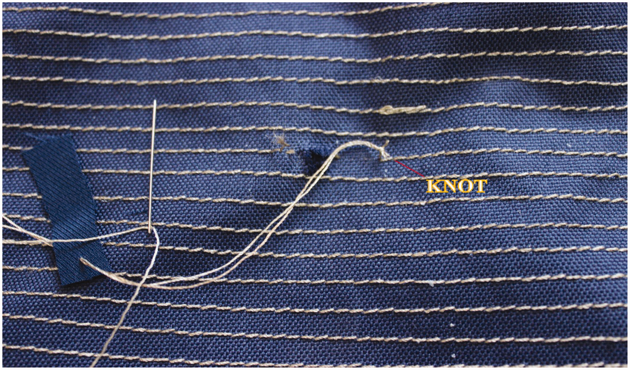
Broken conductive yarn has been knotted with new conductive yarn (Figures 18 and 19). After knotting of the conductive yarn, this complete conductive yarn has been sewed on small space fabric, and then this new space fabric has been gluing on the hole (Figure 19a). Gluing is a faster solution in dangerous areas, but sewing is a more durable way in comparison. After repairing of the sensor part, conductivity on sensor part has been sized and it has been found 30 Ω/m, so system can still remain working without any problem.
Repairing of the sensor part: (a) repaired sensor part appearance; (b) hole on the sensor part before repairing.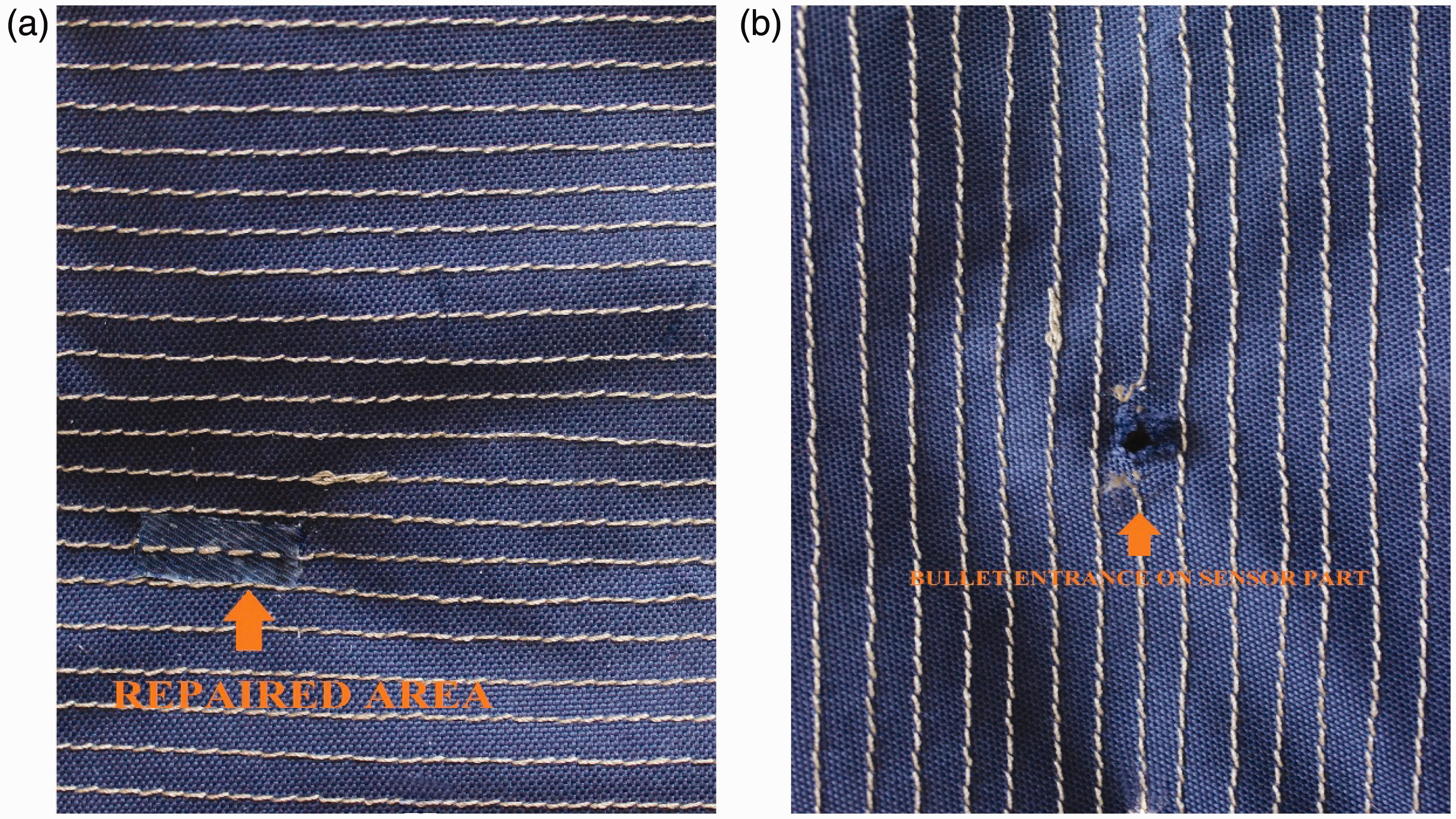
Conclusion
Security forces are under increasing attacks in every day. With this newly designed vests, the location of shooting or attack can rapidly and accurately be determined, emergency response can be provided on time, perpetrators can be captured instantly. In present designs, instead of readily available sensors, the ones made of conductive yarn were used. In this way, a washable, flexible, more comfortable, reparable, and long-life design was performed. Since all materials constituting sensor and main vest are textile yarn and fabric, they were all washable. In electronic textile designs, since electronic sensor and materials are generally used so many times, designed surfaces are generally rigid and fragile. Therefore, since sensor and main vest components were made of textile fabric in present design, it had more advantageous flexibility and comfort properties than the other electronic textile surfaces (Table 1-2-4-5). The broken section of conductive yarn with bullet intrusion can be knotted with a strong conductive yarn and electric current can be resupplied. With these new designs, the targets of instant emergency respond, instant information and instant capture of perpetrators were achieved.
General outcomes of the present study carried out for ballistic protective electronic textile product design are provided below:
In case of a gun fire from 20 m distance, both circuits of the system were able to transmit the location of shot (either from the front of back) correctly (Figure 14). Following the gun fires to the system, the first generation circuit was able to send the message in 15 s and the last generation circuit was able to send the message in 4 s. In case of a gun fire from 20 m distance, both circuits were able to transmit shot coordinates correctly (Figure 14). In case of a gun fire from 20 m distance, correct shot coordinates (36.8230 North–34.5088 East and 36.8229 North–34.5089 East) of both circuits were proved with the coordinates of the shooting range where shooting tests were performed (Figures 15 and 16). The first generation circuit had a continuous operation of 125 h and the last generation circuit had a continuous operation of 140 h. Such durations were tested by running the system until the end of their energies. The system with last generation circuit, modules, and SMD technology brought a size reduction as compared to the first generation circuit system (about 80% reduction in volume). Less volume and easy –carry on of the system was provided with the last generation circuit design. Since flexible antennas were used in the last generation circuit design, they provided flexibility in operations and thus were more advantageous than the first generation circuit system (Figures 8 and 9). The damaged sections can be repaired with conductive yarn and the same vest can then be reused (Figure 19). Washing and Flexibility tests show that system can remain working without any problem, so such features provide system a long-life design. Lower washing conditions provide less decrease in breaking strength and resistance, so lower washing applications are advised for longer-lasting electronic vests. In some cases, dry cleaning can be applied for lower decreases.
Since the present study is a ballistic study, it may recall a protection against bullet (like bullet-proof), the present system does not provide direct protection. The primary target was to provide faster aid to military personnel and to reach the incident location promptly. In this way, larger cases may be prevented. In present designs, quite smaller circuit boards were able to be integrated into the textile structure. Textile-originated sensors, washability, and reparability constitute the greatest points of these vests. In future designs, circuits may get smaller; other flexible materials can be used instead of conductive yarns; new designs can be performed for lower parts of the body; similar systems can be integrated into other textile products; more precise positioning for bullet intrusion can be achieved.
Footnotes
Declaration of Conflicting Interests
The author(s) declared no potential conflicts of interest with respect to the research, authorship, and/or publication of this article.
Funding
The author(s) received no financial support for the research, authorship, and/or publication of this article.