
Abstract
In this work silver nanowires were synthesized and drop casted on a commercial spandex yarn to create an electrically conductive spandex. These yarns are used in a wearable electronic application as touched-based capacitive sensor to wirelessly control a toy robot, BB8. Touching the conductive yarns triggers a control mechanism that is integrated with touch recognition system which communicates wirelessly accompanying with electronic systems to run the B88 robot mechanism. This study demonstrates a wearable electronic application that is on the human–machine interface. Similar systems can be used in many other wearable electronic applications and can be turned to marketable products.
Introduction
Our daily life is surrounded with electronic gadgets and our cloths have to be a part of this, but there is an obstacle. Traditional textile materials, all of the natural fibers and most of the synthetic fibers are insulators. There are some organic conductive materials, but they are very expensive compared to conventional conductive materials [1]. Thus, to make textile materials electrically conductive, additives or coatings has to be used.
Conductive threads and fabrics can be produced using metallic nanowires [2–4], nanoparticles [5,6], carbon nanotubes [7], and graphene [8]. These conductive materials can be applied through several methods such as dip coating [2], wet spinning [9], chemical polymerization [10], chemical reduction [8,11], atomic layer deposition [12], and electroless metal deposition [13]. Among these methods dip coating is the simplest because it only requires dipping the textile material in a solution of conductive materials. As long as conductive material has affinity to the textile material, this process results in conductive yarns and fabrics. If textile material has low affinity to the conductive material, a chemical pretreatment might be required to increase the affinity [2].
Once traditional textile materials gain electrical conductivity, they can be easily converted to pressure sensors [14] or strain sensors [3,5] and used in electronic applications such as monitoring pulse, respiration, and other body motions. Some conductive textiles have antibacterial effect [15] and some of them can be used as protective clothing to prevent the electromagnetic shielding [16] and in heating cloth applications [4].
In this work we have employed silver nanowires (AgNWs) to create conductive spandex yarns. AgNWs can be synthesized by environmentally friendly polyol method which does not require strong acids such as used in reducing graphene oxide to graphene [8,11]. Previous studies demonstrate that AgNWs can be applied on cotton and Lycra® through a simple dip coating process. In this study, drop casting method was employed to convert commercial spandex yarns to electrically conductive yarns. Then, these yarns were connected to a capacitive touch sensor and employed to wirelessly control a toy robot through a touch recognition system. The toy robot used in this study is the replica of BB8 which appears on the Star Wars movies as a droid character. This droid has a spherical body and domed head as shown in Figure 1(a).
Physical appearance of BB8 robot (a), Adafruit MPR121 capacitive touch sensor module and the radio frequency transceiver system placed on the forearm (b), mechanical core of BB8 robot (c), and implemented hardware for remote controlling BB8 (d). RFM and IRT-IRR stand for radio frequency module and infrared transmitter of the system and infrared receiver of the BB8, respectively.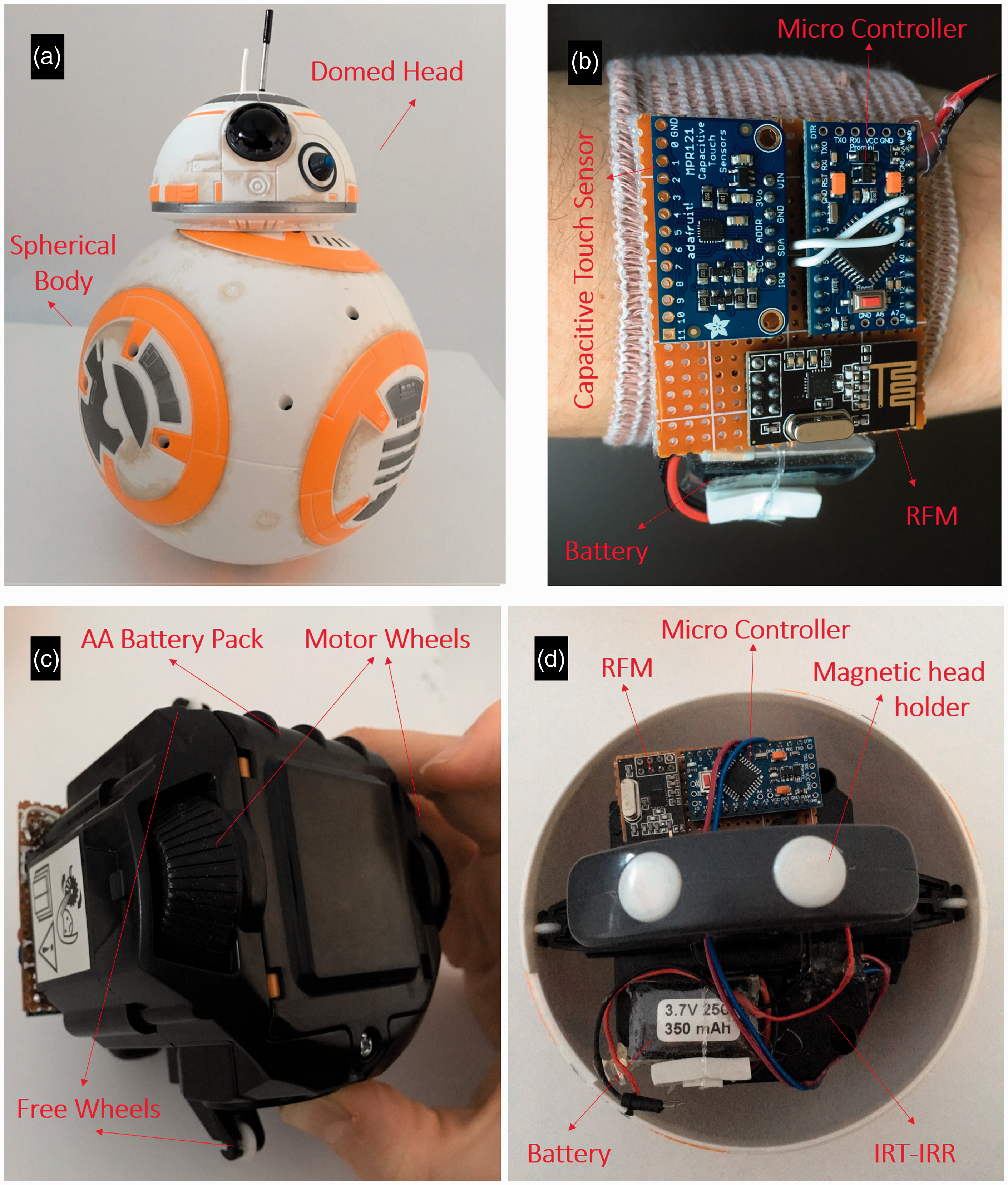
Remote controller of BB8 has two control functions: rotating the BB8’s head and enabling forward movement of BB8 on the direction of its head is pointed. In this study, remote controller of the BB8 is replaced with the conductive yarns which are placed onto a shirt sleeve. Wireless controlling of the movements of BB8 via touching the conductive yarns has been demonstrated successfully. Thus, this study exhibits an interesting and feasible application of conductive yarns in wearable electronics. Similar wearable electronics can be also used to control our mobile phones and other electronic gadgets in similar fashion.
Experimental
Preparation of AgNWs
AgNWs are synthesized according to the modified polyol method [17]. All reagents used in this process were analytical grade and purchased from Sigma Aldrich. Polyvinylpyrrolidone (PVP) (0.5 g) is dissolved in 50 ml ethylene glycol (EG) in a three-necked glass flask at 170℃ for 40 min. The heat was adjusted using a silicon oil bath. After the dissolving process, 150 µl of 1 M NaCl–EG solution is added to the PVP solution. Meanwhile, 0.5 g of AgNO3 is dissolved in 50 ml EG and stirred for 50 min, then slowly added into the PVP solution. After AgNO3 solution is completely added into PVP solution, heating process is stopped, but magnetic stirring is proceeded until the AgNWs solution reaches room temperature. The synthesized AgNWs solution is washed out with acetone for several times and finally centrifuged to precipitate out the AgNWs. To apply the AgNWs onto the spandex yarns, 0.5 g of AgNWs was dissolved in 5 ml of ethyl alcohol (EtOH). This solution was placed in an ultrasonic stirrer for 5 min before drop casting process to ensure the homogenous mixing.
Yarn coating
Commercial spandex yarns (donated by Hyosung) (1640 den (g/9000 m)) were coated with AgNWs solution using the drop casting method. Five-centimeter long yarns were placed between two bars and immobilized from their endpoints, leaving the middle part empty. Synthesized AgNWs (0.5 g) were diluted with 5 ml EtOH and drop casted on 1640 den spandex yarn surface from one end to other end for 1X, 2X, 3X, 4X, and 5X using a Pasteur pipette. AgNW–EtOH (0.20 ml) solution was enough to drop casting these five yarns (15 coating processes). This means 0.0013 g of AgNWs was used for drop casting 5 cm yarn for 1X. Drop-casted yarns were heated in the oven at 50℃ for 30 min to completely remove the EtOH. After this process, 5 cm long conductive yarns were obtained and their resistance was measured using a digital multimeter. Probes were gently contacted to the two ends of the yarn and the resistance value was read from the digital multimeter.
Scanning electron microscope
TESCAN VEGA3 scanning electron microscope was employed to record the SEM images of nonwoven pads. Acceleration voltage was 10 kV and working distance was between 8 mm. Samples were not coated for additional conductive material before the SEM scans.
Laundry test
Laundry test of conductive yarns was measured under two conditions. In the first setup, yarns were immersed in deionized water at room temperature for 30 min. Their resistance per unit length values was measured after drying them for 30 min at 50℃. This process was repeated 5X.
In the second setup, a laundering process was conducted based on the ISO 105-C06 test method. In this method, samples were placed inside the metal beakers of the Linitest machine with 150 ml deionized water, 4 g/l fluorescent-free reference detergent, ECE, and 10 steel balls. Then laundering was conducted at 40 ℃ for 30 min. This process was conducted only 1X.
Data acquisition system
Decoded bit sequences for directional instructions on a BB8 robot on 38 kHz frequency band.

Implementation part
In order to control the BB8 through our smart textile, Adafruit MPR121 capacitive touch sensor module was implemented to the radio frequency transceiver system. This module provides touch sensor capability to every conductive and plated conductive materials in collaboration with calibrating property. Thus, the conductive spandex yarn was integrated to this sensor module. In order to control the BB8 from the conductive yarns, system works in three simple steps:
In the first step, Arduino pro mini microcontroller identifies the touch on conductive spandex yarn and modulates directional data to Nordic Semiconductor 2.4 GHz ISM Band Radio Frequency Transmission module. There are two conductive spandex yarns on the sleeve. One yarn is used for rotating the head of the BB8, while the other yarn is used as forward motion button. Touching the yarn triggers the corresponding command and system proceeds to the second step. This system is placed on a Velcro and placed on the forearm, as shown in Figure 1(b).
In the second step, another microcontroller receives the data on the 2.4 GHZ ISM frequency band and then modulates for the IR transmitter. Based on the touch triggered command, one of the IR signals with the bit sequence given in Table 1 is sent to the infrared receiver of BB8. This system is manually placed on the mechanical core of the BB8, as shown in Figure 1(d).
In the final step, infrared receiver of BB8 receives data in terms of infrared signals on 38 kHz frequency and applies commands that are given by skin touch through its main controller. In order to apply commands, BB8 robot main controller has two motors and each motor has a wheel that is parallel to BB8 robot sphere’s plane as shown in Figure 1(c). These motors are also on the same orientation. In this manner, motors allow to move forward and radial directions. BB8 robot’s head is attached on top of its spherical body with magnetic force.
All of the electronics components and lithium polymer battery were obtained from Robotistan, an online store.
Results and discussion
AgNWs were synthesized according to the polyol method, as explained in the experimental part. SEM images belonging to synthesized AgNWs are shown in Figure 2(a) and (c), and their length and diameter distributions are shown in histogram diagrams in Figure 2(b) and (d), respectively. Average length and diameter of the 50 AgNWs were measured as 13.4 ± 3 and 95.3 ± 42.4 µm, respectively. These average length and diameter values are in good agreement with the previously reported studies [17,18].
SEM image of AgNWs under 5000X magnification (a) and their length distribution is given as a histogram diagram (c). SEM image of AgNWs under 30,000X magnification (b) is used for calculating the AgNW diameter distribution which is plotted as a histogram diagram (d).
After the drop coating process, yarns were dried in the oven to completely evaporate the EtOH. Finally, resistance of these five yarns was measured from both ends and the corresponding data are plotted in Figure 3 (immersion duration is zero). These data clearly indicate that drop casting cycles decrease the resistivity of the yarn. While only 1X drop casting yarn has a resistance value of 1530 Ω/cm, resistance decreases to 12 Ω/cm after 5X drop coating. Increasing the drop casting number increases the number of the AgNWs and provides higher number of connections between AgNWs. This is also confirmed with the SEM images obtained from these five samples. Increasing the drop casting number obviously results in denser AgNW network on the yarns as shown in Figure 4, resulting in a higher conductivity. In addition, SEM images show that AgNW network is very similar for 4X and 5X drop-casted samples, just like their resistance given in Figure 3 (19 and 12 Ω/cm, respectively).
From top to bottom, resistance per unit length (Ω/cm) values of 1X, 2X, 3X, 4X, and 5X drop-casted conductive yarns. Samples were immersed into the deionized water at room temperature for various times. Then resistance per unit length values was measured after drying the samples for 30 min at 50℃. From left to right, SEM images of 1X, 2X, 3X, 4X, and 5X drop-casted spandex yarns under 200X (top) and 3000X (bottom) magnification. Scale bar on the top and bottom images corresponds to 200 and 20 µm, respectively.

After the initial measurements of resistance, yarns were exposed to two types of washing tests. In the first test, conductive yarn samples were immersed in the deionized water, without applying any mechanical force for 30 min and then oven dried for 30 min at 50℃. Holding the yarns in the deionized water results in a decrease in the resistance values of all yarns, except 1X drop casting yarn. As explained in the literature, this is an expected phenomenon in case of AgNWs synthesized via polyol method. In this method, PVP residues around the AgNWs decrease the conductivity. However, PVP is soluble in water. Immersing AgNW-coated yarns into the deionized water dissolves the PVP residues and decreases the resistance of the samples [4,19]. Conductive yarns prepared in this study also follow this path, except only 1X drop-casted yarn. Since this yarn already has very high resistivity (1530 Ω/cm), even a small interruption on the AgNW network results in unrecoverable lost in its conductivity. Immersing other four samples in deionized water does not result in any destructive effect on their conductivity. However, this does not mean that yarns are thoroughly washable.
In the second washing test, which mimics the regular laundry process in a benchtop Linitest machine, yarn samples were washed at 40℃ for 30 min using detergent. As shown in Figure 5, it is apparent from the color of the yarns that laundering process completely removes the AgNWs in some parts even for the 5X drop-casted sample. Thus, all yarns lost their conductivity after the second laundering process. Conductive yarns can be coated with an additional insulating layer which covers the AgNWs coating. This can provide washable conductive yarns. However, in our application, we do not need thoroughly washable yarns because yarns can be demounted from the shirt sleeve before washing the shirt.
Camera images of (a) 5X drop-casted spandex with AgNWs before washing in the Linitest machine (top left), (b) inside the Linitest beaker (right), and (c) after the washing process (bottom left). AgNW: silver nanowire.
As shown in Figure 6(a) and (b), conductive yarns can be implemented on the shirt sleeve. Only a small amount of yarns is visible on the top of the sleeve, which has enough length for touching. Under the sleeve, we created a pocket which can be open to remove or place the conductive yarn inside the sleeve (Figure 6(c)). The wires shown in Figure 6(c) connect the conductive yarns to the electronic touch sensor which is placed on the forearm (Figure 1(b)) and actually remains under the shirt. Thus, the only visible part of the wireless control system is the two conductive fibers on the sleeve, as shown in Figure 6(b).
Sleeve of the shirt (a) with two conductive spandex yarns (b). Conductive yarns are attached to the capacitive touch sensor with copper wires from under the sleeve (c).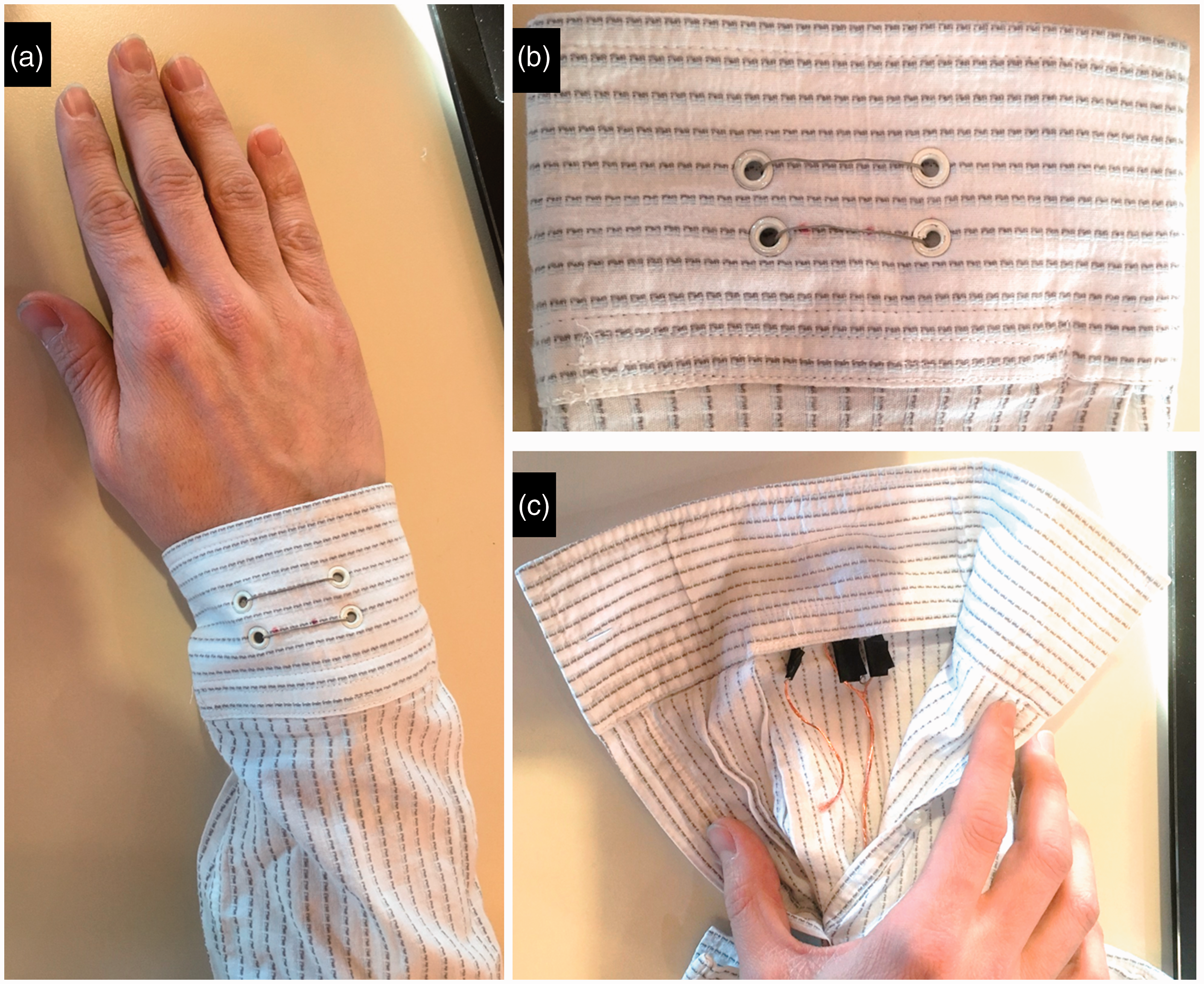
BB8’s remote controller’s directional codes are implemented to a transceiver system as explained in the experimental part. Then conductive yarn probes are connected to an embedded electronic touch sense and receiving system through copper wires. These electronic systems are attached to a Velcro and placed on the forearm as shown in Figure 1(b) and their hardware block diagrams are illustrated in Figure 7. Touching on the conductive yarn with bare hands creates a capacitive variation. This variation digitally interrupts the embedded touch system with respect to the touched conductive yarn. One yarn corresponds to control of radial motion of the BB8’s head, while second yarn controls the forward motion of the spherical body. The system receives commands to be sent and modulates directional data through 2.4 GHz radio frequency ISM band. Another system demodulates incoming radio frequency, demodulated directional data are then modulated to 38 kHz infrared band. Using the decoded bit sequences in Table 1, infrared signal is sent to the BB8 robot system’s IR receiver. After receiving signals, BB8 follows requested directives.
(a) Hardware block diagrams of capacitive touch sensor, (b) radio frequency receiver, and (c) infrared transmitter system. RF: radio frequency.
In this way, identified touch states are successfully transferred to the main robot controller as shown in this video (https://www.youtube.com/watch?v=Jf5KNjcM01Q&feature=youtu.be). BB8 identifies the data by demodulation and then functions motors in a given manner. Just after wheels are moved, there will be instability with respect to gravity. BB8 robot mechanism will move in the desired direction in order to maintain its stable position. Also the head will move along with mechanical core inside the sphere due to the applied magnetic force on each other.
In contrast, and in a better way, designed communication system uses RF communication protocol. This means that our remote system does not have to be looking at the robot. The remote system can also be in another room or far away in many 10 s of meters. This method is an improved way of communication protocol for BB8 robot. In the future, open source products will make these processes simpler and more robust.
Conclusion
In conclusion a conductive spandex yarn has been developed after the drop casting of AgNWs. Increasing the amount of AgNWs results in better conductivity as indicated by the lower resistance of the yarns. These conductive yarns were implemented in a smart wearable electronic application where they were attached to a shirt sleeve for remote controlling a toy robot, BB8. Touching the conductive yarns creates a capacitive variation that is used as directives. These directives were processed in our electronic system on the forearm and then wirelessly transmitted to the BB8 robot system where it demodulates infrared data and follows all requested directives. This application illustrates a wearable electronic example on the frontier of human–machine interface. Similar wearable electronics can also be used to control our mobile phones and other electronic gadgets in similar fashion.
Footnotes
Declaration of conflicting interests
The author(s) declared no potential conflicts of interest with respect to the research, authorship, and/or publication of this article.
Funding
The author(s) disclosed receipt of the following financial support for the research, authorship, and/or publication of this article: This study is funded by European Commission Marie Sklodowska-Curie Actions, Individual Fellowship Program under Grant agreement ID: 739891.