
Abstract
In this research work, the authors have investigated the influence of fibre orientation on thickness and tenacity of needle-punched nonwoven fabrics by using three-factor three-level Box–Behnken Design. Three carding parameters such as feeder speed, cylinder speed and doffer speed, which are primarily responsible for fibre orientation, were considered as three factors with three different levels. Fibre orientation was evaluated in terms of anisotropy by using tracer fibre technique. Anisotropy was measured in both un-punched and punched fibrous structure. Tenacity was measured in both machine and cross directions. It was found that the tenacity in the cross direction and thickness decreases but the tenacity in the machine direction increases with the increase of anisotropy as well as fibre orientation.
Introduction
Nonwoven is a widely used engineered material and also a faster growing sector in technical textile. There are various uses such as medical textile, geotextile, agro textile, industrial air filter and many others. In recent days, the use of air filters is growing at a very faster rate. The nonwovens are very effective for industrial depth filtration application [1]. The comparative study between thermo-bonded and needle-punched nonwoven [2] confirmed that needle-punched nonwoven performs better in terms of filtration efficiency and pressure drop.
The properties of nonwoven depend on fibre type, cross-section, staple length and structural orientation of the constituents fibre [3]. The orientation of the fibres has a big influence on the tensile strength of the nonwoven material. In case of carded web, the fibres are arranged along the machine direction. Thus, tensile strength is higher in the machine direction and is lower across the machine direction [4]. The tensile strength of the parallel web or random web decreased with increasing angle of cut of the specimen for strength measurement. Elongation is higher in the horizontal direction or the cross direction [5–8].
A lot of research work on the influence of card parameters on yarn properties is available. Few researchers [9,10] worked on the effect of cylinder-doffer setting of the card on hook formation, and the influence of drafting direction on U-shaped hook removal, regularity of output sliver, and yarn properties. The majority of fibres change their configuration during transfer. Hooks are formed and formerly formed hooks are removed. Transfer of fibres takes place both with and without reversal of ends. Those fibres that transfer without reversal, change their configurations more [11,12]. Another work of Lawrence et al. [13] proposed hypothesis for the mechanism of fibre transfer in which the trailing ends of fibres are raised from the cylinder surface by centrifugal forces and become hooked around the teeth of the doffer clothing. In the meantime, frictional drag of the doffer clothing removes these fibres from the cylinder clothing. In case of staple fibre spinning, opening of fibre is one of the most important requirements. The yarn, which is properly carded and combed, shows higher strength due to its higher fibre extent and spinning in coefficient. It has been found [14] that increase in fibre openness at carding reduces irregularity and enhances the yarn tenacity but up to a certain limit, after which the results go downwards. Another research group reported that with increase in card draft, and card coiler diameter, the number of leading and trailing hooks reduces. Cylinder speed is another important parameter, which has a large impact on yarn quality due to its effect on fibre orientation [15]. Jabbar et al. [16] studied the relationship between cylinder speed and card production rate with yarn properties. They reported that increase in cylinder speed up to a certain level, yarn irregularities decrease, but also within a boundary beyond that yarn irregularities increases. It has been reported that among all process parameters of spun yarn technology, the carding parameters are the most contributing factor influencing the yarn qualities [17]. There was another finding that speed of cylinder and doffer carding rate increase yarn strength and improve evenness [18]. Similarly, nonwovens are roller carded webs (which are punched) oriented in a particular direction. Therefore, the cylinder and doffer speeds also have intense effect on final nonwoven fabric. The work [19] reported that the thickness decreases and the tenacity in the machine direction increases with the increase of cylinder speeds. However, the work was conducted only with cylinder speed, and the range of speed was limited. In another work, the influence of cylinder speed on the tenacity of needle-punched nonwoven-reinforced bio-composite has been investigated [20]. They found an increasing trend with the increase of cylinder speed. However, no literatures are found regarding the effect of feeder and doffer speed on the properties of nonwoven.
Therefore, there is a requirement of a constructive research about the impact of all three carding parameters like feeder, cylinder and doffer speeds on the fibre orientation and the properties of needle-punched nonwoven. This research work is designed to investigate the influence of the above parameters on the fibre orientation as well as thickness and tenacity. The research work was conducted and analyzed with help of response surface methodology.
Experimental
Materials and sample preparation
The research work was conducted with a 1.5-d, 38-mm staple viscose fibre. A total number of 15 samples were prepared as per the three factors three levels Box–Behnken Design as shown in Table 2. The basis weight of the samples was kept constant (300 ± 10 g/m2).
Experimental designs
The influence of machine parameters on needle-punched nonwoven air filter fabric was carried out for a Box–Behnken design of three process factors, namely feeder speed (A or Х1), cylinder speed (B or Х2) and doffer speed (C or Х3), each being varied at three different levels. The original factors of Х1, Х2, Х3 were coded as given below

Three factors three levels Box–Behnken design and the responses of fibre orientation, thickness and tenacity.

Actual values of variables corresponding to coded values.

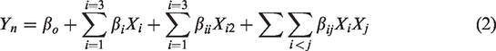
j = 1, 2, 3; n = 1, 2, 3, …
where Yn denotes anisotropy (before punching) (Y1), anisotropy (after punching) (Y2), thickness (Y3), tenacity in the machine direction (Y4), tenacity in the cross direction (Y5), Xi and Xj indicate coded levels of process factors; and βo, βi, βii, βij are the regression coefficients for intercept, linear, quadratic, and interaction terms, respectively. The coefficients of regression were estimated by the method of least squares. The adequacy of the regression model was evaluated in terms of coded factors and significant model.
Evaluation of fibre orientation: Anisotropy
Fibre orientation was measured in terms of fibre inclination angle with a respective direction of fabric with the help of tracer fibre technique. Samples were prepared with 0.3% red colour tracer fibre. Alpha-methyl-styrene was used as an optical dissolving liquid as discussed by Roy et al. [21]. Three thousand readings of fibre inclination angle were grouped into 12 class intervals of equal range, i.e. 15° (0.26 rad). Accordingly, the frequency distribution of inclination angle of the fibre was obtained. The histogram of fibre inclination angle in the machine direction is obtained using the mathematical model [22]

SEM image of fibre orientation (anisotropy behaviour) with different carding parameters. (a) Feeder: 0.18 m/min, cylinder: 100 m/min, doffer: 4 m/min. (b) Feeder: 0.15 m/min, cylinder: 250 m/min, doffer: 5.5 m/min.
Evaluation of other properties
Basis weight
The test was done according to the standard ASTM D5261-10. Small square-shaped samples of 100 mm × 100 mm were cut from all the original fabric samples. Then the weight of each sample was taken in a calibrated electronic balance which ranged from 0.05 g to 6400 g with an accuracy of 0.01 g. An average of 10 tests was taken into consideration.
Thickness
The thickness of the fabrics was measured according to ASTM D1777-96 (2007) standard with the Essdiel thickness gauge at a pressure of 1.1 kPa. Small square-shaped samples of 100 mm × 100 mm were cut from all the original fabric samples. The compression time was 60 s. An average of 10 tests was taken into consideration.
Tensile strength
ZWICK/ROELL Z100 was used to measure breaking force and elongation in both machine and cross directions as per ASTM D 5035. An average of five tests was taken into consideration.
Results and discussion
Fibre orientation: Anisotropy (before punching)
Table 3 gives an account of the significance of the influence of carding parameters on the fibre orientation on anisotropy (before punching). The linear effects of cylinder speed, doffer speed and feeder speed were highly significant with p-values 0.0002, 0.0001 and 0.0005, respectively, on anisotropy (before punching).
Variance analysis of anisotropy of before punching.

The response surface equations for anisotropy in terms of coded factors and significant model terms are represented in equations (4)
The 3D surface plots of cylinder speed and feeder speed at constant doffer speeds before punching are shown in Figure 2(a). The value of anisotropy increases with the increase of cylinder speed and decreases as feeder speed increases at the respective doffer speed. The increase of both feeder and cylinder speeds at different doffer speeds show an increasing trend of anisotropy but the increase of doffer speed further enhances the value of anisotropy. The value of anisotropy depicts an increasing trend with the increase of all considered card parameters.

Influence of carding parameters on anisotropy in before punching stage. (a) Doffer speed: 5.5 m/min. (b) Cylinder speed: 175 m/min. (c) Feeder speed: 0.18 m/min.
Figure 2(b) shows an increase in the value of anisotropy with the increase of doffer speed and a reduction with the increase of feeder speed at the respective cylinder speed. With the increase of both feeder and doffer speeds, the anisotropy initially decreases towards lower cylinder speeds and then increases towards higher cylinder speeds.But the increase of cylinder speed continuously increases the value of anisotropy with different combinations of feeder and doffer speeds. The increase of feeder, cylinder and doffer speeds further increases the value of anisotropy.
The 3D surface plots of the cylinder and doffer speed at the respective feeder speeds before punching are shown in Figure 2(c). The value of anisotropy increases with the increase of cylinder and doffer at the respective feeder speed. The increase of both doffer and cylinder speeds at different feeder speeds shows an increasing trend of anisotropy but the increase in feeder speed reduces the value of anisotropy. The value of anisotropy depicts an increasing trend with the increase of considered card parameters.
The cards process parameters are optimized for the minimum value of anisotropy using equation (2). A combination of 0.209 m/min feeder speed, 101.46 m/min cylinder speed and 4.630 m/min doffer speed gives 2.60 anisotropy.
The value of anisotropy before punching increases with the increase of cylinder and doffer speeds but decreases with the increases in feeder speed as shown in Figure 2(a) to (c). The displacement of fibre from the axis of web reduces with the increase of cylinder and doffer speeds but the displacement of fibre increases with the increase of feeder speed due to higher fibre loading on the surface of the cylinder. Higher loading of fibres on cylinder reduces the fibre opening and individualization action.
But the value of anisotropy follows an increasing trend with the increase of feeder, cylinder and doffer speeds. The results retained the domination of cylinder and doffer speeds over feeder speed to enhance the anisotropy.
Anisotropy (after punching)
Table 4 gives an account of the significance of the influence of carding parameters on the fibre orientation on the anisotropy of after punching. The linear effects of cylinder speed, doffer speed and feeder speed were highly significant with p-values 0.0001, 0.0001 and 0.0001, respectively, on proportion of curved fibre ends.
Variance analysis of anisotropy after punching.

The response surface equations for anisotropy of after punching in terms of coded factors and significant model terms are represented in equations (5)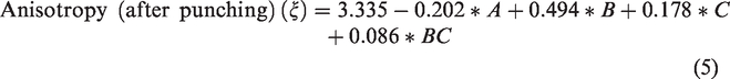
The 3D surface plots of cylinder speed and feeder speed at the respective doffer speed of Figure 3(a) after punching show an identical trend as observed for before punching but have lower values of anisotropy.

Influence of carding parameters on anisotropy in after punching stage. (a) Doffer speed: 5.5 m/min. (b) Cylinder speed: 175 m/min. (c) Feeder speed: 0.18 m/min.
The 3D surface plots of doffer speed and feeder speed at constant cylinder speed after punching are shown in Figure 3(b). The obtained results are identical to the results of before punching but with a lower value of anisotropy.
Figure 3(c) shows the 3D surface plots of doffer and cylinder speeds at constant feeder speed after punching. The obtained results of before and after punching are found to be identical but depict the lower value of anisotropy in comparison to before punching.
The optimized minimum value of 2.30 anisotropy after punching is obtained from equation (5) at a combination of 0.21 m/min feeder speed, 100 m/min cylinder speed and 5.5 m/min doffer speed.
The value of anisotropy after punching increases with the increase of cylinder speed and doffer speed but decreases with the increase of feeder speed as shown in Figure 3. The observed trend follows an almost similar trend of anisotropy as noticed in case of the layered fibrous web (before punching). However, punching action as discussed above reduces the value of anisotropy.
Fabric thickness
Table 5 gives an account of the significance of the influence of carding parameters on the fibre orientation on the fabric thickness. The linear effects of cylinder speed and doffer speed were highly significant and feeder speed was insignificant with p-values 0.1755, 0.0049 and 0.0053, respectively, on fabric thickness.
Variance analysis of fabric thickness.

The response surface equations for fabric thickness in terms of coded factors and significant model terms are represented in equations (6)
Figure 4(a) shows the 3D surface plots of cylinder and feeder speed at different doffer speeds. The fabric thickness decreases with the increase of cylinder speed but increases with the increase of feeder speed at the respective doffer speed. The results of fabric thickness show a decreasing trend with the increase of both feeder and cylinder speeds at 4.0 m/min doffer speed. The doffer speeds of 5.5 and 7.0 m/min show an initial increase and then a decrease in fabric thickness with the increase of both feeder and doffer speeds. But the fabric thickness shows a decreasing trend with the increase of feeder, cylinder and doffer speeds.

Influence of carding parameters on fabric thickness. (a) Doffer speed: 5.5 m/min. (b) Cylinder speed: 175 m/min. (c) Feeder speed: 0.18 m/min.
The 3D surface plots of doffer and feeder speeds at the constant cylinder speed of Figure 4(b) depict the decrease of fabric thickness with the increase of doffer speed but fabric thickness increases with the increase of feeder speed at the respective cylinder speed. The increase of both feeder and doffer speeds at 100 and 175 m/min cylinder speeds reduces the fabric thickness but 250 m/min cylinder speed depicts the increasing trend of fabric thickness. But the increase of feeder, cylinder and doffer speeds reduces the fabric thickness.
Figure 4(c) shows a reduction in fabric thickness with the increase of doffer and cylinder speeds at a constant feeder speed. The increase of cylinder as well as doffer speed at respective feeder speed reduces fabric thickness. The fabric thickness continuously decreases and slightly increases at 0.15 and 0.18 m/min feeder speeds but continuously decreases at 0.21 feeder speed with the increase of both cylinder and doffer speeds. But the increase of feeder, cylinder and doffer speeds show a reduction in the fabric thickness.
Equation (6) is used to minimize the fabric thickness. A 0.208 m/min feeder speed, 245.542 m/min cylinder speed and 6.982 m/min doffer speed gives the minimum value of 2.842 mm fabric thickness.
As shown in Figure 4(a) to (c), fabric thickness decreases as cylinder and doffer speeds increase but increases with the increase of feeder speed. The decrease in fabric thickness is mainly due to improved fibres orientation as explained above. Higher cylinder and doffer speeds lead to increase in the coefficient of relative fibre parallelization but reduce the proportion of curved fibre ends. This is responsible for fibre straightening and parallelization as well as a reduction in the number of hooks towards machine direction which ultimately increases fibre extent. On the other hand, with the increase of feeder speed, the fibres get misaligned towards the axis of machine direction which also increases fibre inclination angle and reduces the isotropy resulting in higher fabric thickness. But the results depict the reduction in the fabric thickness with the increase of feeder, cylinder and doffer speeds. It shows that feeder speed could not influence the overall fabric thickness.
A structure properties relationship is established by using nonlinear regression analysis as shown in equation (7)
Fabric tenacity in the machine direction
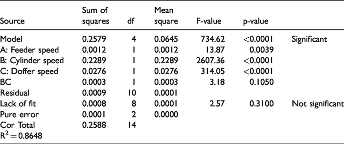
Table 6 gives an account of the significance of the influence of carding parameters on the fibre orientation on the tenacity in the machine direction. The linear effects of cylinder speed and feeder speed were highly significant but doffer speed was less significant with p-values 0.0001, 0.0001 and 0.0462, respectively, on fabric tenacity in the machine direction.
Variance analysis of fabric tenacity in the machine direction.

The response surface equations for fabric tenacity in the machine direction in terms of coded factors and significant model terms are represented in equations (8)
The 3D surface plots of cylinder speed and feeder speed at a constant doffer speed in the machine direction are given in Figure 5(a). The results of fabric tenacity show an increasing trend with the increase of cylinder speed but a decreasing trend with the increase of feeder speed at the respective doffer speed. The results confirm the reduction in fabric tenacity at 4 m/min doffer speed but an increase at 5.5 and 7.0 m/min doffer speeds with the increase of both feeder and cylinder speeds. But with the increase of doffer speed, the fabric tenacity initially increases and then decreases. The increase of feeder, cylinder and doffer speeds increase the fabric tenacity.
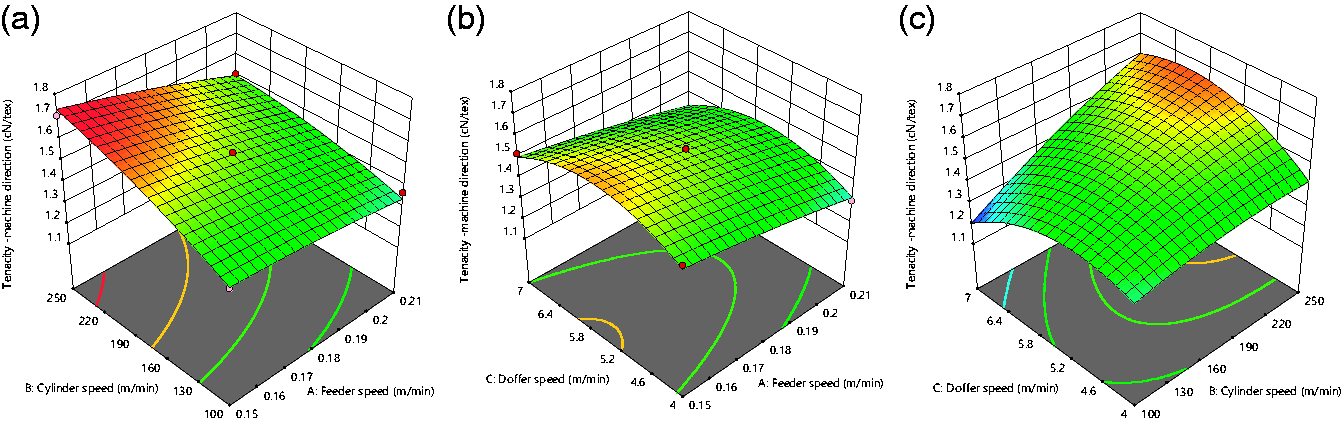
Influence of carding parameters on fabric tenacity in the machine direction. (a) Doffer speed: 5.5 m/min. (b) Cylinder speed: 175 m/min. (c) Feeder speed: 0.18 m/min.
The 3D surface plots of doffer speed and feeder speed at the constant cylinder speed of fabric tenacity in the machine direction are given in Figure 5(b). An initial increase and then decrease in fabric tenacity are noticed with the increase of doffer speed but tenacity reduces with the increase of feeder speed at a respective cylinder speed. The increase of both doffer and feeder speeds shows an initially increasing and then decreasing trend at the respective cylinder speed. But fabric tenacity notices an increasing trend with the increase of cylinder speed. The increase of feeder, cylinder and doffer speeds increases the fabric tenacity.
Figure 5(c) shows the 3D surface plots of doffer speed and cylinder speed at constant feeder speeds of fabric tenacity in the machine direction. Fabric tenacity increases and then decreases with the increase of doffer speed but continuously increases with the increase of cylinder speed at the respective feeder speeds. The fabric tenacity notices an increase with the increase of both doffer and cylinder speeds at a constant feeder speed but it reduces with the increase of feeder speed. The fabric tenacity shows an increasing trend with the increase of feeder, cylinder and doffer speeds.
A combination of 0.157 m/min feeder speed, 247.495 m/min cylinder speed and 6.38 m/min doffer speed provides an optimized maximum value 0.171 cN/tex for fabric tenacity in the machine direction using equation (8).
It is observed from the response surface plots 5(a) to (c) that the tensile strength of nonwoven fabric in the machine direction increases with the increase in the cylinder and doffer speeds but decreases with the increase in feeder speed. The results have already established the increase of fabric tenacity with the increase of the feeder, cylinder and doffer speeds. The increase of coefficient of relative fibre parallelization, the coefficient of fibre curliness and anisotropy and a decrease of the proportion of curved fibre ends and fibre coverage area with the increase of feeder, cylinder and doffer speeds are responsible for the increase of fabric strength in the machine direction.
A structure properties relationship is established by using nonlinear regression analysis as shown in equation (9)
Tenacity in the cross direction
Table 7 gives an account of the significance of the influence of carding parameters on the fibre orientation on the tenacity in the cross direction. The linear effects of cylinder speed and doffer speed were highly significant but feeder speed was less significant with p-values 0.0039, 0.0001 and 0.0001, respectively, on fabric tenacity in the machine direction.
Variance analysis of fabric tenacity in the cross direction.
The response surface equations for fabric tenacity in terms of coded factors and significant model terms are represented in equations (10)
Figure 6(a) shows that the fabric tenacity in the cross direction decreases with the increase of cylinder speed but increases with the increase of feeder speed at the respective doffer speed. The increase of both cylinder and feeder speeds at the respective doffer speed reduces the fabric tenacity but the increase of doffer speed further reduces the fabric tenacity. The results confirm a reduction in fabric tenacity with the increase of all three card variables.

Influence of carding parameters on tenacity in the cross direction. (a) Doffer speed: 5.5 m/min. (b) Cylinder speed: 175 m/min. (c) Feeder speed: 0.18 m/min.
The results of Figure 6(b) show a reduction in fabric tenacity in the cross direction with the increase of doffer speed but an increase with the increase of feeder speed at the respective cylinder speed. Fabric tenacity decreases with the increase of both feeder and doffer speeds at the respective cylinder speed but further reduction is noticed with the increase of cylinder speed. The increase of feeder, cylinder and doffer speeds reduces the fabric tenacity.
Figure 6(c) shows the 3D surface plots of doffer speed and cylinder speed at constant feeder speeds of fabric tenacity in the cross direction. The fabric tenacity shows a reducing trend with the increase of doffer and cylinder speeds at the respective feeder speed. The increase in both cylinder and doffer speeds at the respective feeder speed reduces the fabric tenacity but the increase of feeder speed shows an increasing trend. The fabric tenacity depicts a reduction with the increase of feeder, cylinder and doffer speeds.
Equation (10) of fabric tenacity in the cross direction at a combination of 0.196 m/min feeder speed, 101.740 m/min cylinder speed and 4.232 m/min doffer speed gives an optimized maximum value 0.092 cN/tex fabric tenacity in the cross direction.
A structure properties relationship is established by using nonlinear regression analysis as shown in equation (11)
Overall optimization
The carding was optimized for achieving the required characteristics of filter media. The required goals are illustrated in Table 8. In the optimization process, three carding parameters were optimized. Equal emphasis was given to all the three mentioned properties.
Constraints for the optimization process.

The optimized carding parameters and the obtained values of nonwoven properties are given in Table 9.
Optimized carding parameters and the values of the properties.

Conclusions
From the above discussion, it can be concluded that the carding parameters (feeder, cylinder and doffer speeds) influenced the fibre orientation and the properties like thickness and tensile strength. Higher feeder speeds imparted disorientation in the structure as a result of the thickness increases and the tenacity decreases in the machine direction whereas increases in the cross direction. One the other hand, the fibre orientation in the machine direction increased initially and decreased in a later stage with the increase of cylinder and doffer speeds. Therefore, the cylinder and doffer speeds initially decreased the thickness then increased slightly, whereas in case of tenacity, opposite trend of thickness was observed. The maximum tenacity and minimum thickness were obtained at 0.15 m/min feeder speed, 165.879 m/min cylinder speed and 5.79 m/min doffer speed.
Footnotes
Declaration of conflicting interests
The author(s) declared no potential conflicts of interest with respect to the research, authorship, and/or publication of this article.
Funding
The author(s) received no financial support for the research, authorship, and/or publication of this article.