
Abstract
Fresh and pollution-free air is very much required to breathe normal and healthy life. However, due rise in the usage of automobiles and industrialization, the pollution load is also increasing day by day. Hence efficient filter media is in high demand. In this research, a systematic study was planned and executed for the development of efficient and bio-degradable filter media. A total of five process parameters; carding parameters namely, feeder speed, cylinder speed, and doffer speed, and punching parameters namely punch density and depth of penetration were considered as input parameters were considered and their effect on the physical and functional properties of the final fabric were studied. Forty-six samples were prepared as per 5 factor-3 level Box and Behnken design. The properties such as fabric thickness, tenacity, air permeability, and filtration efficiency were evaluated. Finally, the carding and punching parameters were optimized for achieving the required characteristics of filter media and achieving the best performance.
Introduction
Fresh and pollution-free air is highly required of human beings or any other living beings for their good health. 1 Industrialization and high use of personal vehicles, increasing the generation of Nitrogen Dioxide (NO2), Carbon mono-oxide (CO), and ambient particulate matter (fine particulate matter (PM2.5) and larger particulate matter (PM10)), etc.2,3 These are the major contributors to air pollutants. A recent study from the satellite data and different air quality station centers across the globe found that there is a reduction of 29% NO2, 9% reduction PM2.5 with just 15 days lockdown during Covid-19 times.4,5 Further, the ambient particulate matter could play a big role in serious health issues like cardiopulmonary diseases, lung cancer, and mortality.6–8 A statistic published by Sannigrahi et al., 3 with the reduction of pollution load (NO2, PM2.5, and PM10) during Covid-19 lockdown, premature death of 1310, 401, 430 were avoided. People will come to their normal life very soon by beating the Covid-19, and the curve of pollution level takes its peak again. 9 Hence, the use of an efficient filtration system is the only way to fulfill the demand for air free from particulate matter. There are many types of filters are available in the market.10,11 However, the use of needle-punched nonwoven is found most efficient than any other filtration system available in the market.12,13 To meet the sudden surge in demand of efficient air filter, researchers from academia and industry are working very hard to introduce the best needle-punched air filter in the market. They are working on each and every possible aspect, for example, use of different raw materials, changing process parameters and the structural parameters to obtain the best air filter. For example, Umezu and Mizui 14 developed an improved needle-punched structure for the inlet layer to make an efficient air filter for the car engine. Haskett 15 developed a needle punched structure with electret fiber to develop filer media with enhanced life, low-pressure drop and high filtration efficacy. Kothari et al. 16 reported a needle punched structure with improved filtration efficacy and other related properties namely dimensional stability, air permeability, compression-recovery, tensile strength, abrasion resistance and friction by using finer and thicker fiber in 50:50 ratio and changing punch density. In a similar way, Zang et al. 17 presented air filter with high filtration efficiency, and large dust holding capacity using needle-punched electret air filter. Wang et al. have developed further improved filter media of needle-punched triboelectric air filter with silica-modified polytetrafluoroethylene fibers and polyphenylene sulfide fibers. This unique needle-punched nonwoven structure can be charged online without any additional energy and emission of toxic ozone gas. Charge generation would happen during carding and needle punching process due to the presence of triboelectrification effect, this intern resulted in higher filtration efficacy. Like other non-woven manufacturing techniques, needle-punched non-woven fabric is also prepared directly from the fiber. Due to the repeated mechanical action of needle barbs, some fibers in a fibrous carded web redistributed from horizontal to the vertical direction, and fibers got bonded mechanically through fiber entanglement.18,19 The Needle-punched non-woven fabric manufacturing process is a two-step process; fibrous web preparation and punching.20,21 The properties of needle-punched nonwoven fabrics are reliant on various factors. Fiber-related, carding parameters, layering sequence, and needle punching-related parameters are the main dependent factors.22,23 Fiber is the building block of needle-punched fabric. Hence fiber properties like types of fiber (Cotton, Viscose, Polyester, Polypropylene, etc.), fiber length, diameter, cross-section, and blend proportion are the main influencing factor.24,25 Like staple spinning system, carding process is also heart here in needle punched non-woven fabric. Better the carding operation more uniform is the fiber orientation.26,27 Carding operation is the combination of feed roller speed, cylinder rpm, doffer rpm are the major influencing factor from carding action.28,29 The layering sequence and number of the layer will decide the GSM of the fabric. 30 And lastly, punching parameters like needle size, shape, depth of penetration, needle density on needle board, etc. are different parameters to influence the needle punched fabric properties.28,31,32 The needle-punched nonwoven contains periodicity due to the carded webs of having its natural non-uniformity, and inevitably and undesirably creation of pores due to repeated mechanical action of needle barbs. The surface of the needle-punched fabric has visible needle marking, and these holes are in series appear on the fabric surface running through the machine direction. 33 Also, due to the presence of such holes, compromise in terms of the integrity of the needle felt, inferior filtration efficiency, the overall strength of the resultant fabric. Therefore, few drawbacks of needle-punched nonwoven filters are higher basis weight (GSM) and high volumetric density to obtain required optimum strength and uniform filtration efficiencies. Sometimes some extra processes like frequently glaze singeing, calendaring, and coating on the surface, etc. are required to boost filtration efficiency. 34 Sometimes researchers are using reinforcement layers of low GSM other fabrics (woven or spun-bond) to amplify the functional properties namely filtration efficiency, compactness, dimension stability, and mechanical robustness. 35 Recently researchers are using Sheath/Core Low Melting staple fiber along with normal synthetic to improve the tensile strength of needle punched filter fabric. 36
So, there is always some uncertainty of obtained properties and performance level. Hence prediction of required properties and performance level against the input parameters (fiber related, and process parameters) could be beneficial to reduce the number of experiments. Recently researchers are using different prediction tools like empirical models (using multiple regression analysis) and artificial neural networks (ANN) etc. And almost all the researchers concluded that models developed by using ANN are more robust and accurate than any other model.37–39
Over the last few decades, researchers are constantly trying their level best to make the needle punch nonwoven filter more efficient. They are using various fiber types individually or in blends, they also playing with different process parameters like carding and punching parameters based on their experience or taking the help of tools like ANN.40–42 However, as per reported literature, people worked with some selective process parameters. Like Roy et al. 28 considered three carding parameters for example feeder speed, cylinder speed and doffer speed as influencing parameters, Rawal and Anandjiwala 43 studied the effect of feed rate, stroke frequency, and depth of needle penetration on the needle punched fabrics, whereas Dixit et al. 44 found sequential punching found to be beneficial. Although, a lot of reported literature available dealing to improve the overall performance of the needle-punched fabric. But as of now, no literature found that is dealing with all the carding parameters (feed rate, cylinder speed, and doffer speed) and punching parameters (punch density and depth of penetration) together. This is most interesting to understand how all five parameters affect the overall properties. In this research, a systematic study has been carried out to understand the effect of all five parameters on the final needle punched fabric. Moreover, another approach of this research was to develop bio-compostable filter media by using 100% viscose fiber as fibrous raw material to address the end-of-life issue of the filter.
Experimental
Materials and sample preparation
Actual values of variables corresponding to coded values.

Variance analysis of anisotropy.

Figure 1 presents Scanning Electron Microscope monographs of needle-punched nonwoven made of different process parameters. Scanning Electron Microscope image, (a) Feeder speed-0.18, Cylinder speed-250, Doffer speed-4, Punch density-150, Needle penetration depth – 8, (b) Feeder speed-0.15, Cylinder speed-175, Doffer speed-5.5, Punch density-100, Needle penetration depth – 8.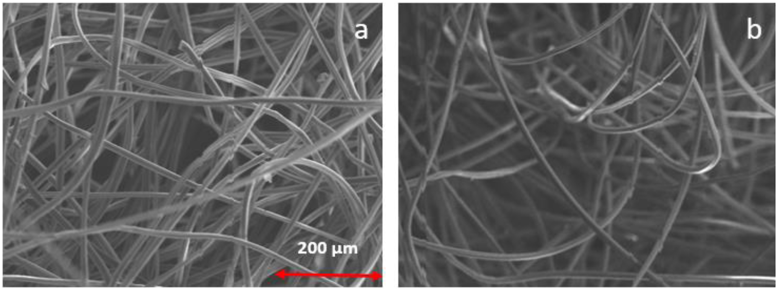
Evaluation of fibre orientation: Anisotropy
The fibre inclination angle is a measure of the angle in radian at an interval of 1.0 mm segments of fibre in the machine direction. The mean value of these angles is defined as the fibre inclination angle (F
ia
) as indicated in Figure 2(a) schematic view of fiber angle measurement and (b) histogram of angles. For measuring the angle of fibre inclination around 350 fibres were considered. Evaluation of anisotropy, (a) schematic view of fibre angle measurement, (b) histogram of angles.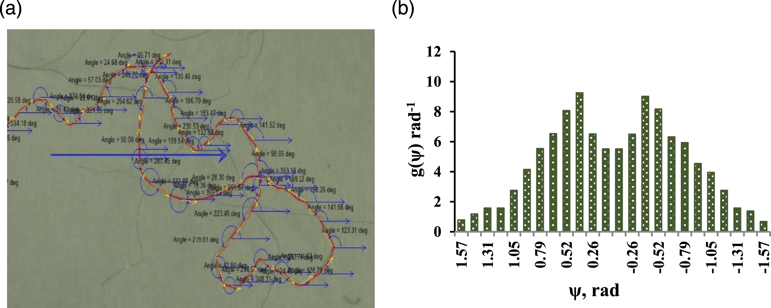
Every measurement of fibre inclination angle was been allotted into 24 class intervals of equivalent range i.e. 7.5°(0.13 radian). As a result, the frequency distribution of the inclination angle of the fibre was obtained. The anisotropy of the angle of fibre inclination in the carding direction was calculated employing the mathematical model as proposed by Neckář et al.
18
As shown in Figure 2(b) g(Ψ) is the probability density function of all measured angles Ψ and the measure of anisotropy of fibre orientation in fibre web are denoted by η. The value of parameter n was calculated for each web. The value of anisotropy from equation (1).
Evaluation of mechanical and functional properties
The thickness of the fabrics was measured according to the ASTM D1777 standard with the Essdiel thickness gauge at a pressure of 1.1 kPa. An average of 10 test data was taken into consideration. Tensile strength was measure in both machine and cross directions by using ZWICK/Roell Z100 as per ASTM D5035. An average of 10 test data was taken into consideration in each direction. On the other hand, the Air permeability of the fabric was measured using Textest FX 3300 air permeability tester at a pressure of 125 Pa as per BS 5636. A sample size of 10 was considered for air permeability measurement. Lastly, the filtration efficiency and pressure drop of the nonwoven fabrics were measured according to ISO/TS 11155-1 by employing, a purpose-built air filtration set-up. 12
Results and discussions
Anisotropy
The variance analysis of anisotropy is shown in Table 2. The obtained 2FI model was found to be significant. The linear effect of feeder, cylinder, and doffer speed, punching density, and needle penetration depth, along with the square of cylinder speed and its interactive effect with feeder and doffer speed was registered as highly significant, with of p-value < .0001. The interactive effect of the feeder with punch density and the interaction of cylinder with doffer, punch density, and needle penetration depth and the interactive effect of doffer and punch density were found significant.
The anisotropy, in terms of coded factors and significant model terms, is represented in the response surface equation (2). Very strong correlation was observed between anisotropy and carding and punching parameters, with a R2 value of 0.97.
The 3D surface plots of needle penetration depth versus punch density, at three different feeder speeds at the constant cylinder and doffer speeds, are shown in Figure 3. The anisotropy depicted a decrease with the increase in both needle penetration depth and punch density, at the respective feeder speed, but a reduction with the increase in feeder speed. The increase in feeder speed, needle penetration depth, and punched density, at the constant cylinder and doffer speeds depicted a decreasing trend of anisotropy. Anisotropy – needle penetration depth versus punch density, at different feeder speeds but constant cylinder and doffer speeds.
Figure 4 presents the 3D surface plots of needle penetration depth versus punch density, at three different cylinder speeds, but at constant feeder and doffer speeds. The anisotropy inferred a decreasing trend while increasing both punching parameters, at the respective cylinder speed. But a continuous increase was observed with the increase in cylinder speed. The anisotropy showed a decrease with the increase in cylinder speed, needle penetration depth, and punched density, keeping feeder and doffer speeds constant. Anisotropy – needle penetration depth versus punch density, at different cylinder speeds but constant feeder and doffer speeds. (a)Feeder- 0.18 m/min, Cylinder- 100 m/min, Doffer- 5.5 m/min. (b)Feeder- 0.18 m/min, Cylinder- 175 m/min, Doffer- 5.5 m/min. (c)Feeder- 0.18 m/min, Cylinder- 250 m/min, Doffer- 5.5 m/min.
The 3D surface plots of needle penetration depth versus punch density, at three different doffer speeds, but at constant feeder and cylinder speeds are represented in Figure 5. A continuous decrease in anisotropy was observed, with the increase in both punching parameters, at respective doffer speed. But the increase in doffer speed showed a continuous increase in anisotropy. A reduction in anisotropy was noticed with the increase in doffer speed and both punching parameters, keeping feeder and cylinder speeds constant. Anisotropy – needle penetration depth versus punch density, at different doffer speeds but constant feeder and cylinder speeds.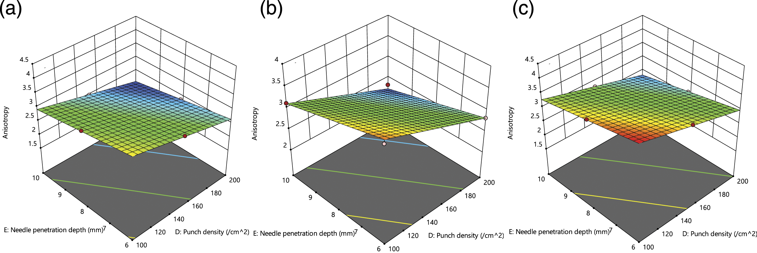
Figure 6 shows the 3D surface plots of needle penetration depth versus punch density, at three different feeder, cylinder, and doffer speeds. A decreasing trend of anisotropy observed with the increase in both punching parameters, at the respective feeder, cylinder and doffer speeds. But a continuous increase was noticed, with the increase in all three carding parameters. Further, a reduction in anisotropy was noticed with the increase in both carding and punching parameters. Anisotropy – needle penetration depth versus punch density, at different feeder, cylinder and doffer speeds.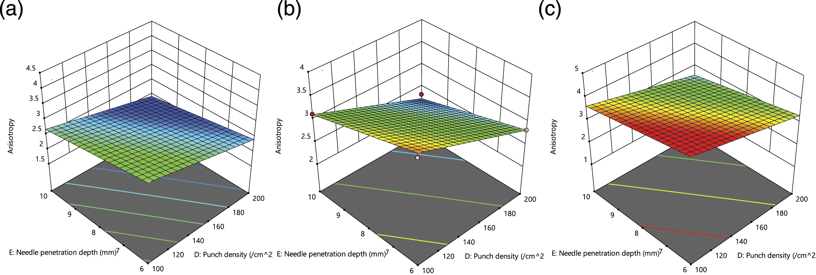
Higher feeder speed resulted in less opening of fibre, therefore, more number of fibres were found in random direction, as a result of which the value of anisotropy decreases. The increase of punch density and penetration depth showed a decreasing trend in anisotropy because of spreading of fibres in cross direction. Higher cylinder and doffer speeds ensured better fibre opening, therefore, less fibre curling was found in fibres and, as a result, anisotropy increased. From the above discussion, it is observed that higher feeder speed decreased anisotropy, whereas both cylinder and doffer depicted an opposite effect. The resultant effect of the increase of all three carding parameters increased the anisotropy and clearly confirmed the domination of cylinder and doffer speed, over the feeder speed. The anisotropy continuously decreased with the increase of both punch density and needle penetration depth. The above trends is supported by the work of Roy and Ishtiaque.17,31
The maximum 3.941 anisotropy was achieved, at a combination of 0.157 m/min feeder speed, 249.680 m/min cylinder speed, 6.349 m/min doffer speed, 129.851 punch/cm2 and 7.185 mm needle penetration depth, using equation (2).
Fabric thickness
Variance analysis of fabric thickness.

The response surface equation for fabric thickness, in terms of coded factors and significant model terms, is represented in equation (3). Very strong correlation was observed between fabric thickness and carding and punching parameters, with a R2 value 0.912.
The 3D surface plots of needle penetration depth versus punch density, at three different feeder speeds, but at constant cylinder and doffer speeds are shown Figure 7. The fabric thickness depicted a decrease with the increase in both punching parameters, at respective feeder speed. But the fabric thickness noticed an increase with the increase in feeder speed, at lower levels of punching parameters, but towards higher level of punching parameters a decreasing trend was observed. The decreasing trend of fabric thickness was inferred with the increase in feeder speed and both punching parameters, at constant cylinder and doffer speeds. Fabric thickness – needle penetration depth versus punch density, at different feeder speeds but constant cylinder and doffer speeds.
Figure 8 presents the 3D surface plots of needle penetration depth versus punch density, at three different cylinder speeds, but at constant feeder and doffer speeds. A reduction in fabric thickness was observed while increasing both punching parameters, at the respective cylinder speed and also a reduction with the increase in cylinder speed. The fabric thickness depicted a reduction with the increase in cylinder speed and both punching parameters, keeping feeder and doffer speeds constant. Fabric thickness – needle penetration depth versus punch density, at different cylinder speeds but constant feeder and doffer speeds.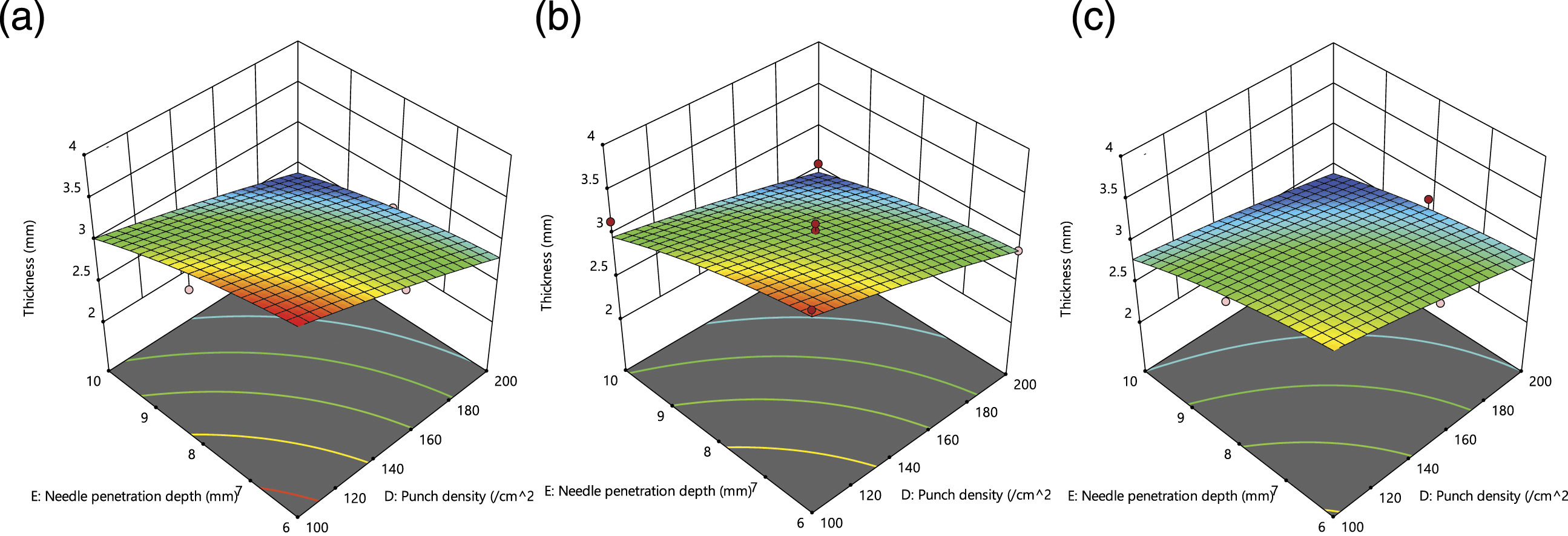
Figure 9 provides the 3D surface plots of needle penetration depth versus punch density, at three different doffer speeds, but at constant feeder and cylinder speeds. The fabric thickness noticed a decrease with the increase in both punching parameters, at the respective doffer speed. But an initial increase was observed with the increase in doffer speed, at lower level of punching parameters and a decrease at higher level of punching parameters. A decrease in fabric thickness was inferred with the increase in doffer speed and both punching parameters, keeping feeder and cylinder speeds constant. Fabric thickness – needle penetration depth versus punch density, at different doffer speeds but constant feeder and cylinder speeds.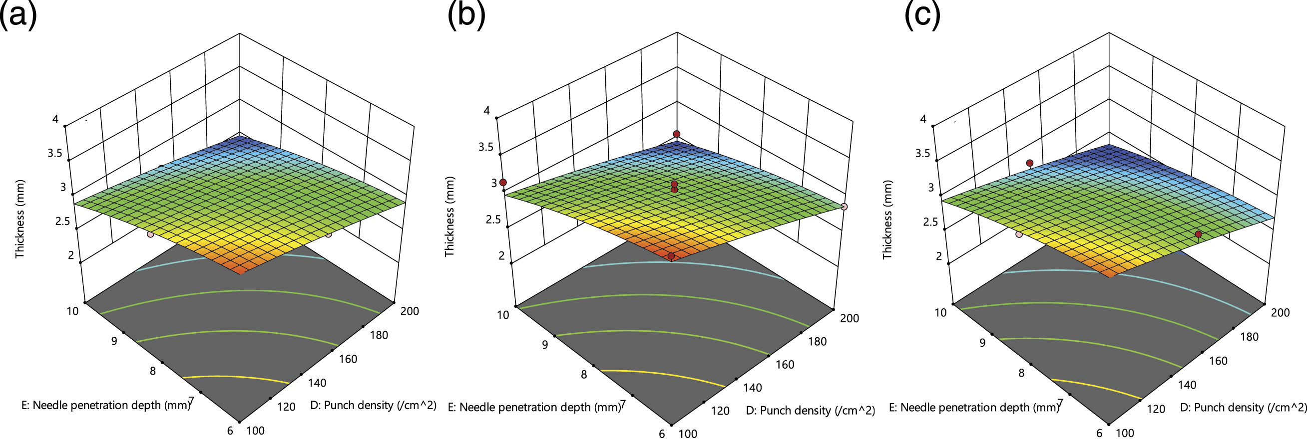
The 3D surface plots of needle penetration depth versus punch density, at three different feeder, cylinder, and doffer speeds are given in Figure 10. The fabric thickness noticed a reduction with the increase in both punching parameters at respective feeder, cylinder and doffer speeds. But an initial decrease and, then, increase in fabric thickness was observed with the increase in feeder, cylinder and doffer speeds, but towards higher value of punching parameters a decrease was noticed. A decreasing trend in the fabric thickness was noticed with the increase in both carding and punching parameters. Fabric thickness – needle penetration depth versus punch density, at different feeder, cylinder and doffer speeds.
Higher feeder speed resulted in less parallelization of fibre, therefore, reducing chances of them getting closer to each other and, as a result, the fabric thickness increased. On the other hand, the higher cylinder and doffer speeds offered better fibre opening, fibres got straighter, parallel and drew closer to each other and, as a result, fabric thickness decreased. The resultant effect of the increase of all three carding parameters initially decreased and, then, increased the fabric thickness. This confirmed the domination of cylinder and doffer over the feeder speed, at lower punching stage. The value of fabric thickness continuously decreased with the increase of both punch density and needle penetration depth. The obtained trends are supported by the work of Roy and Ishtiaque. 23
The carding and punching parameters are optimised for the minimum value of fabric thickness, by using the equation (3). A combination of 0.178 m/min feeder speed, 198.539 m/min cylinder speed, 6.968 m/min doffer speed, 176.712 punch/cm2 and 8.99 mm needle penetration depth provided 2.464 mm minimum fabric thickness.
Needle punched fabric tenacity
Fabric tenacity in machine direction
Variance analysis of fabric tenacity in machine direction.

The fabric tenacity (machine direction), in terms of coded factors and significant model terms, is represented in response surface equation (4). Very strong correlation was observed between fabric tenacity in machine direction and carding and punching parameters, with a R2 value 0.916.
The 3D surface plots of needle penetration depth versus punch density, at three different feeder speeds, but at constant cylinder and doffer speeds are given Figure 11. An increasing trend of fabric tenacity (machine direction) was observed with the increase in both needle punch parameters, at respective feeder speed, but a reduction with the increase in feeder speed. The fabric tenacity noticed an increase with the increase in feeder speed and both punching parameters at constant cylinder and doffer speeds. Fabric tenacity in machine direction – needle penetration depth versus punch density, at different feeder speeds but constant cylinder and doffer speeds.
Figure 12 represents the 3D surface plots of needle penetration depth versus punch density, at three different cylinder speeds, but at constant feeder and doffer speeds. The increase in both punching parameters, at respective cylinder speed, observed an increase in fabric tenacity (machine direction). Also, a continuous increase was observed with the increase in cylinder speed. An increase in fabric tenacity was observed with the increase in cylinder speed and both punched parameters, keeping feeder and doffer speeds constant. Fabric tenacity in machine direction – needle penetration depth versus punch density, at different cylinder speeds but constant feeder and doffer speeds.
Figure 13 presents the 3D surface plots of needle penetration depth versus punch density, at three different doffer speeds, but at constant feeder and cylinder speeds. A continuous increase in fabric tenacity (machine direction) was observed, with the increase in both punch parameters, at respective doffer speed. But the increases of doffer speed depicted an initial increase and, then, decrease in fabric tenacity. An increase in fabric tenacity was noticed with the increase in doffer speed, needle penetration depth and punched density, keeping feeder and cylinder speeds constant. Fabric tenacity in machine direction – needle penetration depth versus punch density, at different doffer speeds but constant feeder and cylinder speeds.
Figure 14 shows the 3D surface plots of needle penetration depth versus punch density in the machine direction. A continuous increase in fabric tenacity was noticed with the increase in both punch parameters, at respective feeder, cylinder and doffer speeds. But an increase and, then, decrease in fabric tenacity is observed with the increase in all three carding parameters. The fabric tenacity depicted an increase with the increase of carding and punching parameters. Fabric tenacity in machine direction – needle penetration depth versus punch density, at different feeder, cylinder and doffer speeds.
Higher feeder speed resulted in disorientation of fibre, therefore, more fibre curliness was found in fibres and, as a result, the tenacity in machine direction decreased. Higher cylinder and doffer speeds offered better fibre opening, fibres got straighter and parallel and, as a result, fibre fabric tenacity in machine direction increased. The increase of punch density depicted a continuous increase of tenacity in machine direction, but the increase of needle penetration depth initially increased and, then, decreased the value of tenacity.
The maximum 1.901 cN/tex fabric tenacity, in machine direction, was achieved using the equation (4), at a combination of 0.166 m/min feeder speed, 249.171 m/min cylinder speed, 6.991 m/min doffer speed, 188.224 punch/cm2 and 8.151 mm needle penetration depth.
Fabric tenacity in cross direction
Variance analysis of fabric tenacity in cross direction.

The response surface equation for fabric tenacity in cross direction, in terms of coded factors and significant model terms, is represented in equation (5). A very strong correlation was observed between fabric tenacity in cross direction and carding and punching parameters, with a R2 value of 0.996.
The 3D surface plots of needle penetration depth versus punch density, at three different feeder speeds, but at the constant cylinder and doffer speeds are shown in Figure 15. The increase in both punching parameters, at the respective feeder speed, noticed an increase in fabric tenacity in cross direction, but also registered an increase in fabric tenacity, with the increase in feeder speed. The increase in feeder speed and punching parameters, at the constant cylinder and doffer speeds, depicted an increasing trend of fabric tenacity. Needle Punched Non-woven Fabric tenacity in cross direction – needle penetration depth versus punch density, at different feeder speeds but constant cylinder and doffer speeds.
Figure 16 represents the 3D surface plots of needle penetration depth versus punch density, at three different cylinder speeds, at constant feeder and doffer speeds. The increase in both punching parameters, at the respective cylinder speed, observed an increase in fabric tenacity but a reduction with the increase in cylinder speed. The fabric tenacity inferred an increase with the increase in cylinder speed and both punching parameters when feeder and doffer speeds were kept constant. Needle Punched Non-woven Fabric tenacity in cross direction – needle penetration depth versus punch density, at different cylinder speeds but constant feeder and doffer speeds.
Figure 17 presents the 3D surface plots of needle penetration depth versus punch density, at three different doffer speeds, but at constant feeder and cylinder speeds. The fabric tenacity in the cross direction depicted a continuous increase with the increase in both punching parameters, at the respective doffer speed. But a reduction in fabric tenacity was noticed with the increase in doffer speed. The fabric tenacity observed an increase with the increase in doffer speed and punching parameters when feeder and cylinder speeds were kept constant. Needle Punched Non-woven Fabric tenacity in cross direction – needle penetration depth versus punch density, at different doffer speeds but constant feeder and cylinder speeds.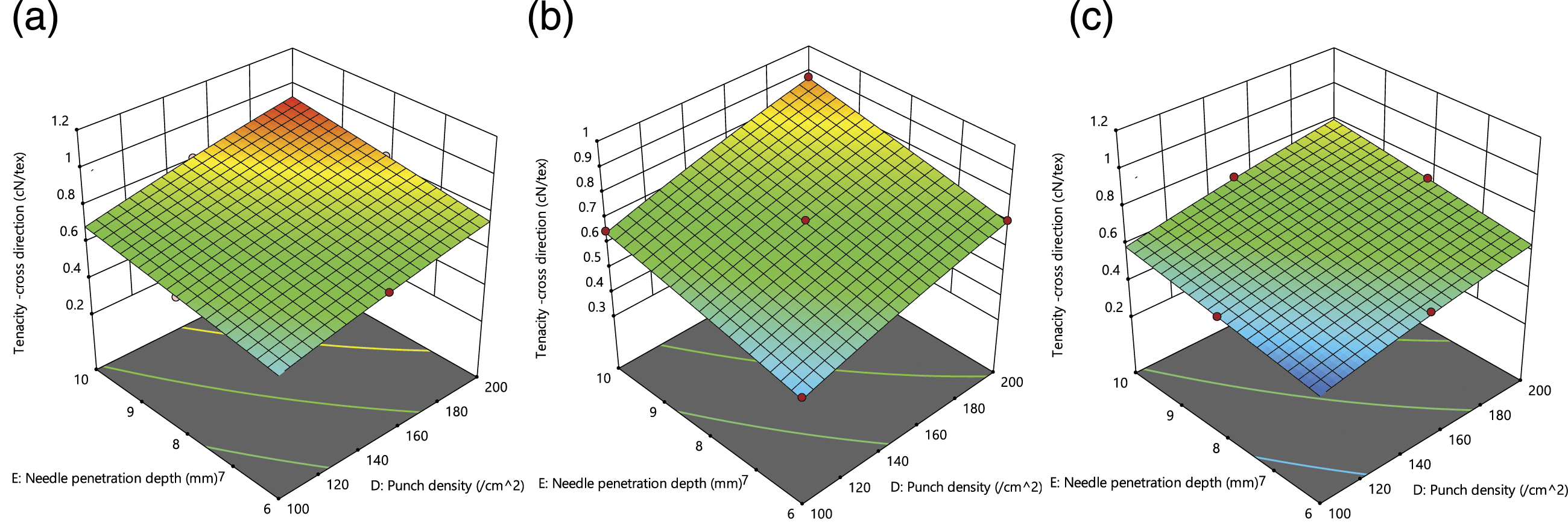
Figure 18 shows the 3D surface plots of needle penetration depth versus punch density, at three different feeder, cylinder, and doffer speeds. The increase of both punching parameters, at a respective feeder, cylinder and doffer speeds noticed an increase in fabric tenacity, but a reduction with the increase in all three carding parameters. The fabric tenacity observed an initial increase and, then, decrease with the increase in carding and punching parameters. Needle Punched Non-woven Fabric tenacity in cross direction – needle penetration depth versus punch density, at different feeder, cylinder and doffer speeds.
Increasing feeder speed resulted in more isotropic fabric, as discussed above in anisotropy, therefore, more fibres were found in the cross direction and, as a result, cross-directional tenacity increased. Higher cylinder speeds offered better fibre opening, fibres got straighter and parallelized and, as a result, more fibres were found to be oriented in the machine direction. Therefore, machine directional tenacity increased and cross-directional tenacity decreased. The increased doffer speed played a role similar to cylinder speed, which influenced the fibres to be oriented in the machine direction and, as a result, the cross-directional strength decreased but machine directional strength increased. From the above discussion, it can be noticed that higher feeder speed increased fibre coverage area, whereas, both cylinder and doffer depicted an opposite effect. The resultant effect of the increase of all three carding parameters decreased the cross-directional tenacity and confirmed the domination of cylinder and doffer over the feeder speed. The fabric tenacity in cross direction continuously increased, with the increase of both punch density and needle penetration depth. The obtained above trends are supported by the work of Roy and Ishtiaque.23,31
The maximum 0.951 cN/tex fabric tenacity in cross direction was achieved at a combination of 0.197 m/min feeder speed, 100.478 m/min cylinder speed, 4.848 m/min doffer speed, 150.779 punch/cm2 and 8.685 mm needle penetration depth, using equation (5).
Air permeability
Variance analysis of air permeability.

The response surface equation for air permeability, in terms of coded factors and significant model terms, is represented in equation (6). Strong correlation was observed between air permeability and carding and punching parameters, with a R2 value of 0.764.
The 3D surface plots of needle penetration depth versus punch density, at three different feeder speeds, but at constant cylinder and doffer speeds are given in Figure 19. At the respective feeder speed, the air permeability visualized a decrease and, then, increased with the increase in both needle penetration depth and punch density. But a continuous increase was also observed with the increase in feeder speed. The increase of feeder speed, needle penetration depth and punched density, at constant cylinder and doffer speeds observed the decreasing trend of air permeability. Air permeability – needle penetration depth versus punch density, at different feeder speeds but constant cylinder and doffer speeds.
Figure 20 presents the 3D surface plots of needle penetration depth versus punch density, at three different cylinder speeds, but at constant feeder and doffer speeds. The increase in both needle penetration depth and punch density, at the respective cylinder speed noticed an initial decrease and, then, drastic increase in the value of air permeability. Also, almost a continuous decrease was observed with the increase in cylinder speed. The air permeability decreased with the increase in cylinder speed, needle penetration depth and punched density, while feeder and doffer speeds were kept constant. Air permeability – needle penetration depth versus punch density, at different cylinder speeds but constant feeder and doffer speeds.
Figure 21 presents the 3D surface plots of needle penetration depth versus punch density, at three different doffer speeds, but at constant feeder and cylinder speeds. A continuous decrease in air permeability was found with the increase in both needle penetration depth and punch density, at a lowered level of doffer speeds, but at a higher level, the air permeability increased. But the increase in doffer speed depicted an initial increase and, then, decreases in air permeability. A decrease in air permeability was observed with the increase in doffer speed, needle penetration depth and punched density, keeping feeder and cylinder speeds constant. Air permeability – needle penetration depth versus punch density, at different doffer speeds but constant feeder and cylinder speeds.
Figure 22 illustrates the 3D surface plots of needle penetration depth versus punch density, at three different feeder, cylinder, and doffer speeds in the machine direction. A decrease and, then, increase of air permeability was noticed with the increase in both needle penetration depth and punch density, at the respective feeder cylinder and doffer speeds. A decrease and, then, increase in air permeability was found with the increased feeder, cylinder and doffer speeds, keeping punch density and needle penetration depth constant. Air permeability – needle penetration depth versus punch density, at different feeder, cylinder and doffer speeds.
In previous discussion, it was mentioned that the mean flow pore size increased with the increase in feeder speed. It is a known fact that air permeability is proportional to the mean flow pore size, therefore, the increased feeder speed increases the air permeability. Because of better fibre opening, fibres got straighter and parallelized, as a result of mean flow pore size as well as the air permeability. Higher doffer speeds provided better fibre opening of fibre, therefore, less fibre curling was found in fibres and, as a result, mean flow pore size decreased, and, therefore the value of air permeability decreased. Higher feeder speeds provided less fibre opening, as well as larger pore size, but the cylinder and doffer showed completely opposite trend and the resultant effects of all three carding parameters ensured a decrease and, then, increase in air permeability. Here, the cylinder and doffer speeds dominated over the feeder speeds. The air permeability depicted an initial decrease and, then, increased with the increase of punch density and needle penetration depth. The above trends are supported by the work of Roy and Ishtiaque.31,39
Further, the process parameters of the carding and punching were optimised for the maximum value of air permeability, by using the equation (6). The combination of 0.154 m/min feeder speed, 182.716 m/min cylinder speed, 5.028 m/min doffer speed, 199.36 punch/cm2 and a needle penetration depth of 9.96 mm provided 95.962 cm3/cm2/m value of the air permeability.
Filtration efficiency of 5 μm particle
Variance analysis of filtration efficiency of 5 μm particle.

The response surface equation for filtration efficiency of 5 μm particles, in terms of coded factors and significant model terms is represented in equation (7). Very strong correlation was observed between filtration efficiency of 5 μm particles and carding and punching parameters, with a R2 value of 0.974.
The 3D surface plots of needle penetration depth versus punch density, at three different feeder speeds, but at constant cylinder and doffer speeds are shown Figure 23. The filtration efficiency for 5 μm particles initially increased with the increase in both punching parameters, but, at higher punching parameters, the efficiency decreased yet a reduction was noticed with the increase in feeder speed. The increase in feeder speed and both punching parameters, at constant cylinder and doffer speeds, depicted the increasing and then, decreasing trend of filtration efficiency. Filtration efficiency of 5 μm – needle penetration depth versus punch density, at different feeder speeds but constant cylinder and doffer speeds.
Figure 24 provides the 3D surface plots of needle penetration depth versus punch density, at three different cylinder speeds, but at constant feeder and doffer speeds. The increase in both punching parameters, at the respective cylinder speed, observed an initial increase and, thereafter, decrease in the value of filtration efficiency. But a continuous increase was visualized with the increase in cylinder speed. The filtration efficiency of 5 μm particles inferred a decrease with the increase in cylinder speed and punching parameters, keeping feeder and doffer speeds constant, but towards higher level of machine parameters, it depicted a reduction. Filtration efficiency of 5 μm – needle penetration depth versus punch density, at different cylinder speeds but constant feeder and doffer speeds.
Figure 25 provides the 3D surface plots of needle penetration depth versus punch density, at three different doffer speeds, but at constant feeder and cylinder speeds. An initial increase of filtration efficiency for 5 μm particles was found with the increase in both punching parameters, at the respective doffer speed, but towards higher punching parameters a reduction was noticed. But the increase of doffer speed showed primarily an increase, then, reduction of filtration efficiency. The filtration efficiency noticed an increase and, later, decrease with the increase in doffer speed and punching parameters, keeping feeder and cylinder speeds constant. Filtration efficiency of 5 μm – needle penetration depth versus punch density, at different doffer speeds but constant feeder and cylinder speeds.
Figure 26 shows the 3D surface plots of needle penetration depth versus punch density, at three different feeder, cylinder, and doffer speeds. The filtration efficiency of 5 μm particles observed an increasing and, then, decreasing trend, with the increase in punching parameters, at the three respective carding parameters. The filtration efficiency depicted an increase with the increase in all three carding parameters. The increase of punching and carding parameters noticed an increasing trend of filtration efficiency, but towards higher values of parameters, a decline was noticed. Filtration efficiency of 5μm– needle penetration depth versus punch density, at different feeder, cylinder and doffer speeds.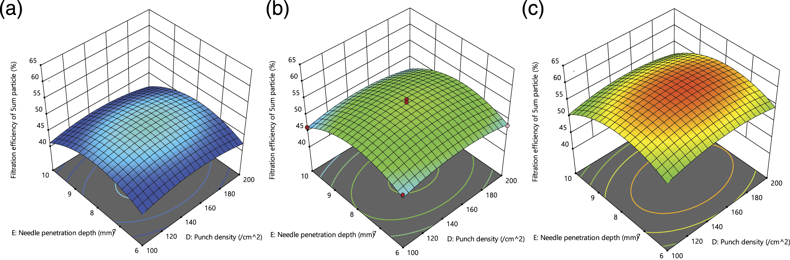
Higher feeder speed resulted in less opening of fibre, therefore, adding more bulk in the structure, which enhanced the value of mean flow pore size and, as a result, filtration efficiency of 3 μm particles decreased. The fibres got more oriented with higher cylinder and doffer speeds, therefore found more opportunities to get closer to each other, to enhance the packing fraction. It is well established that more packed fabric can restrict larger number of particles during filtration. Higher feeder speeds provided larger pore size, but the cylinder and doffer showed completely opposite trend and the resultant effect of all three carding parameters ensured an increase in filtration efficiency of 3 μm particles. Here the cylinder and doffer speeds dominated over the feeder speeds. The increase of punch density and needle penetration depth showed an increasing and decreasing trend of the filtration efficiency. The obtained above trends are supported by the work of Roy and Ishtiaque.22,23
The carding and punching were optimised for the maximum value of filtration efficiency for 5 μm particles, by using the equation (7). The combination of 0.167 m/min feeder speed, 249.22 m/min cylinder speed, 6.699 m/min doffer speed, 143.022 punch/cm2 and 7.85 mm needle penetration depth provided 60.696% value of the filtration efficiency.
Overall optimization
Required goals set for optimization process.

Optimized machine parameters and properties.
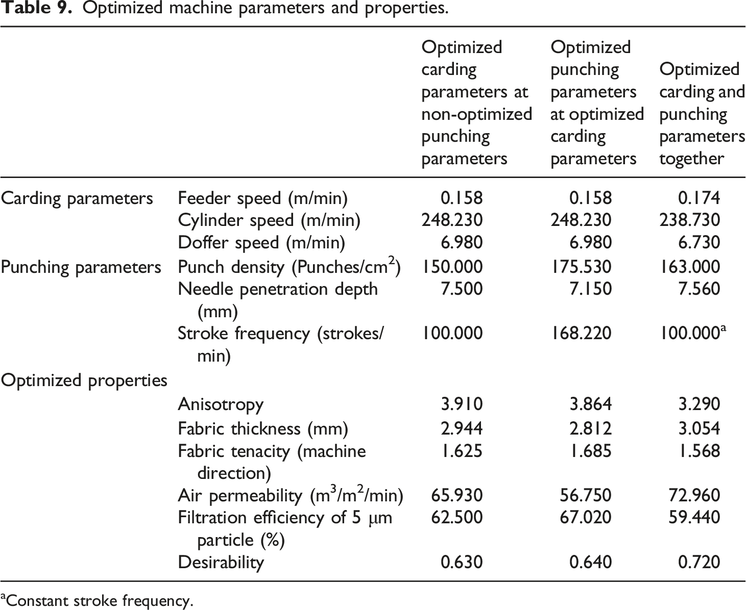
aConstant stroke frequency.
Conclusions
It is observed that anisotropy increases with the increase of cylinder and doffer speed but decreases with the increase of feeder speed, punch density, and needle penetration depth. The fabric thickness reduces with the increase of cylinder speed, doffer speed, punch density and needle penetration depth, but increases with the increase of feeder speed, whereas the fabric tenacity (in the machine direction) follows an opposite trend of fabric thickness. It is also noticed that the fabric tenacity in the cross direction decreases with the increase of cylinder and doffer speed but increases with the increase of feeder speed, punch density and needle penetration depth. The air permeability initially decreases and, then, slightly increases with the increase of cylinder and doffer speed, but continuously increases with the increase of feeder speed. The air permeability initially decreases and then, increases with the increase of punch density and needle penetration depth. Interestingly, the filtration efficiency confirms an initial increase and then, a slight decrease with the increase of cylinder speed, doffer speed but an increase in feeder speed has shown a decreasing trend. Whereas, the filtration efficiency followed an initial increase and, then, a drop in value with the increase of punch density and needle penetration depth.
Footnotes
Declaration of conflicting interests
The author(s) declared no potential conflicts of interest with respect to the research, authorship, and/or publication of this article.
Funding
The author(s) received no financial support for the research, authorship, and/or publication of this article.