
Abstract
Poly(p-phenylenetere phthamide) fiber is a high-performance synthetic fiber whose reinforced composites are widely used for their advantages of high strength and lightweight. However, the further potential usage of poly(p-phenylenetere phthamide) and its reinforced composites is limited in areas such as antistatic materials, conducting materials, and electromagnetic shielding materials due to their high electrical insulation. To improve the electrical conductivity, an online polymerization coating technology was used to manufacture conductive poly(p-phenylenetere phthamide)/polyaniline composite yarns continuously. The conductive poly(p-phenylenetere phthamide)/polyaniline composite yarns’ structure and properties such as surface morphology, electrical conductivity, Fourier-transform infrared spectroscopy spectra, thermogravimetric performance, and mechanical properties were studied in details. Then, three kinds of multiaxial composites were prepared by using the conductive poly(p-phenylenetere phthamide)/polyaniline composite yarn as the reinforcement and unsaturated polyester resin as a matrix, and the electromagnetic shielding performance of the composites was measured. The results indicated that the conductivity of conductive poly(p-phenylenetere phthamide)/polyaniline composite yarn can reach to ∼160 S/m. The thermogravimetric performance of poly(p-phenylenetere phthamide) was reduced after conductive treatment. The mechanical properties of the composite yarns, such as the breaking strength and elongation, remained unchanged when the oxidant concentration was lower than 0.6 mol/L and decreased with the increase in the oxidant concentration. The electromagnetic shielding composites show a certain anti-electromagnetic radiation capability, and the shielding effectiveness value increased with the axial number and density of the conductive poly(p-phenylenetere phthamide)/polyaniline composite yarns. For the tetra-axial composite with a conductive yarn density of 37 yarns per inch, the average shielding effectiveness value in the frequency range of 100 MHz to 1500 MHz can exceed 22 dB.
Keywords
Introduction
The human living environment is inundated with various electromagnetic waves. While offering convenience to our lives, electromagnetic waves also cause many problems. For instance, they interfere with electronic instruments and affect data communication; even the security of national information and military secrets can be compromised via electromagnetic leakage. Moreover, human health can be affected by electromagnetic waves through the thermal effect, nonthermal effect, and cumulative effect. According to the World Health Organization (WHO), electromagnetic radiation is the fourth largest source of environmental pollution, after water, air, and noise. Therefore, electromagnetic radiation has become a serious problem for public safety and health, which should be given more attention.
Shielding the radiation source is the most direct and effective way to reduce the harm caused by electromagnetic radiation. Metals such as stainless steel, nickel, copper, silver, and gold have excellent electromagnetic shielding performance due to their high electrical conductivity, but their disadvantages of high density, high cost, and difficulty in processing restrict their applications in numerous fields. Conductive fiber—a new type of soft, lightweight material—has played an increasingly important role in the field of electromagnetic shielding materials. Fabrics and composites made of conductive fiber have replaced metals to become a new generation of electromagnetic shielding materials in increasing areas [1].
With its excellent properties of high strength, high modulus, chemical resistance, and fatigue resistance, poly(p-phenylenetere phthamide) (PPTA) fiber is regarded as a high-tech synthetic fiber. PPTA fiber-reinforced composites show the characteristics of high strength and light weight. With the rapid development of science and technology, the usage of PPTA fiber-reinforced composites has been extended from the frontier to the general industry, including aerospace, transportation, construction, sports equipment, biology, medicine, energy, and environmental protection.
Excellent electrical insulation is also an important characteristic of the PPTA fiber. On one hand, the characteristic promote the application of PPTA fiber in high-strength insulation materials such as radar covers; on the other hand, it limits its usage in antistatic materials, conductive materials, and electromagnetic shielding materials. Obtaining great electrical property of PPTA fiber will develop a broader market in electronics, military industry, protection, and other fields. Obviously, a high-strength and lightweight electromagnetic shielding composite material is crucial for such applications.
Metallization is an efficient method for endowing PPTA fiber with excellent electrical conductivity by functionalizing the fiber surface with one or more layers of metal, such as gold, silver, copper, or nickel. For instance, Schwarz et al. [2] deposited a thin layer of soft gold onto PPTA yarns in an electroless way, and the gold-coated yarns showed excellent electrical conductivity combined with good mechanical properties. Little et al. [3] metallized PPTA fibers via electroless nickel deposition and then prepared PPTA–nickel–gold fibers via an electrochemical gold plating process; the conductivity of the resulting fibers reached 600 S/m. Zhang et al. [4] coated the surface of PPTA fibers with a layer of silver via the electroless plating method, yielding the conductivity as high as 400 S/m. Yu et al. [5] prepared silver-plated PPTA fiber after the fiber surface was covered by a catalytical film, and good conductivity (260 S/m) as well as outstanding durability was obtained. Wang et al. [6] immobilized silver nanoparticles on the surface of PPTA fibers via the functionalization of the fibers with poly (dopamine), followed by electroless silver plating, and the conductivity of the silver-plated PPTA fiber reached 105 S/m. Martinez et al. [7] and Zhao et al. [8] demonstrated a method for producing conductive PPTA fiber with nickel and copper coating using supercritical fluid carbon dioxide. Liang et al. [9] prepared conductive aramid fiber with nickel–copper composite coating using the metalation swelling method. Fatema and Gotoh [10] presented a new electroless nickel plating procedure for aramid fiber.
In addition to metals, intrinsic conductive polymers (ICPs) can be used for the conductive treatment of fibers. Among the ICPs, polyaniline (PANI) is regarded as the most promising due to its advantages of low cost, easy synthesis, high conductivity, and good stability [11]. Using PANI as a conductive component, conductive PANI fibers can be prepared via conventional methods, such as solution spinning [12,13] melt spinning [14,15], and electrostatic spinning [16,17]. However, it is difficult for PANI to dissolve or melt; thus, the distribution of large PANI particles in the fiber matrix is harmful for the mechanical and electrical properties of these fibers because of the poor compatibility of PANI with the fiber matrix. Hence, the aforementioned conventional methods are not suitable for the preparation of conductive PANI fibers, especially high-strength PPTA fiber. Surface modification, such as in situ polymerization of the aniline monomer, is effective for preparing conductive PANI fiber with a high-purity PANI conductive layer on the fiber surface.
The preparation of conductive PANI fibers via in situ polymerization began approximately three decades ago [18]. It is regarded as the most commercially promising method for its advantages of simple preparation, small influence on the mechanical properties of the matrix fiber, and high conductivity of the conductive fiber. Various studies have been performed on the preparation of conductive fibers via in situ polymerization from natural fibers [19–22] and chemical fibers [23,24]. It has been reported that PPTA fiber is used as the base material for conducting treatment via in situ polymerization. Shao et al. [25] prepared conductive PPTA/PANI composite fibers via the encapsulation of PPTA fiber with PANI after the modification of the surface of the PPTA fiber with epichlorohydrin, and the lowest room temperature resistivity of the composite fiber was approximately 3 × 10⁻⁶ S/m. Li et al. [26] optimized the preparation process of in situ polymerization from aspects such as the kind and concentration of oxidant and doping acid, concentration of aniline monomer, reaction time, and temperature, and the highest conductivity of the resulting conductive PPTA/PANI composite fiber was 47 S/m.
However, due to the step-by-step process in solutions of in situ polymerization, the efficiency of conventional in situ polymerization for the preparation of conductive PANI fiber is very low. The studies are confined to the laboratory, and it is difficult to realize large-scale commercial production at present. In our previous work, we presented a novel method for preparing conductive PANI yarn continuously via in situ polymerization and prepared conductive ultrahigh molecular polyethylene yarn [27,28], conductive polytrimethylene terephthalate yarn [29], and conductive polyester yarn [30]. In the latest study, the consumption of materials such as aniline, doped acid, and oxidant was significantly reduced, which is conducive to the industrialization of conductive PANI fibers [31].
Therefore, an efficient and low-cost method for preparing conductive PANI-coated PPTA yarn was used in this study. An online polymerization coating technology based on in-situ polymerization was used to prepare conductive PPTA/PANI composite yarns continuously, and the structure and property of the conductive yarns were studied. Subsequently, multiaxial composites for electromagnetic shielding were prepared via hand molding, which using the conductive PPTA/PANI composite yarn as the reinforcement and unsaturated polyester resin (UPR) as matrix. Then, the electromagnetic shielding performance of the composites was studied.
Experimental
Materials
PPTA filament yarn of 1036.5 dtex/395f (Yantai Tayho Advanced Materials Co., Ltd., China) was used as a substrate. Aniline (An) (Lingfeng Chem Co., Ltd., China), ammonium persulfate (APS) (LingfengChem Co., Ltd., China), and hydrochloric acid (Zhongxing Chem Reagent co., LTD., China) were used as the monomer, oxidant, and dopant, respectively. UPR (Baiqian Chemical co., LTD., China) was used as the matrix of the composites. The accelerator and curing agent used in the preparation of the composites were purchased on the market.
Preparation of conductive PPTA/PANI composite yarns
The conductive treatment of the PPTA filament yarn was applied using a home-made yarn conductive treatment device, as shown in Figure 1. PPTA filament yarn was drawn from a bobbin and passed through two dip tanks successively. The first tank was filled with an HCl/An mixture, and the second one was filled with an APS solution. After adsorbing HCl and An in the first tank, the yarn was pulled through the APS solution and adsorbed the APS solution immediately. Then, the yarn was drawn away and put in a container, so that the attached An, HCl, and APS could be oxidized and polymerized in a nonliquid phase environment to form a PANI conductive layer on the yarn surface. The specific process was presented in our previous work [31] and will not be repeated here. The concentration of the HCl/An mixture was 3 mol/L, the speed of the conductive treatment of the yarn was 20 m/min, and the concentrations of APS were 0.2, 0.4, 0.6, 0.8, 1.0, 1.2, and 1.4 mol/L. The resulting conductive PPTA/PANI composite yarns were called PPTA/PANI-0.2, PPTA/PANI-0.4, PPTA/PANI-0.6, PPTA/PANI-0.8, PPTA/PANI-1.0, PPTA/PANI-1.2, and PPTA/PANI-1.4, respectively.

Homemade device for the conductive treatment of the PPTA/PANI yarn. 1: robbin, 2: tensioner, 3: HCL/An mixture tank, 4: immersing roller, 5: press roller, 6: APS tank, 7: overflow pipe, 8: APS container, 9: flow control switch, 10: press roller, 11: friction traction wheel, 12: waste liquor dish, and 13: yarn storage container.
Preparation of conductive yarn-reinforced multiaxial composites
Two circular hollow stainless-steel molds were previously fabricated with a thickness of 1 mm and an inner diameter of 11.5 cm. The conductive PPTA/PANI composite yarn with the highest conductivity was pasted on one side of one mold with double-sided adhesive tape via three methods, as shown in Figure 2. In Figure 2(a), the yarn was pasted biaxially, and the angle of the two groups of yarn was 90°. In Figure 2(b), the yarn was pasted tri-axially, and the angle of the three groups of yarn was 60°. In Figure 2(c), the yarn was pasted tetra-axially, and the angle of the four groups of yarn was 45°. Four yarn densities (13 yarns per inch, 21 yarns per inch, 29 yarns per inch, and 37 yarns per inch) were applied.

Arrangements of the conductive PANI-coated PPTA yarns: (a) biaxial, (b) triaxial, and (c) tetra-axial.
UPR was used as the matrix of the composites. The accelerator (mainly composed of iso-octanoic acid and styrene) was added to the UPR, and after stirring for 0.5 h, the curing agent (methyl ethyl ketone peroxide) was added, followed by mixing for uniformity (the mass ratio of the accelerator, curing agent, and UPR was 1:2:100). The mold with yarn was placed on a polytetrafluoroethylene plate (the side with the yarn facing up), and the other mold was pressed on it. The prepared resin was slowly poured into the stainless-steel mold and spread evenly using a glass rod to ensure that the yarns were soaked with UPR. Then, a polytetrafluoroethylene plate was placed on top of the mold, and a weight of 5 kg was put on the plate to make the UPR fully permeate the space between the yarns and cause the excess UPR to be squeezed out. Then, the mold was inserted into a constant-temperature oven of 80°C for 2 h to cure the UPR. After cooling and cutting off the excess yarn, the cured composite material was removed from the mold, as shown in Figure 3.

Appearance and inner structure of conductive PANI-coated PPTA yarn-reinforced composites.
Characterization
Surface morphology
The surface morphology of the PPTA yarns before and after the conductive treatment and the cutting surface morphology of composite material were examined using an SNE-300M scanning electron microscope (SEC Co., Ltd, South Korea).
Electrical conductivity
The electrical resistance of the conductive PPTA/PANI composite yarns was measured using a TH2516 DC resistance meter (Tonghui Electronic Co. Ltd, China). The test length of the composite yarns was 2.5 cm. Each yarn was tested 20 times, and the electrical conductivity was calculated as follows

Fourier transform infrared (FT-IR) spectra
The FT-IR spectra of the PPTA and PPTA/PANI were tested using an IR Prestigae-21 infrared spectrometer (Shimadzu Corporation, Japan) in the range of wave numbers from 4000 to 500 cm−1 via the potassium bromide disk method.
Thermogravimetric analysis (TGA)
The TGA of PPTA and PPTA/PANI was performed using a TG/DTA 6300 simultaneous thermal analyzer (NSK Ltd., Japan) in the range of temperature from 50°C to 600°C at a heating rate of 10°C/min under an air flow of 20 cm3/min.
Mechanical properties
The mechanical properties of the PPTA yarns before and after conductive treatment were measured using an Instron 3365 universal material testing machine (Instron Co., USA). The gauge length was 250 mm, and the crosshead speed was 250 mm/min. Each sample was tested 10 times, and the main mechanical performance indices, including the tensile strength, elongation at break, and initial modulus, were recorded and calculated.
Electromagnetic shielding effectiveness of composites
The electromagnetic shielding effectiveness of the conductive PANI-coated PPTA yarn-reinforced composites was measured using the coaxial method according to the ASTM D4935-99 Standard Test Method for Measuring the Electromagnetic Shielding Effectiveness of Planar Materials. The testing device contained a DN 1015 A Flange Coaxial Clamp (Electromagnetic Compatibility Lab of Southeast University, China) and an E5061A Vector Network Analyzer (Agilent Technologies Co., Ltd, USA), along with an attenuator (10 dB). The frequency of the plane wave tested was in the range of 100 MHz to 1500 MHz.
The shielding rate of the composites for the electromagnetic waves was calculated as follows
Results and discussion
Structure and properties of conductive PPTA/PANI composite yarns
Surface morphology
Figure 4 shows the surface morphology of the PPTA yarn before and after the conductive treatment: (a) shows the untreated PPTA yarn, and (b)–(h) show PPTA/PANI-0.2, PPTA/PANI-0.4, PPTA/PANI-0.6, PPTA/PANI-0.8, PPTA/PANI-1.0, PPTA/PANI-1.2, and PPTA/PANI-1.4, respectively. The SEM images indicate that the surface of the untreated PPTA fiber was smooth and uniform and that the conducting treatment caused significant changes. When the APS concentration was low, there was a small amount of granular PANI on the fiber surface. With the increase in the APS concentration, the density and size of granular PANI were increased, and PANI with discontinuous film structure was formed on the fiber surface, as shown in (b)–(d). With the further increase in the APS concentration, a relatively continuous PANI conductive layer was gradually formed on the fiber surface, as shown in (e). When the APS concentration was increased to 1.0 mol/L, the PANI basically covered the fiber surface and had a certain thickness, as shown in (f). When the APS concentration increased to 1.2 and 1.4 mol/L, the fiber surface was completely coated by PANI, and moreover, the gap between the fiber and fiber was filled with PANI with large-scale size agglomeration, as shown in (g) and (h). Clearly, the PANI content on the yarn surface increased with the APS concentration in the experimental range of this study.
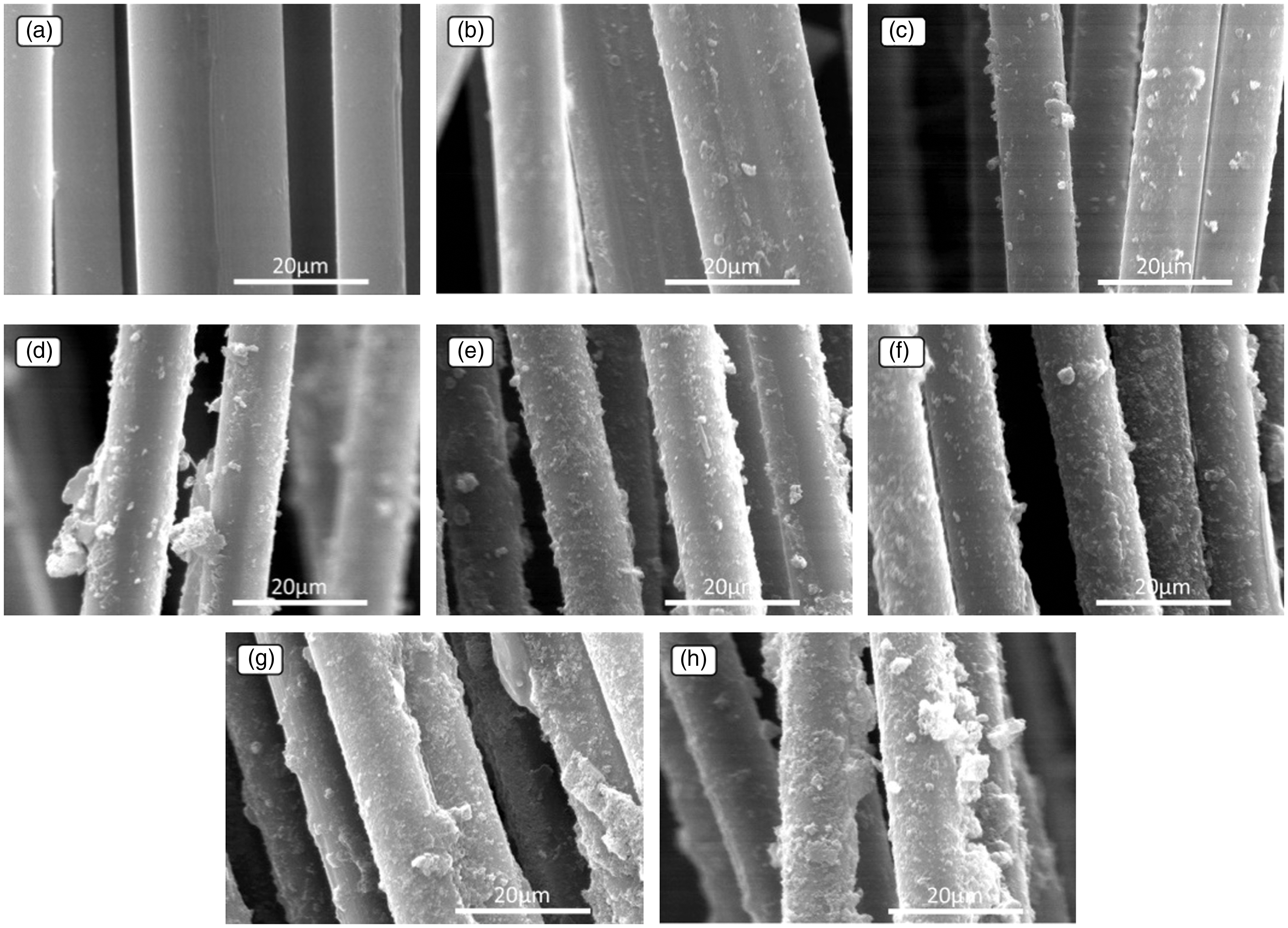
SEM micrographs of (a) PPTA, (b) PPTA/PANI-0.2, (c) PPTA/PANI-0.4, (d) PPTA/PANI-0.6, (e) PPTA/PANI-0.8, (f) PPTA/PANI-1.0, (g) PPTA/PANI-1.2, and (h) PPTA/PANI-1.4.
The PANI content on the yarn surface was analyzed quantitatively in terms of the weight gain rate (ratio of PANI to the quality of the original yarn), and the effect of the APS concentration on the weight gain rate of the PPTA yarn is shown in Figure 5. Here, we observe that the weight gain rate increased from <2% when the APS concentration was 0.2 mol/L to approximately 40% when the APS concentration was 1.4 mol/L, which is consistent with the change shown in Figure 4.

Effect of the APS concentration on the weight gain rate of PPTA/PANI.
Electrical conductivity
Figure 6 shows the effect of the APS concentration on the electrical conductivity of the conductive PPTA/PANI composite yarns. When the concentration of APS was 0.2 mol/L, the conductivity of the resulting composite yarn was only ∼4 S/m. With the increase in the APS concentration, the conductivity of the composite yarns improved gradually, and when the APS concentration was 1.0 mol/L, the conductivity of resulting composite yarn peaked at ∼160 S/m, which is approximately two to three times higher than that of the conductive fiber prepared via the traditional in situ polymerization [21]. However, with the further increase in the APS concentration, the conductivity of the composite yarn declined sharply; when the APS concentration increased to 1.4 mol/L, the conductivity decreased to ∼40 S/m, which is approximately 1/4 of the highest value.

Effect of the APS concentration on the electrical conductivity of PPTA/PANI.
The influence of the PANI conductive layer on the conductivity of the PPTA/PANI composite yarn is manifold. From the aspect of the macroscopic structure, the morphological structure of the PANI conductive layer on the fiber surface, i.e., the thickness and continuity, affects the efficiency of the charge carriers. From the above analyses of the surface morphology and weight gain rate of the conductive yarn, it can be seen that as the APS concentration increases, the thickness and continuity of the PANI conductive layer on the fiber surface gradually increase, forming a good electric channel; thus, the conductivity gradually increases. However, when the APS concentration increased to >1.0 mol/L, although the thickness and continuity of the PANI on the fiber surface continued to increase, the conductive capacity of APS decreased significantly. This is mainly because PANI is different from metals, and its conductivity varies greatly under different microstructures.
The microstructure of PANI is composed of reduction units and oxidation units, which can be expressed as follows
The macromolecular chain of PANI contains not only oxidation units with benzene rings arranged alternatively with quinone rings but also reduction units with benzene rings arranged continuously. The y value (which can be changed in the range of 0–1) in the chemical structure formula represents the degree of oxidation of PANI. If the y value is different, the degree of oxidation of PANI is different, and the corresponding PANI exhibits significant differences in the structure, components, color, and conductivity. The typical PANI structure can be divided into three types: y = 1, y = 0, and y = 0.5, which are the stable oxidation states of PANI. Values of 1 and 0 for y correspond to the complete return state (leucoemeraldine, LEB) of the all-benzene structure and the complete oxidation state (pernigraniline, PB) of the “benzene-quinone” alternating structure, respectively. A y value of 0.5 corresponds to the intermediate oxidation states (emeraldine, EB) of semi-oxidation and semi-reduction, and the ratio of benzene to quinone in the molecular chain is 3:1. Of the three structures, only the intermediate oxidation state can change from the insulating state to the conductive state through doping [32], while the transition degree of conductivity in other oxidation states is relatively poor. That is, in the same doping state, with the increase of APS concentration, the oxidation degree or the y value of PANI increase from 0 to 1, thus the conductivity of PANI first increases and then decreases.
In addition to the molecular structure, the uniformity of PANI’s macroscopic structure also has a significant effect on its electrical conductivity. With the increase of APS concentration, the agglomeration phenomenon of PANI on the fiber surface becomes more and more obvious. The particle size of the agglomeration gradually increases, and the uniformity of the structure decreases, which will lead to obstructed passage of carriers, and thus reduced conductivity. Therefore, under the joint influence of the PANI macrostructure and microstructure, with the increase in the APS concentration, the conductivity of conductive PPTA/PANI composite yarns first increases and then decreases.
FT-IR
The FT-IR spectra of PPTA and PPTA/PANI-1.0 (with the highest conductivity) are shown in Figure 7. In curve (a) (corresponding to PPTA), the characteristic peak at 1645.23 cm−1 is corresponding to the stretching vibration of amide bond C=O (belong to amide Iband), the characteristic peak at 1 541.12 cm−1 is corresponding to coupled vibration of C–N stretching vibration and N–H bending vibration (belong to amide II band), the characteristic peak at 1396.42 cm−1 is corresponding to the asymmetric stretching vibrations of N–C=O, the peak at 1 305.81 cm−1 is corresponding to the C–N stretching vibration in benzene ring, the peak at 1 222 cm−1 is corresponding to the C–N stretching vibration and N–H bending coupling vibration (belong to amide III band), the three peaks at 1 111.00, 1 014.56 and 977.91 cm−1 are all corresponding to the in-plane bending vibration of C-H in benzene ring, and the peak at 725.23 cm−1 is corresponding to the out-of-plane bending vibration of N–H.

FTIR curves of PPTA and PPTA/PANI-1.0.
Compared with PPTA, it can be found that many new characteristic peaks formed in the infrared curve of PPTA/PANI-1.0. Including the in-plane bending vibration of the benzene ring in 905.02 cm−1, the benzene structure (N–B–N) stretching vibration in 1506.58 cm−1, and the stretching vibration of the quinone structure (N=Q=N) in 1608.15 cm−1. The presence of these characteristic peaks indicates that the yarn is coated with PANI containing both oxidation and reduction units, which proves that the conductive PANI is formed on the surface of the yarn.
TGA
The TGA curves of PPTA and PPTA/PANI-1.0 are shown in Figure 8. It can be seen from Figure 8, PPTA and PPTA/PANI-1.0 showed similar thermal degradation behaviors at temperature below 100°C, a weight loss about 4% occurred in both of them may corresponding to the evaporation of the absorbed water in the fibers. While at higher temperature, the thermal stability of PPTA was obviously higher than that of PPTA/PANI. For example, from 100°C to 480°C, before the main decomposition, the weight loss of PPTA is only ∼6% while PPTA/PANI is ∼21%. An obvious weight loss about 5% in PPTA/PANI from 272°C to 306°C may corresponding to the decomposition of residual doping acid, oxidant, and PANI oligomers, and the weight loss occurred below 480°C may corresponding to the degradation of PANI macromolecular chain [33].

TG curves of PPTA and PPTA/PANI.
Some thermal characteristics such as the temperature at 10% (T10%), 50% (T50%), and 90% (T90%) weight loss, the maximum weight loss rate (Tp) and the final temperature (Tf), mass retention at 400°C (Wt400) and at 600°C (Wt600) of PPTA and PPTA/PANI-1.0 are presented in Table 1. The results show that the thermal stability of PPTA/PANI is lower than that of PPTA, i.e., the presence of PANI reduces the thermal stability of the PPTA.
Thermal characteristics of poly(p-phenylenetere phthamide) (PPTA) and PPTA/polyaniline (PANI).

Mechanical property
Figure 9 shows the stress–strain curves of PPTA and PPTA/PANI, and Figure 10 compares the breaking strength, breaking elongation, and initial modulus of conductive PPTA/PANI composite yarns prepared under different process conditions and PPTA filament yarn. There are two situations in which conductive treatment affects the mechanical properties of PPTA filament yarn. First, when the APS concentration was no more than 0.6 mol/L, compared to those of the untreated one, the breaking strength and breaking elongation of the treated yarns increased slightly when the breaking strength increased by 5%–6%, and the breaking elongation increased by 2.6%–5.6%, but the initial modulus was basically unchanged. Second, when the APS concentration was greater than 0.8 mol/L, the mechanical properties of the treated yarns were decreased compared to those of the original one, and with the increase in the APS concentration, the performance decreased more obviously. For example, the sample of PPTA/PANI-1.0, with the highest conductivity (APS concentration is 1.0 mol/L), exhibited reductions of 13%, 12%, and 7% in its breaking strength, breaking elongation, and initial modulus, respectively, compared to those of the untreated yarn. When the APS concentration increased to 1.4 mol/L, the breaking strength, breaking elongation, and initial modulus of the resulting conductive yarn decreased by approximately 28%, 23%, and 10%, respectively.
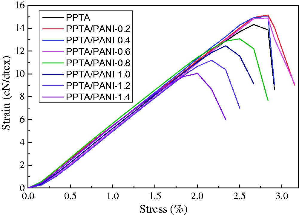
Stress–strain curves of PPTA and PPTA/PANI.
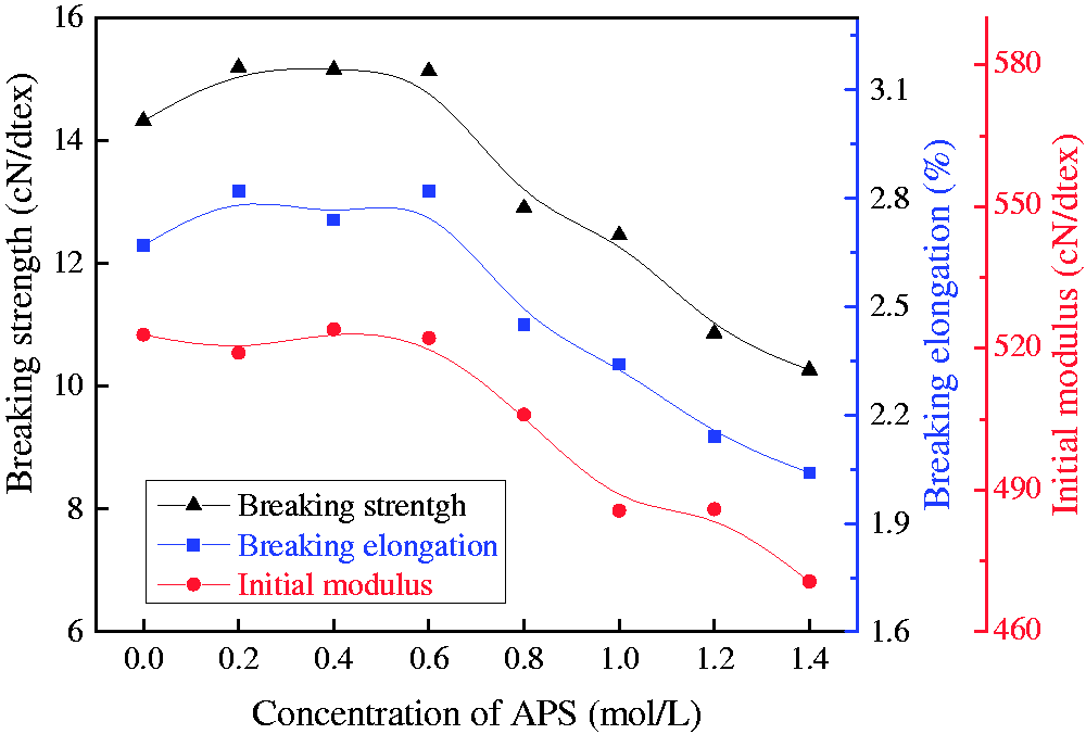
Mechanical properties of PPTA and PPTA/PANI.
When the APS concentration is low, the mechanical properties of yarn are enhanced, mainly because the PANI formed on the surface and in the gap between the fibers of the yarn are glued together. When the yarn was stretched, the asynchrony in the breaking of the fibers was reduced; thus, the mechanical properties were slightly improved. However, when the APS concentration exceeded 0.8 mol/L, the residual APS was attached to the surface of the PPTA fiber for a long time after the reaction, causing oxidative damage to the fiber and degrading the mechanical properties. Therefore, with the increase in the APS concentration, the mechanical properties of the conductive PPTA/PANI composite yarns remained unchanged or even improved slightly and then declined significantly. Thus, to ensure that the mechanical properties are not degraded, the content and proportion of the material adsorbed on the yarn surface should be strictly controlled.
Electromagnetic shielding performance of conductive PANI-coated PPTA yarn-reinforced composites
The PPTA/PANI-1.0, which had the highest conductivity (∼160 ± 10 S/m), was selected to be used as the reinforcement of composites. The electrical resistance of 2.5 cm yarn was tested every 1 m for 100 times, and the electrical conductivity was calculated, as shown in Figure 11. The maximum value of the conductivity in this part was 189 S/m, the minimum value was 140 S/m, the mean value was 166 S/m, and the coefficient of variation was only8.43%, showing good uniformity.

Electrical conductivity of PPTA/PANI-1.0 over 100 m.
The electromagnetic shielding effectiveness of conductive PANI-coated PPTA yarn-reinforced biaxial, triaxial, and tetra-axial composites is shown in Figure 12(b)–(d). For comparison, the electromagnetic shielding effectiveness of composites (tetra-axial, 37 yarns per inch) reinforced by common PPTA yarn is shown in Figure 12(a). The SE values for 187 points in the frequency range of 100 MHz to 1500 MHz were averaged, and the shielding rate of the composites for electromagnetic waves was calculated according to equation (2). The results are shown in Table 2.
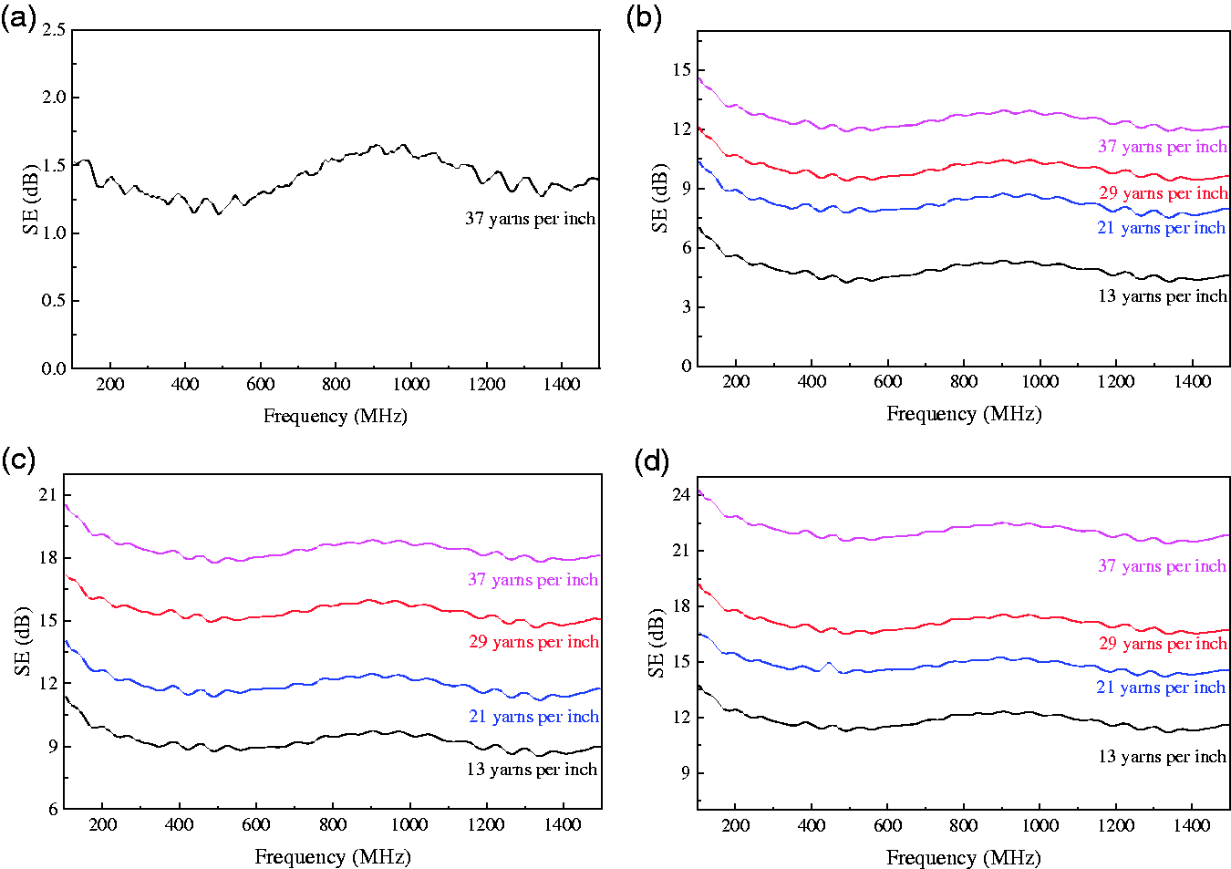
Electromagnetic SE for (a) PPTA yarn-reinforced, (b) biaxial, (c) triaxial, and (d) tetra-axial conductive PANI-coated PPTA yarn-reinforced composites.
Mean shielding effectiveness (SE) value and shielding rate of composites.

PPTA: poly(p-phenylenetere phthamide); PANI: polyaniline.
The common PPTA yarn reinforced composites have almost no electromagnetic shielding function, the mean SE value of it is only 1.4 dB, and the shielding rate is 27.56%. The application of conductive PANI-coated PPTA yarn in composites increases their ability to resist electromagnetic radiation. Under the same density of conductive yarn, the SE value of the composites increased with the increase in axial number. At the same time, the SE value of the composites increased with the increase in density of the conductive yarn. For the biaxial composite with a conductive-yarn density of 13 yarns per inch, the average SE value was only 4.89 dB; that is, the average shielding rate for electromagnetic waves within the range of 100 MHz to 1500 MHz was 67.56%. For the tetra-axial composite material with a conductive-yarn density of 37 yarns per inch, the average SE value increased to 22.09 dB, that is, the average shielding rate for electromagnetic waves within the range of 100 MHz to 1500 MHz was 99.38%.
The wavelength of the electromagnetic waves with frequency of 100 MHz to 1500 MHz ranged from 3 to 0.2 m. Theoretically, the direct transmission of electromagnetic waves does not change greatly as long as the interval of the conductive yarn is <0.2 m. In this study, the interval of the conductive yarn was far less than 0.2 m. Therefore, with the increase in the density and axial number of the conductive PPTA/PANI composite yarns, the improvement of the SE value is mainly attributed to the microwave absorption characteristics of PANI. PANI with high conductivity can effectively absorb electromagnetic waves in the microwave frequency band (30 MHz–30 GHz). At the same time, the conductive PPTA/PANI composite yarns produce inductive current under the action of electromagnetic waves, which weakens the penetration of electromagnetic waves according to Lenz’s law. Therefore, with the increase in the density and PANI content of the conductive PPTA/PANI composite yarns, the electromagnetic shielding performance of the composites is gradually improved.
Conclusions
To improve the electrical conductivity of PPTA fiber and expand its potential applications in antistatic materials, conducting materials, and electromagnetic shielding materials, a novel method based on in situ polymerization was used to prepare conductive PPTA/PANI composite yarns continuously. The effect of the preparation conditions such as the APS concentration on the conductivity of the PPTA/PANI composite yarns was analyzed, and the surface morphology and mechanical properties of the composite yarns were studied. Conductive PANI-coated PPTA yarn-reinforced biaxial, triaxial, and tetra-axial composites for electromagnetic shielding were prepared via hand molding by using the conductive PPTA/PANI composite yarn as the reinforcement and UPR as a matrix. The effects of the axial number and density of the conductive yarn on the electromagnetic shielding performances of the composites were studied. The following conclusions were drawn. The conductive PANI was formed on the surface of the PPTA fibers after the conductive treatment based on in situ polymerization. The PANI content on the yarn surface increased with the APS concentration. The uniform conductive layer endowed the PPTA yarn with good conductive performance. When the APS concentration was 1.0 mol/L, the highest conductivity of the PPTA/PANI composite yarn was 166 S/m. The thermogravimetric performance of PPTA was reduced after conductive treatment. PPTA and PPTA/PANI showed similar thermal degradation behaviors at temperature below 100°C, while at higher temperature, the thermal stability of PPTA was obviously higher than that of PPTA/PANI. The mechanical properties such as breaking strength, breaking elongation, and initial modular of the PPTA yarn changed with the conductive treatment. When the oxidant concentration was <0.6 mol/L, the mechanical properties were slightly improved. However, when the oxidant concentration was >0.8 mol/L, the mechanical properties were degraded. The composites strengthened by the conductive PPTA/PANI composite yarn exhibited a certain anti-electromagnetic radiation capability, and the SE value increased with the axial number and the density of the conductive PPTA/PANI composite yarns. For a tetra-axial composite material with a conductive-yarn density of 37 yarns per inch, the average SE value was 22.09 dB; that is, the average shielding rate for electromagnetic waves within the range of 100 MHz to 1500 MHz was >99%.
Footnotes
Declaration of conflicting interests
The author(s) declared no potential conflicts of interest with respect to the research, authorship, and/or publication of this article.
Funding
The author(s) disclosed receipt of the following financial support for the research, authorship, and/or publication of this article: This work is supported by the Public Welfare Technology Application Research Project of Shaoxing City (2018C10016), the China Postdoctoral Science Foundation (2017M621976), the Scientific Research Foundation of Shaoxing University (2017LG1006), and the international science and technology cooperation project of Shaoxing University (2019LGGH1003).