
Abstract
In this work, three types of multi-layered fibrous materials with different middle layer structures, including Struto nonwoven, Struto nonwoven with air pockets and Struto nonwoven with air pockets filled by aerogel particles, were prepared based on laser engraving technique and laminating method. A custom-built new device was fabricated to evaluate convective thermal behaviour of the multi-layered materials in cross flow. It was found that in cross flow the heat transfer coefficient of the multi-layered material with encapsulated aerogels is directly proportional to Reynolds number. There are considerable variances in heat transfer rates of the three structures at low airflow velocity (less than 10 m/s), but the values are very close at high airflow velocity. It is concluded that the air pockets and aerogels present in the multi-layered fibrous material have significant effect on convective thermal behaviour of the overall structure in cross flow. The finding is a new contribution to the field of aerogel-based fibrous materials as thermal insulators in building and industrial facilities.
Introduction
Fibrous materials are very basic and important requirement in applications dealing with heat transfer problems for building and industrial facilities. Cost-effective fibrous materials act as excellent thermal insulators by lowering conductive and convective heat energy transfer through fabrics. Their thermal properties are affected by physical parameters of the fiber components and structural parameters of the fibrous structure. Porosity, describing the fraction of void space in the total material volume, is very important factor in determining the thermal performance of a fibrous material [1–3]. As the porosity of a fibrous material (in the porosity range of 70–90%) increases, thermal conductivity decreases at a near-linear rate [4,5]. Besides, pore features play a role because small and close pores contribute to smaller thermal conductivity due to the weakening of heat convection in the air [6]. Thus, increase in porosity and decrease in pore dimension are effective ways to improve thermal properties of a fibrous insulator.
Another way to develop high-performance fibrous thermal insulator is to incorporate thermal super insulating materials with conventional fibrous assembly. Among available super insulating materials, aerogels are a promising high-performance type for both stationary and mobile applications [7]. Aerogels, prepared by the polymerization of silicic acid or by the aggregation of particles of colloidal silica through a supercritical drying process, are highly porous open cell solid materials that feature thermal conductivities as low as 0.013 Wm−1K−1 [7–9]. Thanks to their low density and tortuous solid nanostructure, heat conduction through the combined solid and gas phase and heat convection through the small pore sizes are both minimized. Silica aerogel-embedded fibrous materials could be prepared via immersing the fiber web into a sol-gel solution or impregnating a fiber network by such a mixture and followed by supercritical drying [10–12]. Since the silica aerogels comprise highly open structures in which the secondary particles of silica are connected to each other with only few siloxane bonds, silica aerogels generally have poor mechanical stability, such as low strength and high brittleness. Incorporation of existing aerogel particles into a fibrous web by using additive binding materials is widely employed because of lower production costs of aerogel granules and simple preparation process [13]. The probable infiltration of the binding materials into the pores of the aerogel definitely eliminates the attractive properties of the aerogels [14]. A sandwich structure to encapsulate aerogel particles in a fibrous material was proposed in our previous study, and the conductive heat transfer through the sandwich structure was investigated [15,16].
A great deal of research made considerable efforts to characterize thermal performance of highly porous fibrous materials and their combination with aerogel particles. Aerogels have been embedded into the thermal barrier layer of firefighters’ protective clothing [17], coated on wool-Aramid blended fabrics [18], and incorporated with polyester/polyethylene nonwovens [19,20]. All these studies confirmed that aerogels present in the fibrous structures improve thermal insulation ability based on the fact that the gas contained in the pores is at rest. As for convective heat transfer through aerogel-embedded fibrous materials, there is sparse information available in existing literatures. Convective heat transfer through a fibrous material involves complex and diverse flow patterns around the solid particles or fibers [21]. Generally, a highly porous material is inherently air-permeable, and air intrusion through the void space usually occurs in practical use. Forced convection can generate highly turbulent, multi-directional flows as a function of venting characteristics, material geometries, and wind speed [22]. Approximate solutions based on computational fluid dynamics and well-established dimensionless numbers have been extensively used to observe the convective heat transfer through textiles, separately or collectively [23]. The effect of fibrous structures on the fluid flow has been numerically studied by Tung et al. [24]. The modelling and simulation of convective heat transfer for aerogel-embedded nonwoven fabric were performed by Venkataraman et al. [25]. Thermal behaviour of aerogel-embedded fibrous material by convection has been experimentally investigated with a heating plate in a controlled climate chamber [26,27]. All these works deal with a simple airflow going over an absolutely flat fabric on a hot plate. However, the actual case of a fibrous insulator suffering external airflow is usually far more complicated.
In this work, three-layered fibrous materials composed by varying middle layers, such as high loft nonwoven, high loft nonwoven with large air pockets, and high loft nonwoven with pockets filled by aerogel particles, were prepared. These multi-layered fabrics have a potential to be used as thermal insulators in building and industrial facilities for energy efficiency and safety. For example, they can be installed on the building structure as well as domestic hot water plumbing lines and air distribution ducts to improve energy efficiency and to protect the building constructional elements against thermal impact [28]. In industrial facilities, they are able to be applied on process equipment, piping, steam distribution systems, boilers for process control, energy efficiency and safety. Such applications involve cross flows in which a hot cylinder is wrapped with a fibrous material. In order to evaluate thermal performance of the prepared multi-layered fabrics in cross flow, a custom-built new device in which the fabric could be applied on a heating rod placed perpendicular to the airflow stream was fabricated. Thermal behaviour of the materials with different middle layer structures was evaluated and compared under both preheating and continuous heating condition.
This work is a new contribution to the development of aerogel-based fibrous material by laser engraving technique and evaluation of convective thermal behaviour of fibrous insulators using unconventional method. The findings could help to better understand the influence of air pockets and aerogels on convective thermal behaviour in cross flow.
Methodology
Materials
In this work, three types of multilayered fibrous materials with different middle layer structures were selected to evaluate thermal properties under convection. These samples consist of a high loft fibrous material as middle layer and two face layers on both surfaces. The high loft fibrous material is highly porous Struto nonwoven fabric with a porosity of 97.93%, bulk density of 26.79 kg/m3 and fabric thickness of 9.68 mm. The Struto nonwoven was prepared by 70% polyethylene terephthalate (PET) fibers and 30% bi-component PET fibers using a vibrating perpendicular lapper which continuously consolidate the carded web into a vertically folded batt as shown in Figure 1. The carded web, consisting of a proportion of bi-component PET fibers in the blend, is fed onto the conveyor belt. The reciprocating forming comb and pressure bar are two main working elements to create vertical folds. The forming comb strokes the lower part of the carded web and pushes the carded web to form a vertical fold. The reciprocating pressure bar moves the folded web along the wire guide and the conveyor belt to the batt layer. As the pressure bar moves, the needles placed on the pressure bar penetrate into the folded web and strengthen the folds, which improve the vertical orientation of the fibers in the Struto structure. The web is subsequently stabilized by melting the bonding fibers present in the fiber blend when it passes through the through-air bonding chamber. Thereafter, the Struto nonwoven fabric is cooled. Thickness of the fabric is controllable by setting the distance between the grid and conveyor as well as the dimension of the pressure bar. Fabric density is adjusted via the velocity of the conveyor belt. By selecting proper fiber blend and adjusting the lapping device, various end products providing high absorption and insulation performance to meet a variety of applications could be achieved. Vibrating perpendicular lapper used to fabricate Struto nonwovens.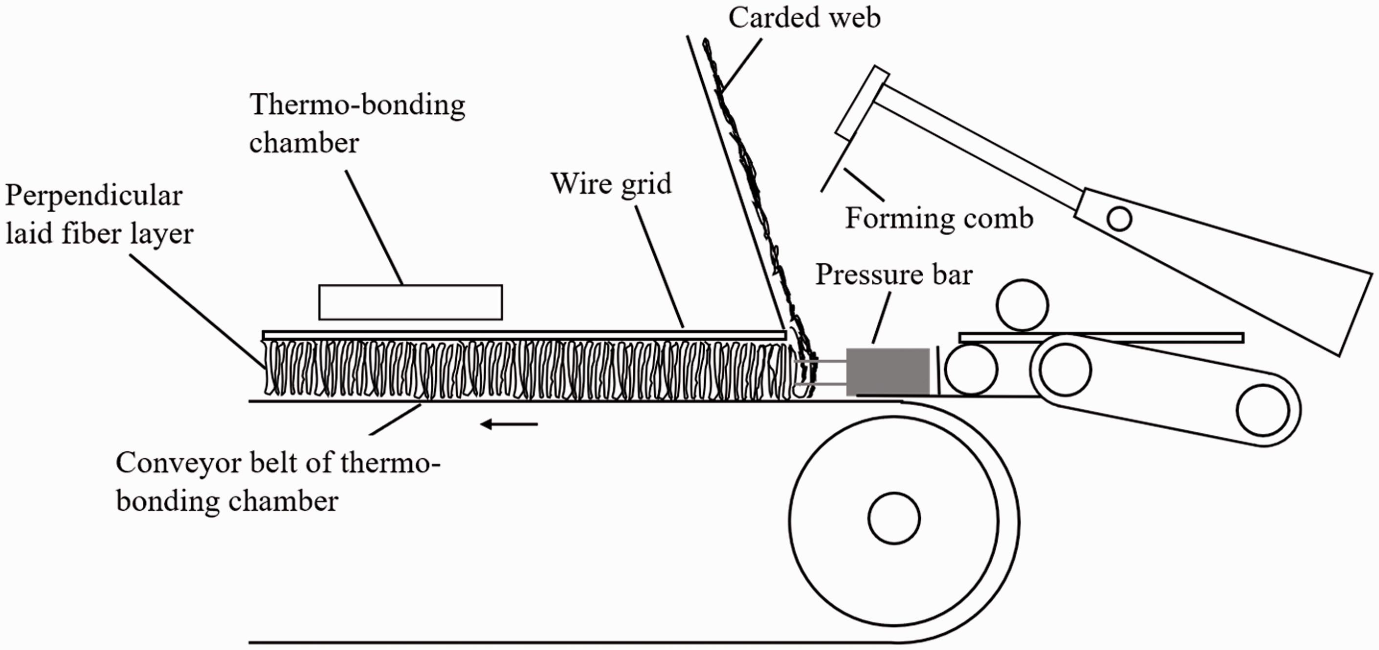
The significant fiber orientation is in the thickness direction as shown in Figure 2. In the prepared Struto nonwoven fabric, the measured angle of fiber orientation-fabric plane is 87.26°. It is a pronounced z-directional fold orientation, which is approximately perpendicular to the fabric plane. Since the ability of a fabric to keep thickness after repeated and long-term loading significantly depends on the positions of fibers in the fabrics, Struto nonwoven fabric with vertical fiber position provides a large amount of capacity to absorb heat and considerably increased resistance to deformation and a high level of recovery after loading. These properties enable it to be an excellent thermal insulation material and thus widely used as thermal insulators to deal with various heat transfer problems. Fiber orientation in Struto nonwoven.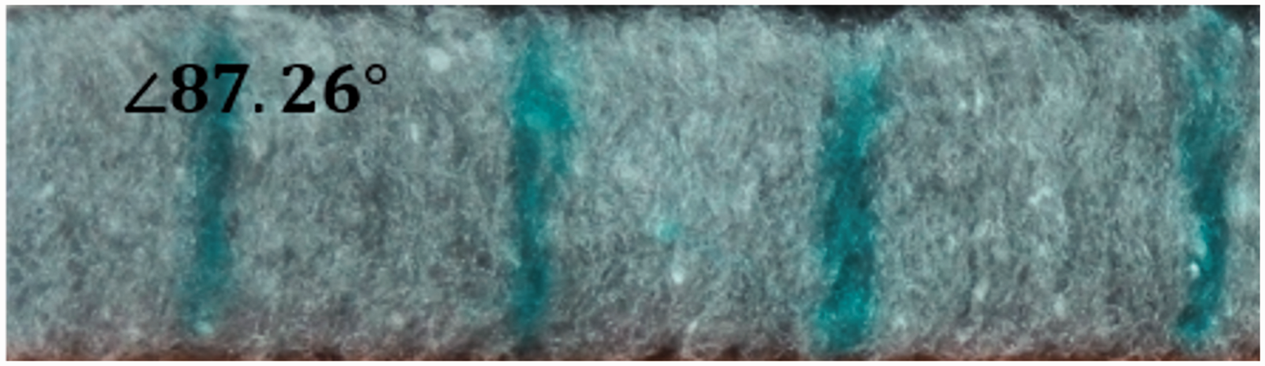
The Struto nonwoven fabric was treated by a commercial pulsed CO2 laser system GFK Marcatex FLEXI-150. The laser system is composed by a CO2 laser, a computer software, an automatic control and a laser mechanics. The laser head moves line by line to remove certain materials as the laser beam vaporizes the fibers. By controlling the parameters such as duty circle, pixel time and resolution, the laser treatment could create perforations through the nonwoven fabric according to the resolution dot of a designed graphic image. In this work, the dot pattern was designed in grey scale by Photoshop CS4 graphic design software as shown in Figure 3(a). The generated wavelength of laser beam was set at 10.6 µm and the input voltage was 100 V. The duty circle used was 50%, and pixel time was 50 μs. The image of the Struto nonwoven fabric after laser treatment is shown in Figure 3(b). Each perforation has totally the same dimension, and all the perforations are uniformly distributed on the Struto nonwoven fabric. Dot pattern for laser treatment: (a) Designed dot pattern and (b) Image of Struto nonwoven after laser treatment.
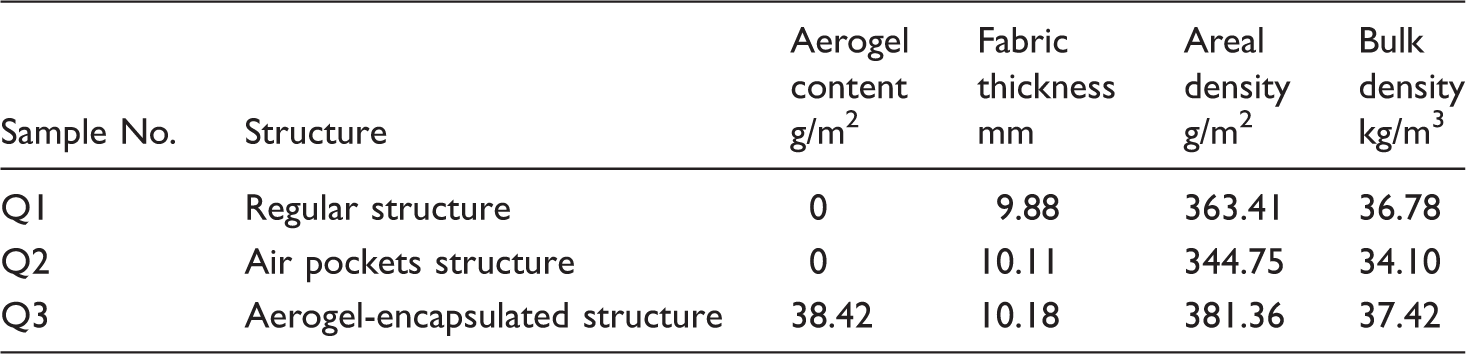
After laser treatment, a spun-melt PET fabric with thickness 0.25 mm and areal density 25 g/m2 was used as face layer to laminate with the Struto nonwoven. An extra soft textile adhesive film with thickness 0.10 mm, which is made by applying acrylic adhesives to polyethylene fibrous sheet, was selected as bonding material for laminating. The cross-sectional structure of the resultant three-layered fibrous material is shown in Figure 4(b). A three-layered material with encapsulated aerogel granules is prepared as well as shown in Figure 4(c). Prior to lamination of the face layer, aerogels were injected into these air pockets by a syringe, and the content of aerogels applied in each air pocket was controlled according to the scale on the syringe body. The aerogels were loosely packed in the air pockets. The uniformly distributed air pockets which were created by laser engraving ensure an even distribution of aerogels in the Struto nonwoven structure. Silica aerogel granules used in this work were purchased from Cabot aerogel Corp., and the particle size ranges from 0.1 mm to 0.7 mm. A layered material consisting of regular Struto nonwoven as shown in Figure 4(a) was fabricated for comparison. The details of the resultant materials are given in Table 1. Cross-sectional structures of the three-layered fibrous materials: (a) regular structure; (b) air pockets structure; (c) aerogel encapsulated structure. Description of samples.
Measurements of thermal behavior by convection
Experimental setup
A custom-made device was developed to carry out the measurement of thermal behavior by convection. The device was made by a subsonic wind tunnel in which an electric heating rod with a diameter of 2 cm and length of 20 cm was placed perpendicular to the airflow, a Sefram DC power supply was connected with the heating rod through a control unit, and a fan ventilator was used to adjust the velocity of the airflow. The fabric specimen to be tested has to be fixed on the heating rod. The schematic diagram is shown in Figure 5. The heating rod had a rated power of 500 W and voltage of 230 V, and the input power could be adjusted by the control unit. The fan ventilator, acting as a suction fan, supplied airflow at room temperature. Setup of the device used to measure thermal performance by convection.
The device measures real-time temperatures of the heating rod, the fabric specimen and the upstream airflow as well as the velocity of the upstream airflow. Temperatures of the heating rod and the specimen were tested by T-type copper constantan thermocouples. Two thermocouples were respectively attached on the heating rod and the fabric specimen by high-temperature RTV silicon. A thermoanemometrické sensor FVAD35TH5 was mounted in the upstream to monitor the velocity and temperature of the free stream. The uncertainty in the measurement of airflow velocity was ± 0.2 m/s. All the thermocouples and sensor were connected through ALMEMO 2590-2 A-2 datalogger to a PC device.
Experimental procedures
The fabric was cut into 20 cm × 8 cm and wrapped on the heating rod. The sample exactly covers the whole heating rod body, and the two longer edges of the sample were joined and sealed by a strip of insulating rubber tape as shown in Figure 6. Any gaps between the specimen and the heating rod were eliminated, and the compressive deformation of the specimen was controlled within an insignificant level. Image of the main testing section.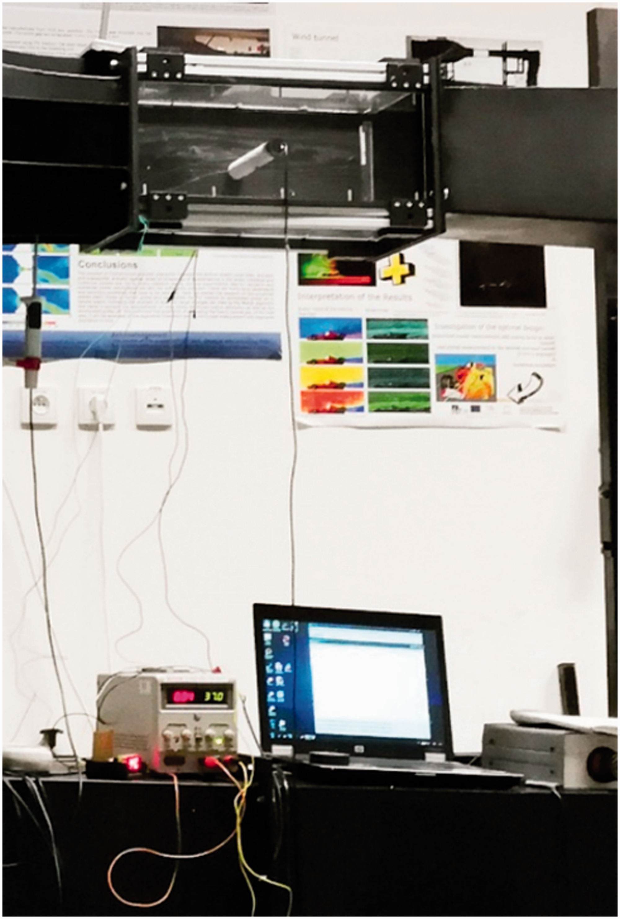
For each specimen, two types of heating conditions, preheated condition and continuous heating, were used to investigate the thermal behavior of the fibrous materials.
During the testing with preheated condition, the power supply was cut off and the fan ventilator was switched on to inlet airflow with a selected velocity when the heating rod was heated up to a specific temperature (60℃). Simultaneously, the data of real-time temperature values and airflow velocities were collected at an interval of 3.2 s. During continuous heating, the power was kept on and the airflow was allowed to be delivered in when the temperature of the heating rod reached 60℃. The voltage and current supplied from DC power to the heating rod were set at 37 V and 0.33 A. The ambient temperature was kept at 23 ± 2℃. Five airflow velocity levels, 0, 1, 5, 10 and 15 m/s were used in both conditions to study the effect of airflow velocity on thermal behavior of the fibrous materials. Each type of fabric was measured three times under both heating conditions with a selected airflow velocity. The collected real-time temperature values were averaged and plotted as a function of time.
Results and discussions
Effect of material structure on thermal behaviour under preheated condition
Figure 7 illustrates the temperature-time histories of the multi-layered materials with different airflow velocities during the measurement with preheated condition. Benefited from the air pockets which entrap large amount of stagnant air inside and thus provide lower thermal conductivity of the overall structure, the multi-layered fabric with air pockets (sample Q2) generally has lower initial temperature in comparison with regular fabric Q1. Among the three structures, the multi-layered fabric with encapsulated aerogels (sample Q3) exhibits the lowest surface temperature. This is due to the lowest heat transfer rate contributed by the component of aerogel granules. The excited gas molecules that are entering the interconnected pore structure of aerogels collide with the solid bone of the aerogels and transfer their energy to the surface, reducing the gaseous movement thus limiting the gaseous thermal conductivity of silica aerogel [27]. Temperature–time histories of the multilayered materials with different airflow velocities during the measurement with preheated condition.
At airflow velocity 0 m/s, the surface temperatures of the three fabrics are all gently decreasing, and the decreasing rate varies with sample structures. This is attributed to the fact that heat flow is continuously conducted from the fabric to the ambient air as a result of temperature gradients, and this heat transfer rate is determined by the thermal characteristics of the overall structure. The more air pockets and aerogels present in the sample, the lower the heat transfer rate of the overall structure, and thus the slower the fabric temperature drops. This further proved the better thermal insulation ability of materials with air pockets and aerogels. It can be concluded that aerogels are effective to improve thermal insulation ability and the encapsulation method for combining aerogel particles with fibrous materials is applicable. At airflow velocity over 0 m/s, all the multi-layered samples demonstrate rapid temperature drops within the first few minutes. These materials are inherently highly porous, and therefore the heat flow takes place through the porous layer by convection when the airflow penetrates the fibrous structure, resulting in obvious fabric temperature drops. The velocity component within the porous material influences the convective heat transfer rate and determines the fabric temperature. With the increase of airflow velocity, an increase in the heat transfer rates is observed.
Figure 8 shows the comparison of temperature drops from different materials. Among the three samples, the material with encapsulated aerogels is observed to have the lowest temperature drop and heat loss rate. Generally, a nonwoven fabric has porosity over 90%, its pore size ranges from 2 to 4.5 µm, which allows a bulk of air molecules to flow through [29]. In sample Q2, the number of air pockets is higher and the size of air pockets is much larger than that of sample Q1; the resistance to external airflow is lower, and therefore the heat transfer rate induced by the wind is higher. As for the fabric with encapsulated aerogels (sample Q3), since the aerogel granules have an average pore size smaller than the mean free path of air molecule, the external airflow could pass through the voids between aerogel granules but do not go through the internal structure of a single aerogel granule. Thus, aerogel granules present in a fibrous structure could prevent against the airflow stream to some degree. However, the aerogel granules in multi-layered fabric Q3 are loosely packed in the huge air pockets created by laser engraving, and they are flexible to move when the external airflow enters these pockets, enabling airflow to pass through the overall structure and causing significant temperature drops. Temperature drops of the multi-layered materials.
Analysis of variance was performed for each sample using T test method to determine whether there are any significant differences in temperature drops. Results show that there is a significance on the temperature drops of different fabrics (p < 0.05).
Effect of material structure on thermal behaviour under continuous heating
During the measurement with continuous heating, a specific electric power is supplied to the heating rod. For the system composed by the heating rod and the fabric, the heat flow generated by the heating rod was partly converted into its heat capacity, and the rest was conducted to the fabric and finally turned into heat capacity of the fabric or dissipated by air-induced convection. Temperature-time histories of the multi-layered materials and heating rod during continuous heating are presented in Figure 9. Similar to the results from the measurement with preheated condition, all the samples have rapid temperature drops within the first few minutes. After that their temperature values remain quite stable. The multi-layered fabric with encapsulated aerogel granules shows the lowest temperature values. This can be explained by two reasons. Firstly, this fabric has the lowest initial temperature because of its lowest heat transfer rate during heating up. Secondly, due to the permeability of the fabric, the air-penetration velocity through the fabric is proportional to wind speed and the heat loss increases with the increase in wind speed [30]. However, the heating rod temperature demonstrates slight fluctuations at low airflow speed (1 m/s and 5 m/s) and gentle increasing at higher airflow speed (10 m/s). These fluctuations are well consistent with the current switch. Temperature–time histories of the multi-layered materials (a) and heating rod (b) during continuous heating.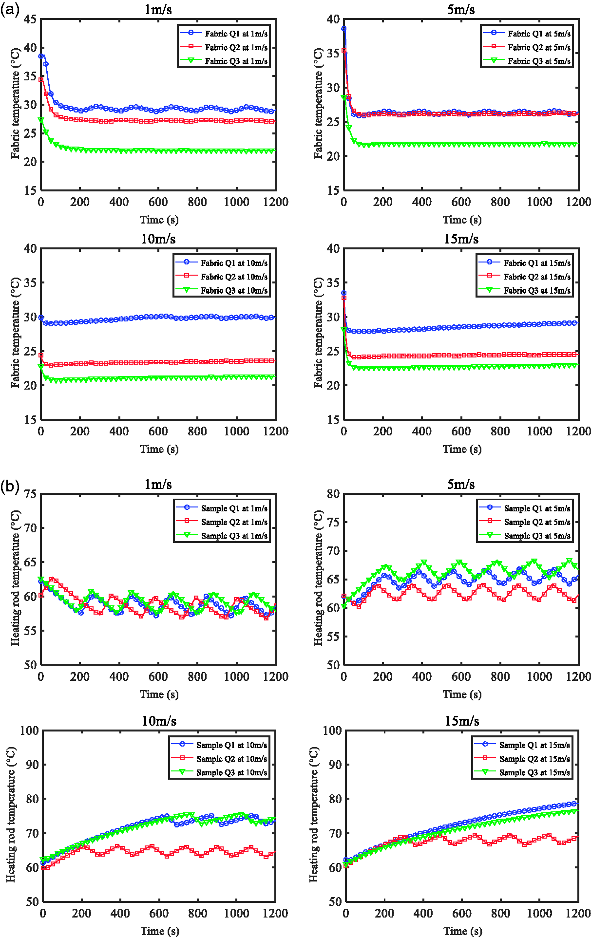
Comparison of heat transfer rate under continuous heating
In order to further compare thermal performance of the multi-layered materials with different structures, the system composed by the heating rod and the fabric can be approximately assumed to be in steady state if the temperatures of the heating rod and the fabric are fluctuating within a narrow range or showing a very gentle upslope. Typical infrared thermography images of the fabrics with air pockets and aerogels at wind speed 0 m/s clearly show the temperature differences between the fiber component and air pockets or aerogels as seen in Figure 10. But at wind speed over 1 m/s, the temperature differences become invisible due to the interference of external airflow and cooling of the system. Infrared thermography images of the multilayered fabrics: (a) sample Q2 at wind speed 0 m/s; (b) sample Q2 at wind speed 1 m/s; (c) sample Q3 at wind speed 0 m/s; (d) sample Q3 at wind speed 1 m/s.
In this case, the heat flow inlet to the system is roughly equal to the heat loss from the fibrous material under convection. Heat flow was measured by noting the current and voltage input to the heating rod. The convection heat transfer coefficient can be calculated by
The heat transfer coefficients of the multi-layered materials with different structures are illustrated in Figure 11. The layered sample Q1 exhibits lower heat transfer rates at airflow velocity 1 m/s and 5 m/s. This is due to its advantage of more fibers in the structure and higher bulk density, which could provide a barrier to prevent against airflow to some degree. With the increasing airflow velocity, the influence of airflow dominates and the advantage tends to be insignificant, resulting in remarkably increased heat transfer rates at an airflow velocity of 10 m/s and 15 m/s. The multilayered fabrics, containing air pockets and encapsulated aerogel granules, demonstrate higher heat transfer rates by convection and much less variations in this value at different airflow velocities, indicating better stability of thermal performance. Their heat transfer coefficients are both observed to increase as the airflow velocity increases. Moreover, it is notable that among these fabrics the differences of heat transfer coefficients are fairly large at airflow velocity of 1 m/s and 5 m/s, but at airflow velocity of 10 m/s and 15 m/s, the coefficients are very close. This revealed that the air pockets and encapsulated aerogels play an important role in determining the thermal behaviour of the multi-layered fibrous structure at lower airflow velocity and give less effect at higher airflow velocity.
Statistical analysis shows that the differences between regular structure and air pockets structure or aerogel-encapsulated structure are very significant (p < 0.01), and the values between air pockets and aerogel-encapsulated structure are significant (p < 0.05), indicating that the air pockets and loosely packed aerogel granules in the air pockets have significant effect on heat transfer coefficient under convection.
The Reynolds number, Re, important in predicting flow patterns in different fluid flow situations for convective heat transfer problems, is given by
The Reynolds number range for the multi-layered materials was 2582-39176. The heat transfer coefficient increases with the increase in Reynolds number as shown in Figure 12. The data fall in distinct groups depending on the structure of the multilayered material. A flat upstream trend is observed for the material containing encapsulated aerogels and the material with air pockets. For these materials, the heat transfer coefficient is significantly correlated with Reynolds number. Especially for the material with encapsulated aerogels, the correlation coefficient is 0.91, meaning that the heat transfer coefficient is directly proportional to Reynolds number. With the increasing of Reynolds number, the heat transfer rate of each material is getting closer in cross flow. Heat transfer coefficients of different multi-layered materials. Dependence of heat transfer coefficient on Reynolds number.

Conclusions
Multi-layered fibrous materials with different middle layer structures were prepared to evaluate the convective thermal behaviour with a custom-made device. A cross flow with different airflow velocities was used in the testing. It is found that the air pockets created by laser engraving lead to larger variations of temperature drops in cross flow, and aerogels encapsulated in the fibrous structure contribute to lower heat transfer rate. Analysis of the results from continuous heating showed that a remarkable increase in the heat transfer rate of the multi-layered fibrous material occurs at airflow velocity over 10 m/s. Among the three structures, the materials with air pockets and encapsulated aerogels have higher heat transfer rates in cross flow and less variations of this value at different airflow velocities. It is concluded that the different structures play an important role in determining the thermal behaviour at airflow velocity less than 5 m/s but give less effect to thermal performance at higher airflow velocity. More fundamental and numerical studies are required to further understand the convective thermal behaviour of the multi-layered materials in cross flow.
Footnotes
Declaration of conflicting interests
The author(s) declared no potential conflicts of interest with respect to the research, authorship, and/or publication of this article.
Funding
The author(s) disclosed receipt of the following financial support for the research, authorship, and/or publication of this article: This work was supported by the Ministry of Education, Youth and Sports of the Czech Republic and the European Union-European Structural and Investment Funds in the frames of Operational Program Research, Development and Education-project Hybrid Materials for Hierarchical Structures (HyHi, Reg. No. CZ.02.1.01/0.0/0.0/16_019/0000843), project “Design optimization and application of smart heat-insulating nano-layers” [LTACH-17014, 18301], project “Intelligent thermoregulatory fibers and functional textile coatings based on temperature resistant encapsulated PCM” SMARTTHERM (Project No. TF06000048) and project “Modular platform for autonomous chassis of specialized electric vehicles for freight and equipment transportation”, Reg. No. CZ.02.1.01/0.0/0.0/16_025/0007293.