
Abstract
Although electrospinning is considered a powerful and generic tool for the preparation of nanofiber webs, several issues still need to be overcome for real-world applications. Most of these problems are caused by needle-based systems, where the key factor influencing successful electrospinning is limited by the low yield of nanofibers prepared by needle-type electrospinning and the balance between the electric field force and the surface tension of the droplets. In order to solve these two issues, we use the roller type electrospinning system to prepare nanofibers. The characteristic of the system is that the roller is made of glass, and the voltage is connected to the liquid bath and the auxiliary electrode is added. We demonstrate that needle-disk electrospinning produces nanofiber with super-high throughput of 15.9 g/h, which is 177 times higher than traditional electrospinning under similar spinning conditions. Not only does it increase productivity, but also it facilitates handling and cleaning work. In addition, the auxiliary electrode can optimize the electric field and reduce the edge effect of the collecting plate. This method should help expand the range of applications for electrospun nanofiber webs in the near future.
Introduction
Electrospinning is a mature technology for preparing nanofiber structures, and many studies have addressed the preparation and application of nanofiber webs [1,2]. Although the first patent related to electrospinning was filed in 1902 [3], detailed discussion of electrospinning did not begin to appear until the early 1990s as a result of advances in nanoscience [4]. Electrospun nanofibers can utilize its unique properties (high surface-to-volume ratio, adjustable porosity of fiber structures, and the flexibility to spin into a variety of shapes and sizes) [4,5]. Electrospun nanofibers have been applied to various fields, such as drug delivery [6], tissue engineering [7,8], nanosensor [9–11], wound dressing [12,13] and energy applications [14]. Lotfian [15] et al. mentioned that in-situ measurement can be achieved through piezoelectric nanofibers.
Although electrospinning has many advantages, electrospinning is limited in practical engineering and production. Analysis of many current papers [16–24] found that the reasons for limiting the development of electrospinning technology can be summarized as: During the electrospinning process, the droplets are required to balance the surface tension and the tensile force caused by the electrostatic force. Rapid solvent evaporation accompanied by jet stretching due to electric forces and jet instabilities is ultimately responsible for the diameter, structure, and properties of the final solidified nanofibers and core–shell nanofibers [25,26]. In addition to the fact that the electrospinning process also needs to balance the rate at which the solvent evaporates and solidifies at a surface tension to form a sphere. These two reasons cause many problems in traditional single-needle electrospinning (TNE). The needle electrospinning yield is low and the needle is prone to blockage. In order to solve the problem of low output, Liu et al. [27,28] designed a needle disk electrode nozzle, which is 183 times higher than traditional electrostatic spinning under similar spinning conditions. Peng et al. [3] designed bubble models to control fiber morphology, especially nanoporous fibers. Zhao et al. [29] used the bubble model to solve the solvent evaporation problem.
Herein, we report the needle-free electrospinning technology of rotating rollers using additional auxiliary electrodes. This technique provides a facile and versatile means of preparing an electrospun nanofiber web. The 200 mm diameter roller rotates the solution from the tank to the highest point, and the polymer solution droplets can be easily stretched at DC voltage to produce a Taylor cone. The added auxiliary electrode can not only optimize the electric field, but also reduce the edge effect that occurs in the collecting plate. However, the production efficiency of the single needle electrospinning equipment is generally extremely low; the maximum total mass of the nanofiber produced per hour is not more than 300 mg [27,30]. This mode allows the production of 15.6 g of nanofibers per hour. This is 187 times higher than conventional electrostatic spinning under similar spinning conditions.
Theoretical analysis
Boundary conditions
Electrospinning is the use of polymer fluids in the formation of high-voltage electric field in the formation of polymer micro-jet, and ultimately the formation of nanofibers. Electrospinning combined with modern electromagnetics Maxwell's electrostatic equation is given as


In the static case, all physical quantities in Maxwell's equations are independent of time (
The time derivative of B in this formula (2) becomes zero, so

Electromagnetic analysis is performed at a macro level by solving Maxwell's equations under certain boundary conditions. These equations can be reduced to partial differential equations, and their successful solutions can be obtained by FEM. The basic electrostatic equation applied here is [31]


Electric field analysis
The equations for the jet follow from Newton’s Law and the conservation laws obey, namely, conservation of mass and conservation of charge. Due to the viscous dissipation of gravity and electric fields and external forcing, the entire system of jets cannot save energy. The first step in the derivation assumes that the jet is a long, slender object and then uses a perturbative expansion in the aspect ratio. This approximation method rests on expanding the relevant three-dimensional fields in a Taylor series [33]

We then substitute these extensions into the complete 3D equation and retain only the leading sequence term. Obtaining the mass conservation equation


Now we turn to the conductive field equation. The electric field of the jet can be written down due to the effective linear charge density (including free charge and polarization charge effects) of the charge Q(z) along the z-axis. To find this linear charge density, we perform the same Gauss's law twice. Therefore, it is said that Er and EZ evaluate the radial and axial components of the field in the jet on the surface of the jet, and we get [34,35]
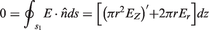
So that

An equation to predict the critical applied voltage was proposed by Taylor [33], Vc, given by

Experiment and modeling
Model building
This paper proposes a needleless electrospinning nanofiber method for adding an auxiliary electrode in space. The system mainly includes high voltage power supply, liquid tank, roller, collecting plate and auxiliary electrode (see Figure 1). The voltage V at the bottom of the receiving plate and the liquid tank is 15 Kv, and the auxiliary electrode is connected to the adjustable DC power source, and the collecting plate and the roller are separated by 20 cm. The roller uses a glass with a relatively high dielectric constant (200 mm in diameter and 10 mm in height) to reduce the interference to the electric field and to easily remove the residue. The auxiliary electrode is used to make the droplets form a Taylor cone to ensure the filament formation of the nanofibers.
Schematic diagram of electrospinning device with auxiliary electrode.
Experimental
Poly(sulfone amide) (PSA) (12.5 wt%), with average molecular weight of 150,000–200,000 was prepared. N,N-Dimethylacetamide (DMAc) with molecular weight of 87.12 g/mol was prepared. The PSA solution was prepared by mixing 12.5 wt.% PSA in DMAc by gently stirring for 2 h. All the experiments were conducted under the condition of 25℃, 40–60% RH of humidity.
The flywheel has a dielectric constant of 4 and a rotation speed of 7000 r/h.
Simulation calculation
There are many disadvantages in the traditional needle-injection electrospinning, such as low yield and easy clogging of the needle. We combine needle-type electrospinning and needle-free electrospinning with a glass-made cylinder and a system that puts the voltage into the bottom of the liquid tank. This mode not only solves the problem of needle clogging, but also greatly improves production efficiency, achieving a yield of 13.5 g per hour without sacrificing the quality of the nanofibers. It has the most significant advantage in that the spinning process now depends on the formation of many small droplets on the surface of the roller. Therefore, it is not necessary to maintain the balance of Taylor cone throughout the whole process [1,36].
Figure 2(a) shows the physical model without the auxiliary electrode. When the voltage of the liquid tank and the receiving plate is connected to 15 KV, the electric field distribution of the highest point of the roller is calculated by COMSOL (see Figure 2(b)). It is concluded that the maximum electric field at the highest point of the roller is (a) Physical model of roller spinning in COMSOL. (b) Electric field distribution at the highest point of roller. (c) The section of X-Y plane is made along the highest point of roller, and the trend of electric field is obtained. (d) Make the z-x plane section along the highest point of the roller and find the current line distribution. Nanofiber productivity of roller electrospinning and traditional single-needle electrospinning (TNE). The inserted figures are the optical images of PSA membrane piece each with an area of 1.0×1.0 cm2.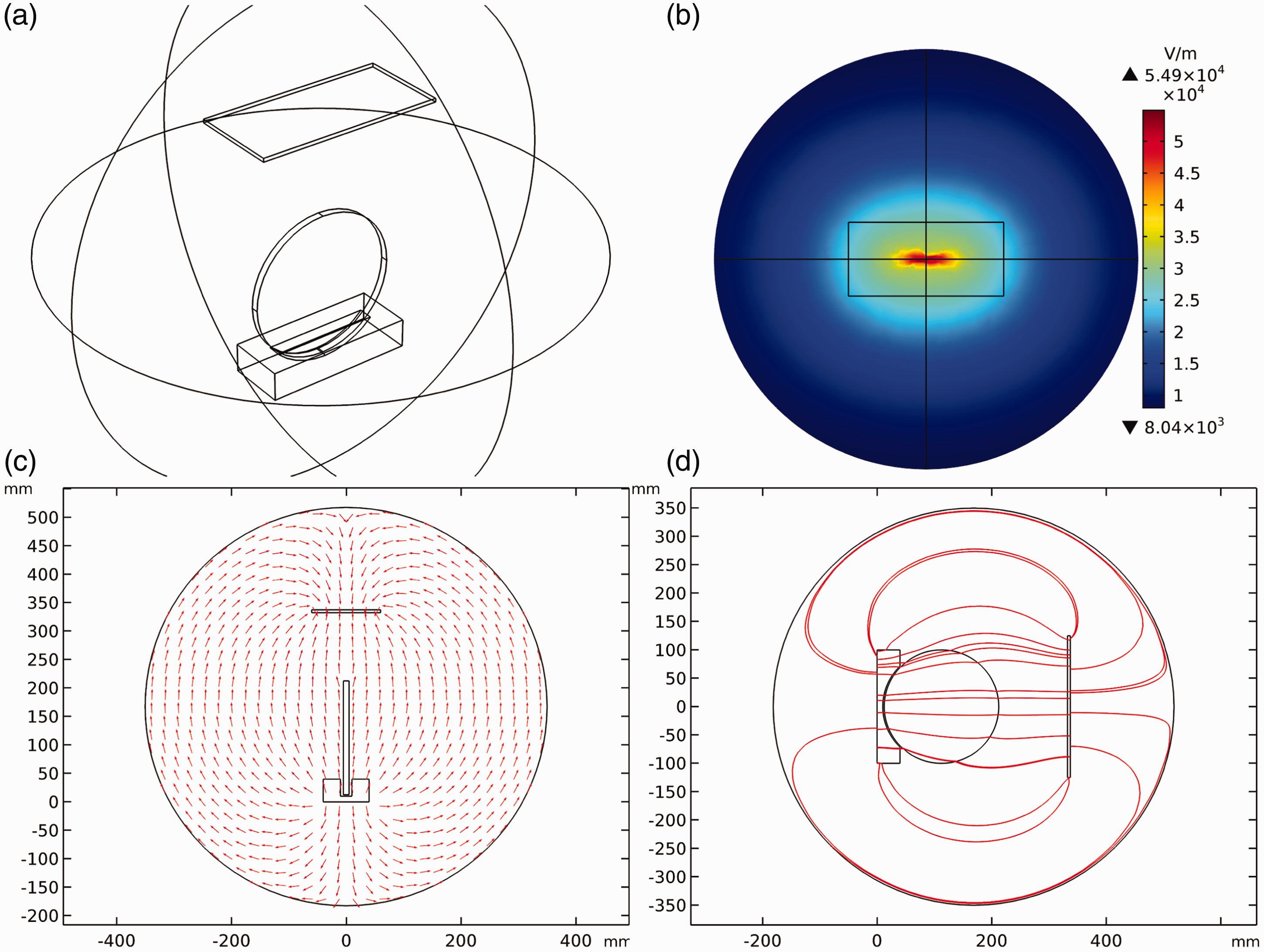

In order to improve the uniformity of the electric field in the whole filamentation region, we hope to suppress the Rayleigh instability. After continuous improvement, it was finally found that a parallel auxiliary electrode was added above the collecting plate (see Figure 4(a)). The auxiliary electrode is connected to different DC voltages, and the electric field on the auxiliary line in Figure 4(b) is obtained. When the auxiliary electrode is connected to 1000 V to 300 V, it is shown in COMSOL software that when the voltage is connected to −600 to −700 V, the electric field changes little and is more uniform (see Figure (d)). In addition, it is found that the amplitude of the electric field at the edge of the collector is also changing. When the auxiliary electrode voltage is −700 V, the electric field at the edge is relatively smooth. Although it is determined that the edge electric field uniformity is improved, we are not sure that the electric field uniformity of the part of the receiving nanofibers or even the whole collecting plate is also improved. Therefore, the auxiliary line in Figure 6(c) is made, and the relationship between the electric field size of the center line of the collecting plate and the auxiliary electrode voltage is obtained (see Figure 6(d)).
(a) COMSOL model for the auxiliary electrode. (b) Auxiliary line is made at the highest point of the roller and the collecting plate. (c) The auxiliary electrode is connected to different voltages to determine the magnitude of the electric field on the auxiliary line. Effect of auxiliary electrode voltage on the electric field at the highest point of the roller. (a) Collection panel edge line. (b) Variation of electric field with auxiliary electrode voltage in medium red line. (c) Central line in collection panel. (d) Variation of electric field with auxiliary electrode voltage in medium red line.


We can see from Figure 5 that the effect of the auxiliary electrode on the electric field at the top of the roller can be neglected. In the roller electrospinning system, there is no auxiliary electrode. The electric field generated by spinneret is 5.49 V/m. When the auxiliary electrode is connected to −1000 V to 300 V DC voltage, the electric field at the nanofiber injection increases by 20 v/m for every 100 V increase in the auxiliary electrode voltage. However, for the influence of the whole electric field, the influence rate of the auxiliary electrode voltage on the electric field at the spinning line of the roller under the simulation experiment condition is less than 0.0004.
In the above simulation, it can be known that adding auxiliary electrode has little effect on the electric field condition of spinneret. The auxiliary electrode will not cause enough electric field force to form Taylor cone. Then, we need to analyze whether the auxiliary electrode can be used to eliminate or improve the edge effect of the collector panel. The collecting plate is closest to a side of the nanofiber (Figure 6(a)). Figure 5 shows the effect of the auxiliary electrode voltage on this edge. As the voltage increases, the electric field at the edge of the collector plate decreases. It is found that the electric field of the centerline can be regarded as a fixed value when the auxiliary electrode voltage is −700 V. It is easy to conclude that under certain experimental conditions (temperature 25℃, 40–60% RH of humidity, rotating speed of 7000 r/h), when the auxiliary electrode is connected to −700 V, the whole collector plate can be seen as an isoelectric field surface, which is what we want.
Results and discussion
In the whole experiment, we not only studied the influence of auxiliary electrode voltage on the electric field of collecting plate and roller, but also made the experiment of the influence of the distance between the auxiliary electrode and collecting plate on the optimal voltage of auxiliary electrode. The distance between the auxiliary electrode and the collecting plate is 20 cm, and the optimum voltage of the auxiliary electrode is −700 V. Figure 7(a) and (d) shows the electric field distribution and the electric field of the collecting plate receiving the nanofiber plane. When the receiving distance is 25 cm and 30 cm, the optimum voltage at this time can be obtained as −900 V and −1100 V through Figure 7(b) and (c). Figure 7(e) and (f) is the electric field distribution of the plane of the collecting plate at this time. It is indicated that an increase in the distance between the collecting plate and the auxiliary electrode affects the change in the optimum voltage of the auxiliary electrode. The simulation results show that with the increase of the distance between the auxiliary electrode and the collector plate, the reverse voltage of the auxiliary electrode is also increasing, so as to ensure the uniformity of the electric field. It can provide a reference for the electric field optimization of needle-free roller electrostatic spinning and even the whole electrostatic spinning system.
When the distance between the auxiliary electrode and the collecting plate is 20 cm, 25 cm and 30 cm, the optimum voltage to reduce the edge effect is −700 V, −900 V, −1100 V, respectively. (a) Electric field line distribution. (b, c) Electric field of centerline at different voltage of auxiliary electrode. (d–f) Electric field distribution in the plane of receiving surface of collector plate.
When the gap between the collecting plate and the auxiliary electrode was 20 cm, and the auxiliary electrode was connected to the −700 V, the yield of the nanofiber was found to be increased to 15.9 g/h. The quality of the nanofibers was observed by scanning electron microscopy (Figure 8(a)) without destroying the quality of the nanofibers under the condition of improving the yield. A comparison of the single-needle electrospun nanofiber diameter range (Figure 8(b)) suggested that the roller type electrospinning can fabricate high-quality nanofiber.
(a) Scanning electron micrograph; (b) Roller-type electrospinning and TNE production of nanofiber diameter distribution map.
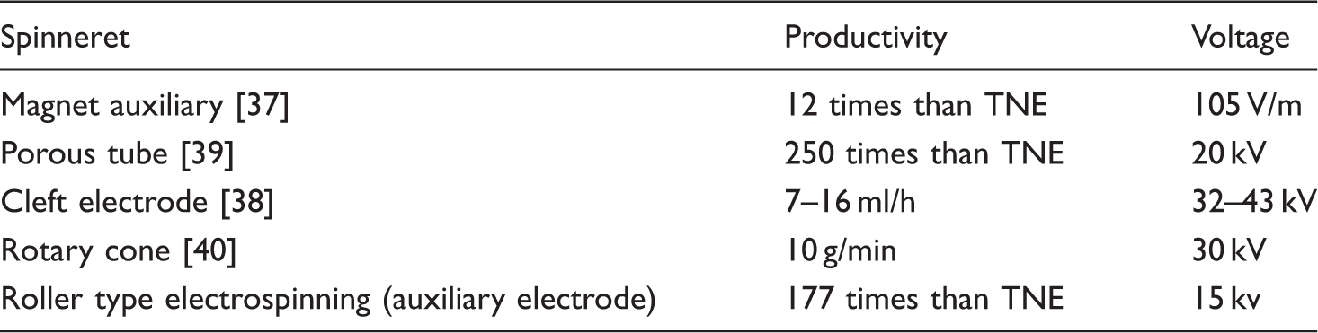
Comparison of nanofiber productivity between roller electrospinning (auxiliary electrode) and other spinning technology.
Conclusion
The use of an improved needleless roller electrospinning system is a versatile and simple technique. By changing the material of the roller and the position of the voltage connection, and finally adding the auxiliary electrode, not only the electrospinning conditions are achieved, but also the advantages of many limitations in the large-scale production of electrospinning are overcome. The technique uses a roller that not only increases the productivity of the nanofiber, but also improves the overall electric field distribution; the added auxiliary electrode optimizes the entire electric field and overcomes the edge effect of the collecting plate. This article can promote the development of needleless electrospinning and provide a reference for the electric field optimization of electrospinning devices in the future. This needleless roller electrospinning system is beneficial to fundamental research as well as practical application of nano-materials. Moreover, the system does require additional auxiliary energy to drive the spinneret, which should be a consideration in practical applications.
Footnotes
Declaration of conflicting interests
The author(s) declared no potential conflicts of interest with respect to the research, authorship, and/or publication of this article.
Funding
The author(s) disclosed receipt of the following financial support for the research, authorship, and/or publication of this article: This work was supported by the Program for Innovative Research Team in University of Tianjin (TD13-5035), National Key Technology Research and Development Program of the Ministry of Science and Technology of China (2014BAH03F01) and Tianjin Research Program of Application Foundation and Advanced Technology (15JCQNJC41800).