
Abstract
Concentrated electric field is crucial in generation of needleless electrospinning, the electric field profile together with electric field strength of the spinneret affect the needleless electrospinning performance directly. Understanding the electric field of spinneret would definitely benefit the designing and optimization of needleless electrospinning. Based on the software COMSOL Multiphysics 3.5a, 3D finite element analysis has been used to analyze the electric field profile and electric field strength of a ring spinneret for needleless electrospinning. The electric field profile shows that strong electric field concentrates on the top of the ring with intensity higher than 70 kV/cm. The electric field of ring spinneret is greatly affected by the geometry of the ring and other experimental parameters such as applied voltage and collecting distance. The electric field analysis introduced in this study will be helpful in selecting proper spinneret and scaling up the production rate of nanofibers in needleless electrospinning.
Introduction
Electrospinning has been regarded as the most prominent method to produce nanofiber [1,2], and electrospun nanofibers have shown application potentials in different areas [3]. Conventional electrospinning setup based on a needle yields nanofibers with a production rate of less than 0.1 g/h [4], which makes further application and commercialization of nanofibers impossible. Multiple needles/channels have also been applied in electrospinning so as to increase the production rate of nanofibers [5–8]. However, strong charge repulsion between neighboring polymer jets and unevenly deposited nanofibers with broader diameter range confine the further application of this method. Besides, clogging of the needles/channels may happen during the spinning process which will make the production process unsuccessful. Needleless electrospinning setups have been reported to increase the production rate of nanofibers [9–11]. A typical needleless electrospinning process is illustrated in Figure 1. Instead of using needle, a ring is used as sample needleless spinneret, and a polymer solution bath in which the spinneret is partly immersed is used to feed polymer solution onto the surface of the spinneret. A plate collector is applied to collect nanofiber when high voltage (supplied by the power supply) is applied between the spinneret and collector. Needleless electrospinning shows great potential in enhancing the production rate of nanofibers as numeral polymer jets were generated at the same time and uniform nanofibers were produced in most cases.
Schematic illustration of needleless electrospinning from a ring coil.
The generation of multiple jets in needleless electrospinning could be ascribed to electrically amplified liquid waves [12]. For a one-dimensional approximation of the fluid surface, the wavelength λ, which determine the distance between neighboring jets, can be expressed as:
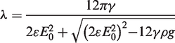
In order to understand the mechanism of electrospinning, efforts have been put on the modeling of the electric field and the spinning process [13–16]. However, most researchers paid attention to the needle-based electrospinning setup, few research works on needleless electrospinning modeling/simulation have been reported. For a three-dimensional (3D) needleless electrospinning setup, the geometry of the spinneret greatly influences the distribution of the electric field intensity profile thus affecting the electrospinning process and fiber properties [17]. It has been difficult to measure the electric field intensity of an electrospinning setup directly due to the high voltage involved.
Finite element method (FEM) is a numerical technique for finding approximate solutions of partial differential equations (PDEs), which is used to solve a wide range of physical and engineering PDE problems. It provides an alternative method to analyze the electric field profile in electrospinning. Since the practical dimensions and material properties are considered in the FEM calculation, it enables us to visualize the electric field intensity profile and to understand how this profile may be influenced by spinneret geometry as well as material characteristics. In this study, the electric field intensity profile of a ring was modeled using 3D finite element analysis software COMSOL Multiphysics 3.5a. The electric field intensity was then calculated from the profiles. This study would benefit the design and development of needleless electrospinning in which the spinneret is a crucial factor to determine the quality of the as-spun nanofiber and production rate.
Simulation theory
Electromagnetic analysis on a macroscopic level is performed through solving Maxwell’s equations under certain boundary conditions. These equations can be ascribed into PDEs and their successful solutions can be obtained via FEM. The basic electrostatics equation applied here is [18]:

The sub-domain settings and boundary settings are as follows.
The constitutive relationships describe the macroscopic properties of the medium. It is
Process for calculating electric field intensity profile. (a) Ring geometry setup by Solidworks; (b) graphic view of the complete setup constructed in COMSOL; (c) mesh view; (d) calculated electric field intensity profile.

Three boundary conditions are defined to solve the equation. The first one is electric-potential boundary condition that specifies the voltage at a boundary. Here, the boundary of solution bottom plane was defined as the value of V0 to provide electric power for the system.

The ground boundary condition is another boundary condition, which is a special case of the previous one but specifying zero potential. The boundary of infinite and the collector were set as ground boundary.

Modelling process
Figure 2 illustrates the typical process for analysis of electric field in ring electrospinning setup (as shown in Figure 1). The ring spinneret was first defined using SOLIDWORKS (Figure 2a). A bi-interface was used to transfer the defined geometry into the COMSOL interface, and other parts such as the plate collector (24 cm long, 15 cm wide and 5 mm thick) and polymer bath (24 cm in length, 10 cm in width and 4 cm in height) could then be drew directly in COMSOL. The graphic view of the setup is shown in Figure 2(b). After setting the sub-domain and boundary, the meshing process can be performed and the resultant view is shown in Figure 2(c). Finally, the electric field intensity profile can be solved as shown in Figure 2(d).
Depending on the purpose, the resultant electric field profile can be obtained from either a cross-section slice plot or a cross-section line plot, as shown in Figure 3. A cross-section slice can be drawn in the calculated profile as shown in Figure 3(a), and the resultant electric field profile is obtained separately, as shown in Figure 3(b-b′). Alternatively, a cross-section line can be drawn arbitrarily to show the electric field intensity along that line. Most specifically, cross-section line can be set through the surface of the ring at the axial direction (Figure 3c) and from the spinneret to the collector at the spinning direction (Figure 3e), respectively. The results show the electric field intensity distribution of the setup at the axial direction (Figure 3d) and along the spinning direction (Figure 3f), respectively.
Electric field intensity profile. (a) Cross-section slice; (b) in a plane; (b′) magnified view of the ring; (c) and (d) line plot in axial direction; (e) and (f) line plot along the spinning direction.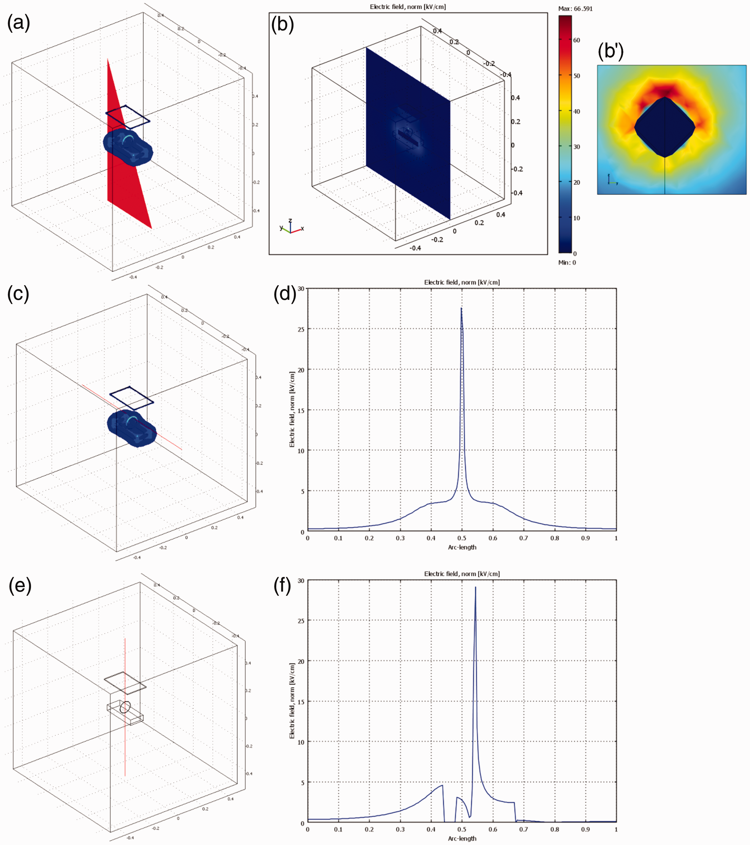
Results and discussion
Electric field profile
When a spinneret is connected with a high voltage, electric charges distribute on its surface and concentrate on the edge area that has a high curvature. With the accumulation of electric charges, a high electric field is formed on the surface. For this consideration, a ring structure would probably be very efficient in concentrating electric field. Figure 4 shows the electric field profiles/intensity of a ring coil needleless electrospinning, in which the diameters of the ring and the ring wire were set as 8 cm and 2 mm, respectively. High electric field intensity is just formed on the surface of the ring (Figure 4a), and only the top half part of the ring shows very high electric field according to the magnified view in Figure 4(b). The strongest electric field appears on the very top of the ring. Because of the small radius of curvature of the ring wire, charges tend to distribute on the narrow surface of the top ring area. In a very wide area, the ring shows electric field intensity higher than 50 kV/cm, as indicated by the red area in Figure 4(b). The ring bottom and the polymer solution show very low electric field strength. Considering the critical electric field intensity for needleless electrospinning is 5 kV/cm [17], ring coil concentrates electric field much more efficiently.
Electric field profiles of a ring spinneret: (a) overview; (b) magnified view of the ring area. Electric field intensity: (c) 3D view of electric field intensity; (d) along the axial direction of the ring; (e) along the surface of the ring; (f) along the spinning direction. (Applied voltage 60 kV, collecting distance 13 cm.)
The electric field intensity profile of the ring is shown in Figure 4(c–f). The 3D view of the surface electric field intensity (Figure 4c) shows that high electric field intensity is formed around the ring surface with the highest intensity value appearing at 90° of the ring angle θ (Figure 4d). From the axial direction, a very sharp peak is formed along the axial direction of the ring and the intensity peak is higher than 70 kV/cm. Figure 4(e) shows the intensity along the surface of the ring with different ring angles. It increases almost linearly from the surface of bath to the top of the ring with a peak at 90° (top of the ring). Figure 4(f) shows the intensity from the ring center to the collector (along the spinning way). The electric intensity increases to its peak on the ring surface and drops suddenly to almost zero along the spinning way.
Effect of applied voltage
Figure 5(a-d) shows the electric field profiles under different applied voltages. With an increase in the applied voltage, the electric field intensity along the top of the ring is strengthened gradually, as evidenced in the change of the color of the surface of the ring in the profiles.
Electric field profiles of ring spinneret under different applied voltages: (a) 40 kV; (b) 50 kV; (c) 60 kV; (d) 70 kV. Electric field intensity comparison: (e) along the axial direction; (f) along the spinning direction. (Collecting distance 13 cm.)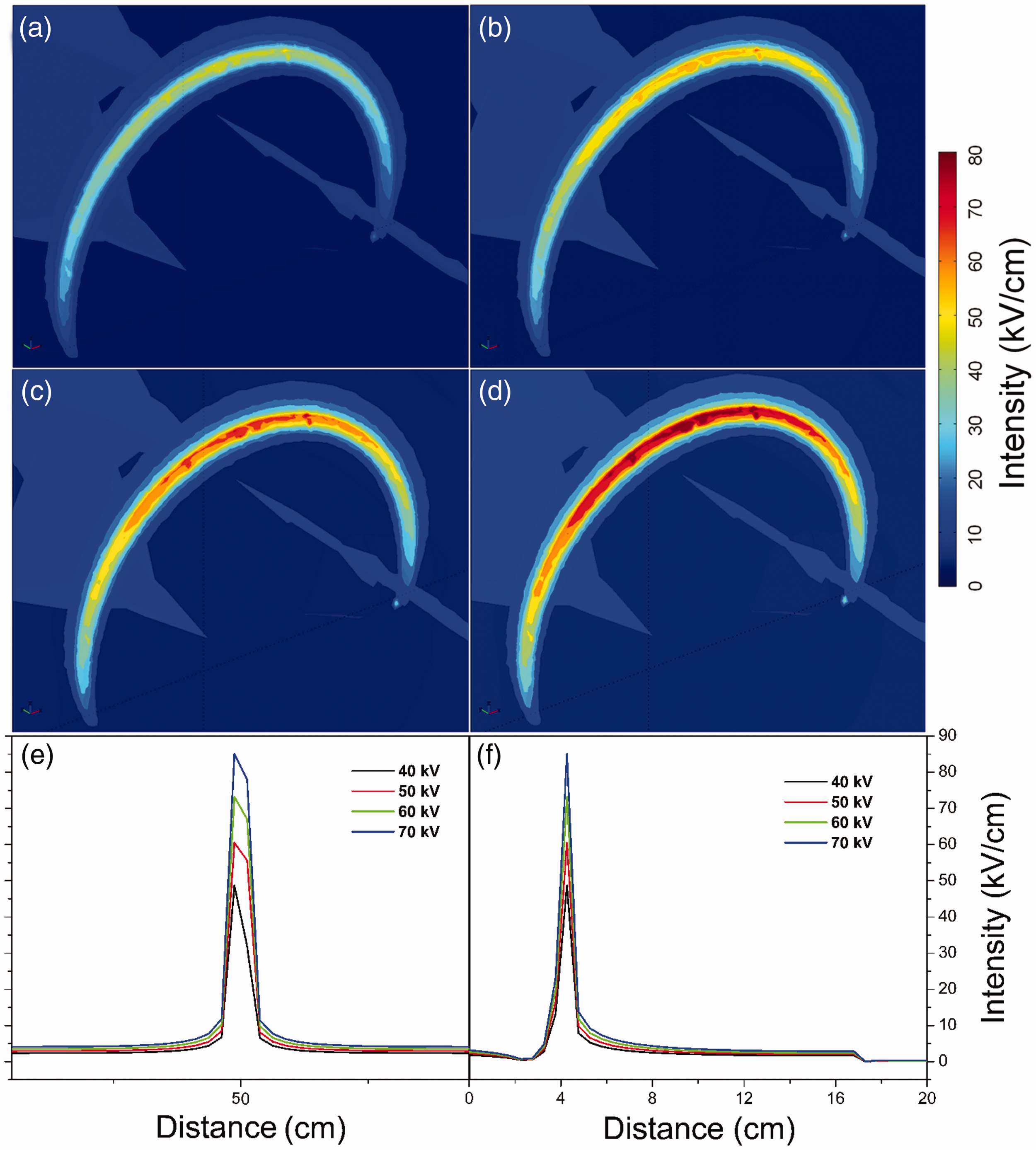
Figure 5(e–f) shows the electric field intensity along the axial and the spinning direction under different applied voltages. The peak value, which stands by the strongest intensity, increases greatly with the increase of applied voltage. When the applied voltage is 40 kV, a strong electric field forms on the top half part of the ring with electric field intensity around 40 kV/cm. With the increase of the applied voltage, the color of the top surface of the ring changes from dark yellow to light red, suggesting an increase in the electric field intensity to as high as 60 kV/cm according to the scale bar. At 70 kV, a very wide red area with an intensity of over 70 kV/cm is formed on the ring surface. Therefore, increase of applied voltage not only strengthens the electric field but also widens the area of high electric field intensity on the ring surface.
Considering the generation of nanofibers from electrospinning is greatly dependent on the electric field of the spinneret, it can be concluded that increase of applied voltage in needleless electrospinning from a ring coil not only attenuates the as-spun fiber diameter to make the fibers more uniform, but also enhances the production rate as more polymer jets can be generated owing to the widened area of highly concentrated electric field. Experiments on needleless electrospinning from a ring coil showed that the mean diameter of nanofibers decreased from 275.5 nm to 232.6 nm with standard deviation reduced from ±100 to ±88.2 when the applied voltage increased from 50 kV to 65 kV. At the same time, the production rate increased from 2.2 g/h to 5.4 g/h. Similar to traditional electrospinning, the applied voltage cannot be increased to unlimited level as ‘corona discharge’ happens under extremely high applied voltage. According to experimental investigation, the applied voltage is not suggested to be over 70 kV so as to prevent the electrospinning from ‘corona discharge’.
Effect of collecting distance
Figure 6 shows the electric field intensity of the ring along the axial and the spinning direction with different collecting distances. When the collecting distance changes from 19 cm to 10 cm, the intensity increases from around 65 kV/cm to about 75 kV/cm. It is hopeful that decrease of collecting distance would increase the production rate and improve fiber uniformity due to the concentration of electric field. However, too short a collecting distance might incur ‘corona discharge’ between the spinneret and collector which hampers the spinning process. It seems that further increase of the collecting distance might not affect the electric field much. However, too long a collecting distance is not practical since most fibers will not be able to deposit onto the collector after the whipping process of electrospinning. An optimal collecting distance in experimental was found to be 13 cm.
Electric field intensity comparison of ring spinneret under different collecting distances: (a) along the axial direction; (b) along the spinning direction. (Applied voltage 60 kV.)
Effect of wire diameter of the ring
Figure 7(a-d) shows the electric field profiles of the ring spinneret with different wire diameters. With the increase of wire diameter, the area of concentrated electric field becomes wider. However, the electric field strength declines gradually at the same time. As the electric charges tend to concentrate on the surface of high curvature, the small diameter ring shows stronger electric field intensity under the same applied voltage. Figure 7(e,f) shows the electric field intensity of the ring along the axial and the spinning direction. The intensity of the top of the ring decreases rapidly with the increase of the wire diameter.
Electric field intensity of ring spinneret with different wire diameters: (a) 2 mm; (b) 4 mm; (c) 8 mm; (d) 16 mm. Electric field intensity comparison: (e) along the axial direction; (f) along the spinning direction. (Applied voltage 60 kV, collecting distance 13 cm.)
It seems that increase of the area of the spinneret will benefit the production rate of nanofibers in needleless electrospinning. However, the number of polymer jets produced per unit area is greatly determined by the electric field intensity of that area, which means increase of the area of spinneret with electric field weakening may not contribute to further increase of the production rate. At the same time, the uniformity of the as-spun nanofibers will not be as good as that from stronger electric field as coarser fibers may be produced from low concentrated electric field. Experimental investigation from tubular wire coil has proved that increase of wire diameter will not enhance production rate as the spinnable area of spinneret is not increased, the mean diameter and standard deviation of which increases at the same time [19]. It could be estimated that similar trend will be found in ring coil electrospinning.
Effect of ring diameter
Figure 8 shows the electric field profiles of the ring with different diameters. The electric field intensity decreases as the diameter decreases, as seen from the color difference and the intensity values in Figure 8(d). When the ring diameter increases, the ring is more isolated from the polymer solution, and the electric field profile of the ring is very different compared to that of the polymer solution. As seen from Figure 8, when the ring diameter is 2 cm, the electric field intensity is weaker than that of 8 cm. When the ring diameter is very small, say 2 cm, the ring, with half of which immersed into the polymer bath, can be regarded as the ridge from the surface of polymer bath, and thus the polymer bath will affect the electric field concentration on the ring. It is quite evident that the increase of the ring diameter will concentrate the electric field to a higher lever and the spinnable area of the spinneret increases, the production rate of nanofibers will be enhanced greatly accordingly. The as-spun nanofibers will be more uniform as the electrostatic force is increased due to the stronger electric field formed.
Electric field intensity of ring spinneret with different ring diameters: (a) 8 cm; (b) 4 cm; (c) 2 cm. Electric field intensity comparison: (d) along the axial direction; (e) along the spinning direction. (Applied voltage 60 kV, collecting distance 13 cm.)
Conclusions
The electric field of needleless electrospinning from a ring coil has been successfully modeled using Comsol Multiphysics to understand the theory of electrospinning and benefit further development on mass production of nanofibers. The electric field profile shows that strong electric field concentrates along the surface of the ring with intensity higher than 70 kV/cm on the very top of the ring. Electric field intensity increases almost linearly along the ring surface from the polymer bath to the top of the ring with a peak at 90° (top of the ring). Increase of applied voltage results in higher electric field intensity together with wider area of strong electric field. Electric field intensity decreases to some extent with the increase of collecting distance. The production rate will be enhanced and fiber uniformity will be improved due to the concentration of electric field by either increase of applied voltage or decrease of collecting distance to a rational level before ‘corona discharge’ happens. Stronger electric field can be achieved when smaller wire is applied for the ring. Larger ring diameter also concentrates the electric field as the spinneret becomes more isolated from the polymer bath. Combined with experimental investigation, the optimal parameters were found to be applied voltage 60 kV, collecting distance 13 cm, wire diameter 2 mm and ring diameter 8 cm.
Footnotes
Funding
Funding supports from National Natural Science Foundation of China (Grant No. 51103109), Education Bureau of Hubei Province, China (Grant No. D20121710), Natural Science Foundation of Hubei Province, China (Project No. 2012FFB04606) and Wuhan Textile University are greatly appreciated.