
Abstract
This study reports on the improvements in the electromagnetic interference shielding effectiveness of unidirectional carbon fiber-epoxy composites as a results of stitching with conductive and nonconductive threads. Unidirectional carbon fiber laminates stitched with copper, titanium, Kevlar metallic, Kevlar 10 and Dyneema T90 threads were manufactured using vacuum assisted resin infusion process. Representative samples from each laminate were tested in directions normal and axial to the fiber direction using rectangular waveguide. Experimental results showed that composites with improved shielding effectiveness in both directions were produced. For example, stitching with copper doubled the shielding effectiveness in the axial direction when compared to the unstitched laminate. In addition, composite stitched with Dyneema exhibited the most balanced increase in the shielding effectiveness in both axial and normal directions (91.5% and 17.3%, respectively) compared to the unstitched laminate. The shielding mechanism of the composites was mainly reflection.
Keywords
Introduction
According to the aviation regulations, all portable electronic devices should be turned off on-board especially during takeoff to protect the aircraft sensitive electronic systems from electromagnetic interference (EMI) [1]. Recently, the concern of protecting aircrafts’ electronic systems from EMI has increased extensively due to many reasons. First, the rapid increase of using electronic devices by the passengers. Second, the considerable amount of electronic and electrical systems on-board that are needed to operate and control the aircraft. Third, the high sensitivity of these electronic devices to the large electromagnetic fields caused by the high-intensity radiated fields (HIRF) that emanate from high-powered radio and television frequency transmitters, radar and satellite uplink transmitters, and large microwave communications systems. Fourth, the disturbance and degradation in the aircraft navigation and communication signals due to the EMI, and finally, the use of variety of composite materials in aircraft structures which are susceptible to EMI and lack the electromagnetic shielding capabilities [2–5].
The sources of EMI in modern aircrafts can be divided into three major categories: the on-board electronic-based systems known as avionics, the passengers portable electronic and electrical devices and the external EMI from lightning strikes and HIRF [3,4,6,7]. Hence, there is a high demand for attenuating the EMI via shielding mechanisms to avoid corrupting and disturbing the aircraft avionics signals (navigation and communication signals) especially from devices with similar frequencies. Researchers have reported three major shielding mechanisms to attenuate EMI, namely: reflection (R), absorption (A) and multiple reflections (MR) [6,8,9]. Reflection mechanism requires the EMI shield to be electrically conductive to carry mobile charges such as electrons to interact with the EM radiation. However, absorption requires the shield material to have electric or magnetic dipoles to interact with the EM waves. This can be achieved by using a material with high values of dielectric constant and/or magnetic permeability. The absorption loss is proportional to the frequency and shield thickness and it is a function of the product of (σr.μr), where σr and μr are the electrical conductivity and the magnetic permeability of the material relative to copper and air, respectively [2,6]. On the other hand, reflection loss decreases with increasing frequency and it is a function of the ratio (σr/μr). Finally, MR is the third EMI shielding mechanism where large surface areas should be involved to guarantee the MR inside the shielding material. It should be mentioned that the MR effect can be neglected when the thickness of the shield is larger than the skin depth δ [10,11]. The skin depth is the distance through which the amplitude of the electric field decays to e(−1) from its value at the surface of the material, and it equals (1/alpha) where alpha is called the attenuation constant in Np/m.
Metals are excellent shielding materials, but they are heavy and environmentally unstable. It is well known that lightweight and environmentally stable materials are important requirements in aircraft structures and enclosures for avionics electronics, thus, fiber reinforced polymer (FRP) composites are more preferred for these applications. However, FRPs lack EMI shielding properties due to the dielectric nature of the polymer matrix or the dielectric nature of the used reinforcement such as glass and Kevlar. Consequently, it is necessary to reinforce the polymers with materials with excellent EMI shielding properties such as carbon fibers or conductive fillers [12–17].
Among all types of FRPs, there is a growing interest in investigating the electromagnetic interference shielding effectiveness (EMI-SE) of carbon fiber reinforced polymer (CFRP) composites for aerospace and electronic applications due to the attractive electrical and mechanical properties of carbon fibers [3,8,18–22]. Modern types of aircrafts are made of CFRP to act as a shield to reduce radio reception and transmission range especially from radar system in the X-band frequency range (8.0–12.0 GHz). Chung reported on the EMI shielding effectiveness in the (1–2) GHz frequency range of polyethersulfone (PES)–matrix composites with different reinforcement materials [8]. A composite with 20% volume fraction (Vol) of 10 µm diameter carbon fibers showed EMI-SE of 19 dB. Whereas, composites with 20% Vol of 1.6 µm-dia Steel fibers and 20% Vol of 20 µm-dia Ni fibers showed 42 dB and 5 dB EMI-SE, respectively. Rea et al. showed that carbon fiber composites with different stacking sequence can provide high levels of EMI-SE over the X and S bands comparable with that of aluminum alloys [3]. In addition, several modifications were made to the FRPs to improve their shielding effectiveness. For example, non-conductive fabric layers of FRPs such as cotton and glass were knitted with conductive wires such as copper or nickel, and conductive wires such as stainless steel and copper were knitted together to investigate the effect of these conductive fillers on the EMI-SE of the composites at different frequency ranges [23–31]. These studies showed that SE depends on the amount of knitted wires, the fiber and conductive wire orientations, stitch density and fabric structures. In another attempt, the effect of coating the fabrics or the surface of the composites on the EMI-SE was investigated [12,32]. Lately, incorporating nanomaterials such as carbon nanotubes (CNT) in polymer matrix to form what is called conductive polymer nanocomposites (CPNC) have enabled researchers to create composite materials with improved EMI-SE properties for electronics, aerospace and automotive applications [10,33,34]. On the other hand, conductive fillers were used to improve the shielding properties of polymer matrix by providing higher surface area which is believed to provide better shielding characteristics [12,28,30,31].
Approach
It has been reported in previous research studies that the conductivity of the UD-CFRP composites is higher along the fiber direction compared to the transverse and through the thickness directions at which the composite show lossy dielectric characteristics [18,35–37]. In addition, it was proved that carbon fiber is better than the dielectric polymer matrix for electromagnetic shielding because carbon fibers act as excellent conductors along the fibers direction compared to the dielectric polymer matrix. Moreover, it was found that the electromagnetic field is linearly polarized in the rectangular waveguide with TE mode. When the carbon fibers in the CFRP are oriented parallel to the E-field, they behave as good conductors, whereas in the transverse and through the thickness directions the CFRP acts as a lossy dielectric material with a finite conductivity.
Knitting unidirectional CFRP composites with Kevlar, Vectran, Dyneema and many other types of threads has been studied extensively to improve their interlaminar fracture toughness and low velocity impact capabilities [38–44]. Knitting was extensively studied even though it is well known that the inclusion of stitching does not come without compromise. Stitching dry fabrics adds an extra manufacturing step, extra cost, a potential increase in weight and extra resin pockets around the 3D architecture created. The needle piercing the fabric could fracture in plane fibers even though this effect is minor. However, stitching is recommended when improving the delamination resistance of the FRP is a requirement. The studied stitching threads were limited to non-conductive materials, even though it is well known that embedding conductive materials in FRP composites has the advantage of creating multifunctional composites with excellent EMI-SE and mechanical capabilities. In the case of knitted composites, authors believe that they can achieve remarkable enhancement in the shielding effectiveness in all composite directions (axial, transverse and though the thickness) due to compressing the carbon fibers and creating conductive paths in all the three directions.
Having this been said, the idea of this research emerged from two concepts: the well-known role of stitching fiber-reinforced polymers in resisting delamination (improving the interlaminar fracture toughness) and the improved electrical conductivity and EMI-SE of FRP composites when embedding conductive fillers. We believe that combining these two concepts will yield a multifunctional composite with improved mechanical and electromagnetic properties. Therefore, this research aims to investigate the role of stitching unidirectional carbon fiber composite with conductive (copper and titanium) and nonconductive (Kevlar and Dyneema) threads on their electromagnetic shielding characteristics. To achieve this purpose, stitched and unstitched composite laminates were manufactured by vacuum assisted resin infusion process. EMI-SE tests were carried out on these composites in both axial and normal directions using a rectangular waveguide setup and a network analyzer. The overall shielding effectiveness was calculated for each composite type using the measured scattering parameters. Finally, the transmissivity, absorptivity and reflectivity were calculated for the composite to determine the major shielding mechanism.
Experimental program
Materials
The types of stitching materials and their properties and suppliers.

Composites preparation
The carbon fiber composite laminates in this study were made of 10 plies of UD carbon fabrics. In order to study the effect of the stitching threads and fiber orientation on the electromagnetic shielding effectiveness of the composite, two patterns of the composite laminates were prepared as shown in Figure 1. Stitched laminates were prepared and called pattern 1, whereas wrapped laminates were prepared and called pattern 2. The types of threads used for stitching and wrapping the carbon fabrics in their dry form were Kevlar, Kevlar metallic, Dyneema, Copper and Titanium. The fibers stacking sequence in patterns (1 and 2) was [0°]10. In pattern 1, the threads were stitched through the thickness in a lock stitch pattern and were aligned in a direction transverse to the UD fiber direction as shown in Figures 1 and 2. In pattern 2, the threads were wrapped (twisted) around the 10 layers of the carbon fibers in their dry form in a direction transverse to the UD fiber direction without stitching them through the thickness. Figure 2 shows that the spacing between the threads was 5 mm, whereas the stitching pitch was approximately 3.6 mm. It should be noted that the X axis is along the fiber direction, Y axis is transverse to the fiber direction and Z axis is through the thickness of the laminate.
Schematic illustration showing 3D view (left) and top view (right) of (a) pattern 1 and (b) pattern 2 with the axis system, where the X-axis is along the fiber direction, Y-axis is perpendicular (transverse) to the fiber direction and Z-axis is through the thickness. (a) Top view of the stitched composite specimen showing the directions of the carbon fibers with respect to the stitching. (b) Cross-sectional micrograph (side view) of the stitched composite showing the lock stitch pattern and (c) SEM image of a fractured composite specimen.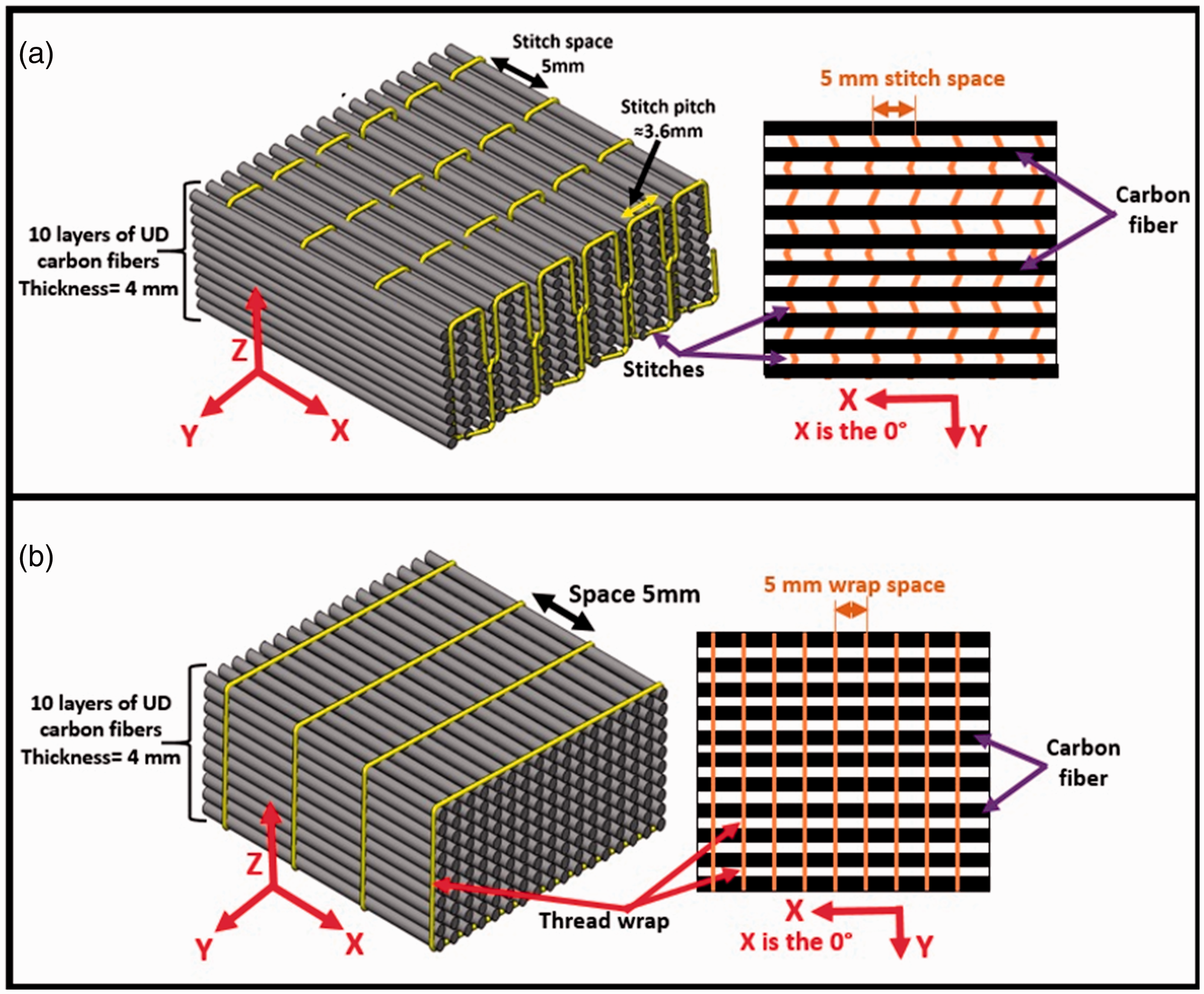

A total of 11 laminates were prepared using the vacuum assisted resin transfer molding (VARTM) process shown in Figure 3; five stitched laminates, five wrapped laminates and one unstitched (pristine) laminate as control composite for comparison purposes. In the VARTM process, the epoxy mixture was prepared in a weight ratio of 100:30 and then infused through the dry fabrics to form composite with approximately 60% fiber weight fraction and 40% epoxy weight fraction. The curing process was conducted under a vacuum level of −27 inHg and at room temperature overnight. The laminates’ thicknesses ranged from a minimum of 3.6 mm for the stitched with Kevlar 10 laminate to a maximum of 4.2 mm for the unstitched laminate. More details on the VARTM process can be found in literature [43,44].
Schematic illustration of the vacuum assisted resin transfer molding process (side view).
Electromagnetic interference shielding effectiveness measurements
Samples with the dimensions 3 cm × 3 cm were cut from the laminates using a wet diamond saw to be tested for electromagnetic shielding properties. The EMI SE was determined using the S-parameters in the X-band frequency range (8.0–12.0 GHz) using the setup shown in Figure 4. The setup consisted of E5071CENA series 300 kHz–20 GHz Network Analyzer connected to SIVERS lab – Philips PM-7328-X rectangular waveguide via coaxial cables. The specimen was sandwiched between the two parts of the waveguide, and then the scattering parameters (S-parameters) (S11, S12, S21, S22) were recorded for each sample in the X-band frequency range.
(a) Electromagnetic shielding effectiveness (EMI SE) measurement setup. (b) The dimensions of the rectangular waveguide.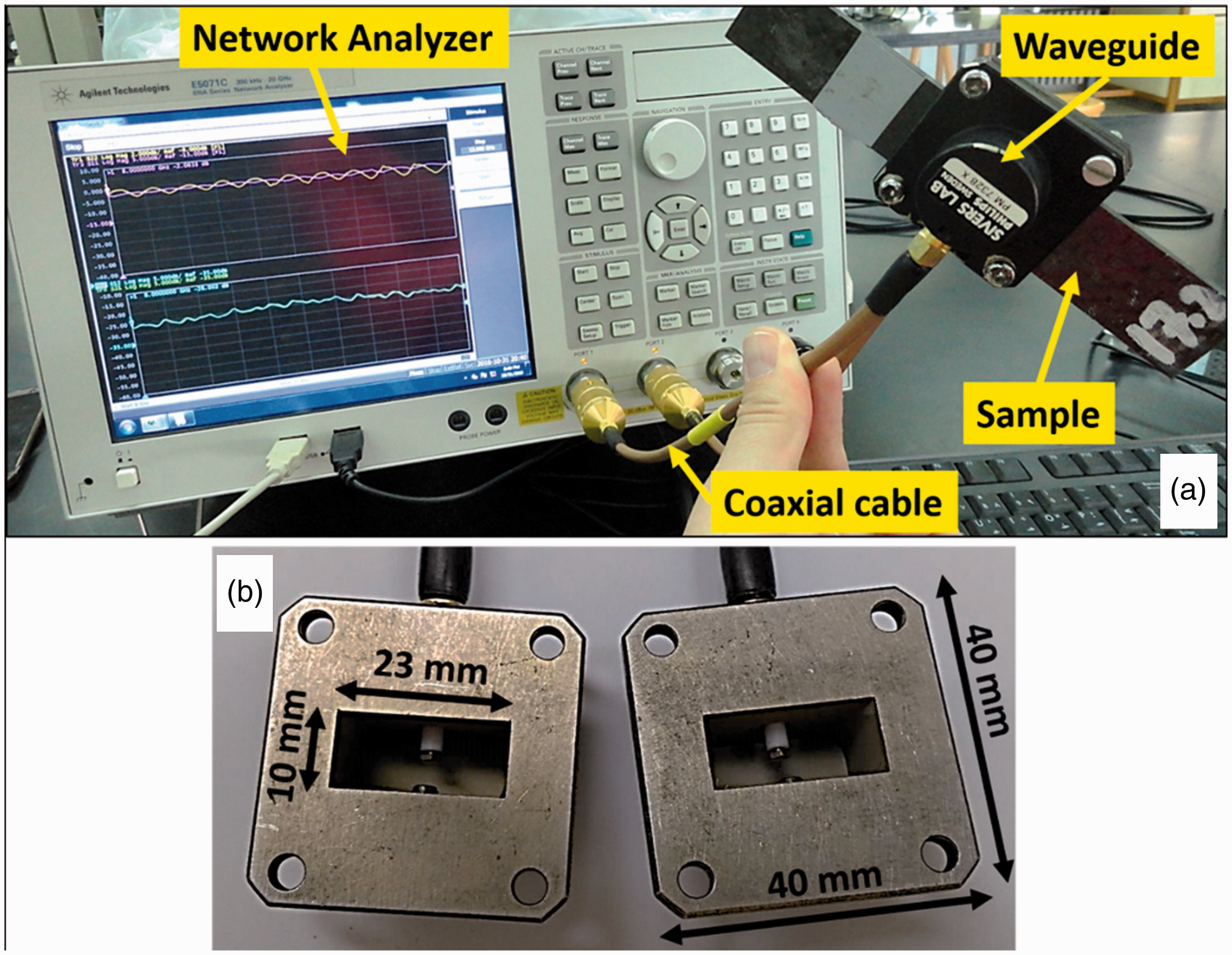
At least five samples from each pattern with stitching thread were tested in two orientations, namely the axial and normal directions with respect to the waveguide as shown in Figure 5. In the axial direction, the UD fibers were aligned parallel to the long side of the waveguide whereas in the normal direction the UD fibers were aligned parallel to the short side of the waveguide. A total of 120 samples representing each pattern, stitching thread and orientations (axial and normal) were tested.
(a, b) Schematic illustrations showing the direction of the carbon fibers and the stitches with respect to the waveguide; the axial direction is when the UD-CFs are parallel to the long side of the waveguide and the normal direction is when the UD-CFs are perpendicular to the long side of the waveguide. (c) 3D and front view illustrations of the rectangular waveguide with the TE mode showing the directions of the electrical and magnetic fields.
Using the S-parameters, the total EMI SE for each sample at each frequency, the reflection loss (shielding by reflection) SER, the absorption loss (shielding by absorption) SEA, the reflectivity (R), the transmissivity (T) and the absorptivity (A) were calculated using equations (1)–(7) [15,33,34,45–47].


Results and discussion
Overall EMI shielding
Overall EMI shielding effectiveness of pattern 1
The EMI SE was calculated for each tested sample in the 8–12 GHz frequency range using equation (1) where frequency increment of 0.02 GHz was used in the network analyzer. Figure 6 shows the EMI SE curves of representative pattern 1 composite specimens in the axial direction. It is observed that composites stitched with conductive (Ti and Cu), nonconductive (Kevlar and Dyneema) and semi-conductive (Kevlar metallic) threads exhibit remarkable increase in the SE compared to the unstitched composite over the investigated frequency range. In addition, the figure shows that SE of the unstitched composite is almost independent of the frequency in the 8–11 GHz range, but it shows a slight increase between 11 GHz and 12 GHz. However, stitched composites exhibit fluctuating SE in the 8–9 GHz range followed by a slight increase in the 9–12 GHz frequency range. Similar curves with similar trends were generated for each sample from each pattern in both the axial and normal directions.
Electromagnetic interference shielding effectiveness (EMI SE) of samples representing unstitched and stitched composites from pattern 1 in the axial direction.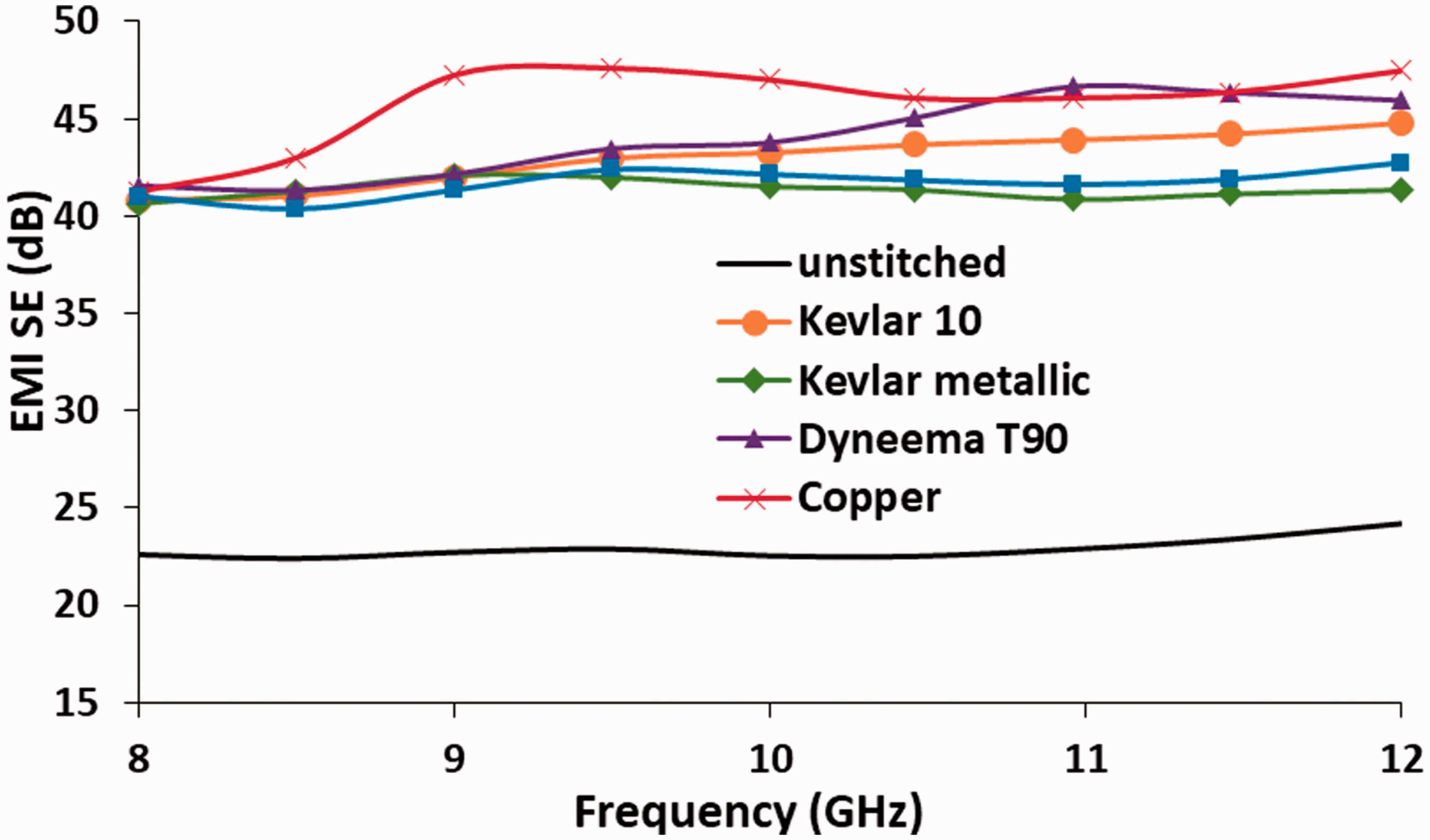
Figure 7 shows the relationship between the frequency and the absorption SEA and reflection SER losses of both stitched and unstitched composites. Figure 7(a) shows that the absorption loss SEA increases with increasing the frequency whereas Figure 7(b) shows that the reflection loss SER decreases with increasing the frequency. This is due to the increase in the material’s absorptivity of the electromagnetic waves with increasing frequency and the decrease in the material’s reflectivity with increasing the frequency. In addition, Figure 7(a) shows that composites stitched with dielectric materials (Kevlar 10 and Dyneema T90) experience (higher slope=more increase) higher increase in the absorption loss with increasing the frequency, whereas Figure 7(b) shows that composites stitched with metallic threads experience higher slope in the reflection loss with increasing the frequency. This is because the wavelength of the electromagnetic wave decreases with increasing the frequency and becomes closer to the fiber size, hence it is easier to be absorbed than reflected. The findings regarding the absorption and reflection losses dependency on the frequency in this study conform with what was discussed in previous research studies [2,8,20,26,46].
(a) Absorption loss SEA and (b) reflection loss SER of samples representing composites from pattern 1 in the axial direction.
Average EMI SE values with the standard deviations (SD) in the axial and normal directions of the composites from patterns 1 and 2.

EMI SE: electromagnetic interference shielding effectiveness.
In the case of composites from pattern 1 in the normal direction, there is no significant effect of stitching on the SE. This is because the carbon fibers are aligned with the polarization direction of the electric field in the TE mode (fibers parallel to the short wall of the waveguide) which produces an almost perfect reflector |S11|≈1 and |S12|≈0 and increases the overall conductivity of the composite. However, composites stitched with copper and titanium have slightly lower SE because stitching dry fabrics with these threads creates large resin pockets around the 3D architecture. The needle piercing the fabrics could create spaces in a direction parallel to the UD fibers which can be filled with resin as shown in Figure 8. These longitudinal resin pockets, which are dielectric defects, lower the conductivity along the fiber directions and block the flow of electrical charges. Consequently, stitched composites from pattern 1 have improved EMI shielding in all directions related to the UD-CF (X, Y and Z).
SEM images of surfaces of fractured composites stitched with copper and titanium threads showing the UD fibers, the metallic thread and the emerged resin pockets, which are parallel to the fiber direction.
Overall EMI shielding effectiveness of pattern 2
Table 2 shows the overall SE of pattern 2 composites in the axial and normal directions. It is clear that there is no significant increase in the SE in both normal and axial directions when wrapping the composite’s carbon fibers with different types of threads except those wrapped with copper and titanium (compared to the unstitched composite). Wrapping the composite’s fibers with copper and titanium results in 27.6% and 18.6% increase in the axial SE, whereas it results in 15.75% and 10.4% increase in the normal SE, respectively. The behavior of pattern 2 can be interpreted as follows: the wrapping threads do not compress the fibers together as in pattern 1, therefore, there is no increase in the overall conductivity of the composite except in the case of using conductive threads like Cu and Ti. When wrapping the CFs with copper and titanium, they are aligned with the polarization direction of the electric field; hence, they increase the conductivity of the composite and the SE accordingly. In the normal direction, there is no effect at all of the wrapping threads except when wrapping with copper and titanium because of the same reasons mentioned earlier and because the dominant effect on the shielding is the alignment of the UD fibers with the polarization direction of the electric field as discussed above.
Absorptivity and reflectivity
Average values of: absolute values of scattering parameters (S11) reflection and (S12) transmission coefficients, absorptivity (A), reflectivity (R) and transmissivity (T) of composites from pattern 1 in the axial direction.

Conclusions
The effect of stitching unidirectional carbon fiber-epoxy composites with conductive and nonconductive threads on their EMI-SE was investigated experimentally. Laminates stitched with various materials (Kevlar, Dyneema, copper, titanium and Kevlar metallic) were manufactured using VARTM process. A rectangular waveguide was used to measure the electromagnetic shielding effectiveness of these laminates in the 8.0–12.0 GHz frequency range at different orientations. Stitched and wrapped CFRP composites with the aforementioned threads were prepared. Results showed that composites with improved electromagnetic shielding effectiveness in directions normal and axial to the fiber direction were prepared. Composite stitched with copper showed the highest improvement in the SE in the axial and direction, whereas composite stitched with Kevlar 10 showed the highest improvement in the SE in the normal direction. However, wrapping the composite with the threads did not reveal any significant improvement in the SE except in the case of wrapping with conductive threads (copper and titanium). Results revealed that even composites stitched with nonconductive threads exhibited improved shielding effectiveness compared to unstitched composites. This is because the key point in improving the SE was achieved by pressing the fibers together to create conductive channels through the thickness direction regardless the method of pressing (e.g. by increasing the molding pressure during processing). In this study, the author investigated the effect of stitching on improving the SE.
Footnotes
Declaration of conflicting interests
The author(s) declared no potential conflicts of interest with respect to the research, authorship, and/or publication of this article.
Funding
The author(s) disclosed receipt of the following financial support for the research, authorship, and/or publication of this article: This work was financially supported by the Deanship of Research – Jordan University of Science and Technology, Irbid – Jordan, research grants with the numbers (184/2015) and (345/2016).