
Abstract
The demand for multifunctional requirements in aerospace, military, automobile, sports, and energy applications has encouraged the investigation of new conductive composite fibers. This study focuses on the development of Vapor-grown carbon nanofibers (VGCNFs) filled Polyvinylidene Fluoride (PVDF) composite fibers. Polyvinylidene fluoride (PVDF) reinforced with (1, 3, 5, and 8 wt.%) carbon nanofibers were produced as a masterbatch. The production of PVDF and PVDF/CNF composite fibers have been done successfully by using melt spinning processing technique. Conductive woven fabrics were produced with composite fibers on handloom machines to measure electromagnetic interference (EMI) shielding efficiency. Tensile strength of fibers increased with increase in CNF loading up to 3%. The tensile strength displayed a decrease of 5% and 8% CNF loading. Electromagnetic shielding effectiveness (EMSE) of woven fabrics with composite fibers were tested by using the coaxial transmission line method for planar materials standard that is based on ASTM D 4935-10. The electromagnetic shielding effectiveness of woven fabric which is consist of conductive composite fibers were increased with increasing CNFs loading and amount of fabric layers. It can be seen that the woven fabrics displayed between 2–10 dB and 2–4 dB EMSE values in the 15–600 MHz and 600–3000 MHz-frequency range, respectively. Nevertheless, it was observed that conductive filler content, dispersion, and network formation within the composite fibers were highly influent on the electromagnetic shielding effectiveness performance of the structures.
Keywords
Introduction
Recently, there has been a tremendous effort spent on developing nanofiber/polymer composites for a variety of industrial applications. 1 One of the biggest reasons for these great attempts is the desire to obtain more functional and efficient materials compared to traditional microfiber/polymer composites. Therefore, utilizing nanofibers as filler materials for polymer composite production has been widely investigated. 2
The number of electronic devices and the amount of equipment ranging from televisions to mobile phones and wireless communication systems, have dramatically increased all over the world. The advent of wireless technology has seen an exponential increase in the use of electromagnetic wave-based devices and architectures such as personal communication equipment, wireless networks among others, resulting in significant electromagnetic interference (EMI) phenomena in both civilian and military applications. While it is of little doubt that these advances have enhanced the standard of living for people worldwide, nevertheless these devices emit electromagnetic radiation.3,4 Long term exposure to acute electromagnetic radiation can have harmful effects on human tissue and can interfere with specific bio-electronic devices such as pacemakers. 3 Electromagnetic shielding materials are thus necessary to protect human health and electronic devices against the harmful effects of these electromagnetic waves. 4
Conventional reinforced polymer composites have displayed potential for their use in aerospace, military, automobile, sports, and energy applications; however, the demand for multifunctional properties has encouraged the investigation of new materials. In recent years, numerous studies on the development of advanced polymer composites with improved electrical, mechanical, thermal, and EMI shielding properties have been conducted. 5 Composite structures with conductive fillers have a scientific interest in EMI shielding protection owing to their low cost, lightweight, flexibility, corrosive resistance, and easy processability rather than metal-based composites. 6
Composite structures with conductive fillers consist of two main components which are insulating polymer matrix and inorganic electrically conductive fillers such as carbon black, carbon nanofibers, carbon nanotubes, metal powders, etc. which exhibit many exciting features due to their resistivity change with mechanical, thermal, electrical, or chemical solicitations.5 –9 These composite structures have many useful advanced applications such as EM wave protection, sensor technology, high mechanic protection, etc. When inorganic conductive fillers compare with metal-coated or plated materials, it has limited applications in the EMI shielding because of required high filler loading and less shielding capabilities.10 –12 Shielding performance of composite structures with conductive fillers mainly depends on the amount and types of carbon fillers. 7
The mechanical properties of the composite structures deteriorate with overloading of fillers, and besides, the cost of composite structures increases with increasing of weight loading.7,12 The mechanical, thermal, and electrical properties of reinforced polymer composites improve with using carbon nanofibers (CNF). 13 The addition of various types of carbon nanotubes and nanofibers influence the crystallization kinetics and resulting morphology.14,15
Polymer composites filled with conductive inorganic fillers which are micro-sized forms and low aspect ratio particles are not commercially competitive with the polymer plating techniques in the EMI shielding market. 7 Therefore, the weakness of micro-sized conductive filler can overcome by nanostructured on high aspect ratio and highly conductive nanofillers such as vapor-grown carbon nanofibers (VGCNFs), carbon nanotubes and metal nanowires.7,16 The conductive Nano filler with the high aspect ratio have low electrical percolation threshold concentration, and the high conductivity along with the high aspect ratio ensures that these nanocomposites will have an adequate level of shielding at relatively low filler loading compared with traditional composites.7,10 The percolation threshold is the necessary amount of CNF to build initially connected conductive networks. 6 Easier processing, lowering cost, and better mechanical properties of composite structures with conductive fillers obtain with reducing the percolation threshold.8,17 The development of high-performance nanofiller/polymer composites, a homogeneous dispersion of the fillers must be achieved in the polymer matrices as well as a vital interface interaction between the polymer and the fillers to affect efficient load transfer from the polymer matrices to the VGCNFs. 9 Uniform dispersion within the polymer matrices and improved VGCNF/matrices wetting and adhesion are essential issues in the processing of nanocomposites. Therefore, conventional mixing methods which are a twin-screw extruder, high shear mixer and two-roll mill are using for preparing of composite structures with conductive fillers. 18
In this study, polyvinylidene fluoride (PVDF) has been selected as a polymer matrix due to it is suitable for electrical application compatibility. And also, Vapor-grown carbon nanofibers (VGCNFs) has been chosen as a conductive filler because of comparing with other conductive fillers, superior electrical conductivity, excellent mechanical performance contribution and low cost. Various amounts of VGCNFs have been melt into PVDF. The production of PVDF and PVDF/CNF composite fibers have been done successfully by using melt spinning processing technique. The morphology, structure, and thermal property of the composite fibers were evaluated by scanning electron microscope (SEM), Fourier transform infrared spectroscopy (FTIR), thermogravimetric analysis (TGA) and differential scanning calorimetry (DSC), respectively. The mechanical and physical tests applied to investigate the mechanical and physical properties of composite fibers. The main objective of the project, which is the properties of electromagnetic shielding effectiveness (EMSE) of woven fabrics with composite fibers was tested by using the coaxial transmission line method for planar materials.
Experimental
Materials
All materials used in the study were provided to the producers by paying their fees. One grade type of CNFs was used as a conductive filler which is graphitized VGCNF (PR-25-XT-LHT) obtained from Sigma Aldrich. The commercial textile grade of polyvinylidene fluoride (PVDF) (Solef®1000 series) purchased from Solvay Company. The characteristics of CNFs and PVDF are reported in Table 1.
The properties of VGCNFs and PVDF.

Production of CNF (carbon nanofiber)/PVDF composite fibers
Compounding of CNFs and PVDF
The VGCNFs and PVDF were mixed in a compounder with designed weight ratio, dried at 100°C for 24 h in an oven and then were extruded by a twin-screw extruder machine (Thermo Electron Corporation Prism Eurolab16). This machine consists of six heating chambers in the extruder and an automatic feeding system, as shown in Figure 1. The melt compounded polymers were cooled down to room temperature in a water bath first and then were sliced into pellets by a pelletizer. Finally, the VGCNFs/PVDF masterbatches with 1, 3, 5, and 8 wt% of VGCNFs were obtained, which looked like black granule in appearance. The masterbatches (VGCNFs/PVDF) have been prepared around 600 g for each sample. The working conditions of compounding on the twin-screw extruder machine are given in Table 2.

Compounder machine.
Working conditions of melt compounder for batch.

Production of composite conductive fibers on extruding machine
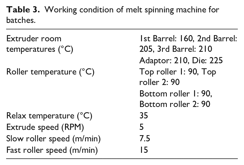
Before fibers extrusion, these masterbatches on pellet form were dried in a vacuum oven for 12 h at 80°C. The batch of PVDF monofilament fibers containing 1, 3, 5, and 8 wt% CNF was produced using the EMERSON&RENWICK machine, as shown in Figure 2. Melt-spun composite monofilament fibers were made on an average fibers count of 40 and 80 tex with a draw ratio of 1:6 and 1:10, respectively. Composite fibers properties are shown in Table 4. Working conditions of the melt extruder and fiber extrusion parameters are given in Table 3.

EMERSON&RENWICK melt spinning machine.
Working condition of melt spinning machine for batches.
Properties of composite fibers.

Production of sample woven fabrics
Ten different kinds of fabrics samples were prepared by using the handloom-weaving machine. The plain-woven pattern was chosen for the manufacturing of woven fabrics. The produced woven fabrics and their properties are shown in Figure 3 and Table 5, respectively.

Samples of woven fabrics and handloom-weaving machine.
Properties of woven fabrics.

Electromagnetic shielding efficiency and electrical properties
Electrical resistivity measurements have been done via 4-point probe system and the resistivity measurements are given in Table 4. A coaxial transmission line method specified in ASTM D4935-10 was used to test the EMSE of the woven fabrics. The specimen was prepared with a standard test size of various thicknesses. The outer ring of the sample was 133 mm in diameter. Two pieces were required to be produced for the test, one for reference and another for load testing. Various researchers have described the detailed setup and testing procedure using a plane-wave electromagnetic field in the frequency range of 15 MHz–3 GHz. A network analyzer (Rohde Schwarz, ZVL) to generate and receive the EM signals and a shielding effectiveness test fixture (Electro-Metrics, Inc., EM-2107A) were used to measure the EMSE, which was measured in decibels (dB) in this investigation. Where P1 (watts) is received power with the fabric present, and P2 (watts) is received power without the fabric present. The input power used was 0 dB, corresponding to 1 W.11,19,20,21
The shielding effectiveness of the fabric has been established using the insertion-loss procedure according to standard. This method has been involved irradiating a flat, thin sample, utilizing a coaxial transmission line with a flanged outer and an interrupted inner conductor. A reference measurement with the empty cell is required for evaluation of the shielding-effectiveness (Figure 4(b)). The reference specimen is placed between the flanges in the middle of the section, covering the inner and flanges conductors. A load measurement is performed on a solid disk shape, its diameter the same as that of the flange (Figure 4(c)). These measurements are performed on the same material with reference and the load samples. The shielding effectiveness is determined with equation 1.

(a) Setup of the electromagnetic shielding effectiveness testing apparatus; (b) and (c) specimen for reference and load respectively.
The total shielding effectiveness (

where


Results and discussion
Chemical characterization of composite fibers
FTIR analysis of the PVDF with/without CNF fiber was carried out using a Spectrum Two FT-IR Spectrometer (PerkinElmer). The most characteristic absorption peaks of polyvinylidene fluoride are clearly visible in the spectrum of pure PVDF and are as follows: The typical absorption band in the wavenumber region of 1120–1280 cm−1 is associated with the –CF2 group of the PVDF main chains. The band at the wavenumber of 1400 cm−1 is attributable to the –CH group of the PVDF in Figures 5 and 6. The appearance of the broadband between 2500 and 3500 cm−1 due to the OH vibration supports those findings.23,24

FTIR analysis of PVDF and PVDF with CNF fibers (draw ratio of 1:6).

FTIR analysis of PVDF and PVDF with CNF fibers (draw ratio of 1:10).
Thermal characterization of composite fibers
DSC analysis of the PVDF with/without CNF fiber was carried out using a DSCQ2000 system (TA Instruments). TGA analysis of PVDF with CNF fiber was carried out using TA Instruments SDT 2960 DTA-TGA. For testing, about 2.1 mg of PVDF and PVDF with CNF sample was weighed before being placed in a DSC span. These fiber samples were carefully rolled using tweezers and then sealed in aluminium crucibles. The device worked at between −50°C and 200°C under 50 ml/min N2 flow. Under a nitrogen atmosphere, the DSC test was continued by increasing 10°C/min until 200°C. In Figures 7 and 8, the results of DSC analyses are depicted. The DSC analyze shows that the pure PVDF and PVDF with CNF pellets melt in a temperature of 172.14°C.

DSC analysis of pure PVDF and PVDF with CNF fibers (draw ratio of 1:6).

DSC analysis of pure PVDF and PVDF with CNF fibers (draw ratio of 1:10).
The loading of CNF on conductive composite fibers was measured using TGA analysis. This experiment has been performed to investigate the effect of CNFs loading on the thermal degradation behavior of composite fibers under the nitrogen atmosphere. The weight loss percentage of conductive composite fibers as a function of temperature range 45°C–700°C are shown in Figures 9 and 10. The decomposition of PVDF occurs in the temperature range of 400°C–750°C with two significant mass losses observed at 450°C and 500°C. The amount of CNF remaining for each sample was calculated by subtracting the amount of PVDF remaining as follows. The residual mass left (considered as CNF wt%) was found to be 6.98%, 4.95%, 3.15%, 1.15% and 7.51%, 5.15%, 2.95%, 0.95% for 6×D and 10×D of CNF/PVDF composite fiber samples, respectively.

TGA analysis of pure PVDF and PVDF with CNF fibers (draw ratio of 1:6).

TGA analysis of pure PVDF and PVDF with CNF fibers (draw ratio of 1:10).
Rheology behavior of the composite fibers
The rheological characterization of samples was performed on a Physica MCR 61 series from Anton Paar rheometer, which imposes either the shear stress or the shear viscosity at 180°C. The behavior of composite fiber is evaluated by plotting the viscosity and shear stress versus the shear rate at the same temperatures. The shear viscosity of the solution increases with increasing filler concentration. Moreover, the shear viscosity decreases significantly with the increasing shear rate at the high filler concentrations. Therefore, shear viscosity indicates that the shear-thinning behavior of the spinning solution became more and more evident with increasing composite fibers concentration. Given a polymer solution at the low polymer concentration, it plays the dominant role in the viscosity.25,26
Considering the results obtained in the studies conducted in the literature, it is expected that the shear stress and shear viscosity values increase as the number of conductive filling increases, parallel to this, as seen in our study, the shear stress and shear viscosity values increased with the increase in the amount of conductive filling. The lack of optimum shear stress and shear viscosity values depending on the polymer negatively affect the fiber production from the polymer material. The variation of shear viscosity and shear stress of the PVDF and PVDF with four different CNF concentrations for the shear rates are shown in Figure 11. The shear stress and the shear viscosity of composite fibers increase with increasing of conductive filler (CNF) concentration in PVDF. Besides, the shear viscosity decreases significantly with increasing shear rate for all conductive filler (CNF) concentrations in PVDF. On the other hand, the shear stress increase with increasing shear rate for all CNF concentrations in PVDF. The SEM images of PVDF with various (1, 3, 5, and 8 wt%) CNF concentrations are shown in Figure 12. It was observed from SEM pictures that the additive material increased. Also, VGNFs dispersion has occurred on all good concentrations.
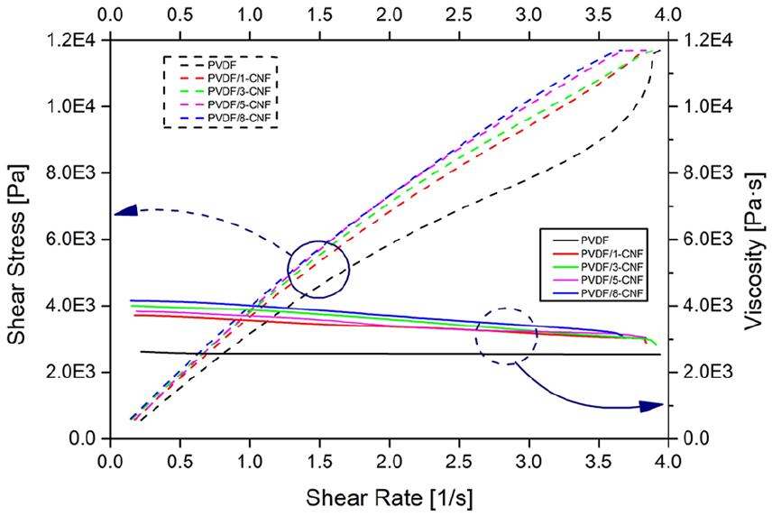
Shear stress and viscosity versus a shear rate of molten PVDF and PVDF with different CNF concentrations blend at 180°C.

The SEM images of conductive composite fibers with CNF concentrations: (a) 1 wt% CNF, (b) 3 wt% CNF, (c) 5 wt% CNF, and (d) 8 wt% CNF.
Mechanical characteristics of the composite fibers
The monofilament fiber tensile tests are carried out at Instron 4411 tensile testing device with computer control. The test length and speed are adjusted to 250 mm due to high elongation rates of the fiber and 250 mm/min, respectively. Enhancing the mechanical properties of VGCNF composites requires good dispersion and distribution of nanofibers in the polymer matrix while maintaining the aspect ratio of nanofibers. Nanofiller can be dispersed and aligned in a polymer matrix using different techniques, including melt spinning. Excellent dispersion of filler minimizes the stress concentration centers and improves the uniformity of stress distribution. 1 The comparisons of the tensile strength of fibers are shown in Figure 13. It can be seen that 1:6 drawn coded fibers displayed a higher tensile strength and strain than 1:10 drawn coded fibers in Figure 14. As expected, the tensile properties of the PVDF composite fibers with CNF increased with increasing of amounts of CNF. However, the tensile strength and strain of these fibers decreased over adding of 3 wt% CNF. As the reason for this decrease might be due to a state of poor dispersion and distribution of conductive filler (CNF) within the polymer matrix over this concentration.

Tensile strength test results of PVDF and PVDF/CNF fibers.

Tensile strain at maximum load of PVDF and PVDF/CNF fibers.
Electromagnetic shielding efficiency
The EMSE performance of fabrics with conductive composite fibers (CNF/PVDF) measured between 0.015 and 3 GHz frequency range are presented in Figures 15 and 16. It can clearly observe that the EM shielding properties of all fabrics have similar behaviors. Findings revealed that the amount and the dispersion of VGCNFs had a considerable impact on the EMSE results due to the increment in the numbers of conductive fiber network in the composites. Moreover, it was noticed that the EMSE performance of each composite increased almost cumulatively. In contrast, the content of VGCNFs increased in the structures due to the high aspect ratio triggered the conductive network formation at even very low nanofiller loading. 27 The shielding effectiveness of woven fabrics reveals that as frequency increases, EMSE values show a tendency to decrease between 0.015 and 0.6 GHz frequency range, then a tendency to rise between 0.6 and 3 GHz frequency range slightly. As expected, The EMSE values increase with the increasing amount of conductive fillers in conductive composite fibers, as seen in Figures 15 and 16. The shielding performances of the fabrics are measured in one and two layers. Therefore an increase of fabric layer, the amount of conductive materials increase (per unit area), and this increase in conductivity values leads to a higher EMSE. Moreover, as compared to each other samples consistently showed 1–2 dB higher EMSE values across the between 0.015 and 0.6 GHz frequency range. This difference became more significant at higher frequency values which is between 0.6 and 3 GHz frequency range where the difference reached nearly 3–5 dB. Besides, the woven fabrics that are produced with a draw ratio of 1:6 fibers display higher EMSE values than woven fabrics had a draw ratio of 1:10 fibers between 0.015 and 0.6 GHz frequency range. It is observed that EMSE values increase with increasing amounts of CNF.

EMSE of plain-woven one- and two-layer fabrics produced from PVDF with CNF monofilament fibers (draw ratio of 1:6).
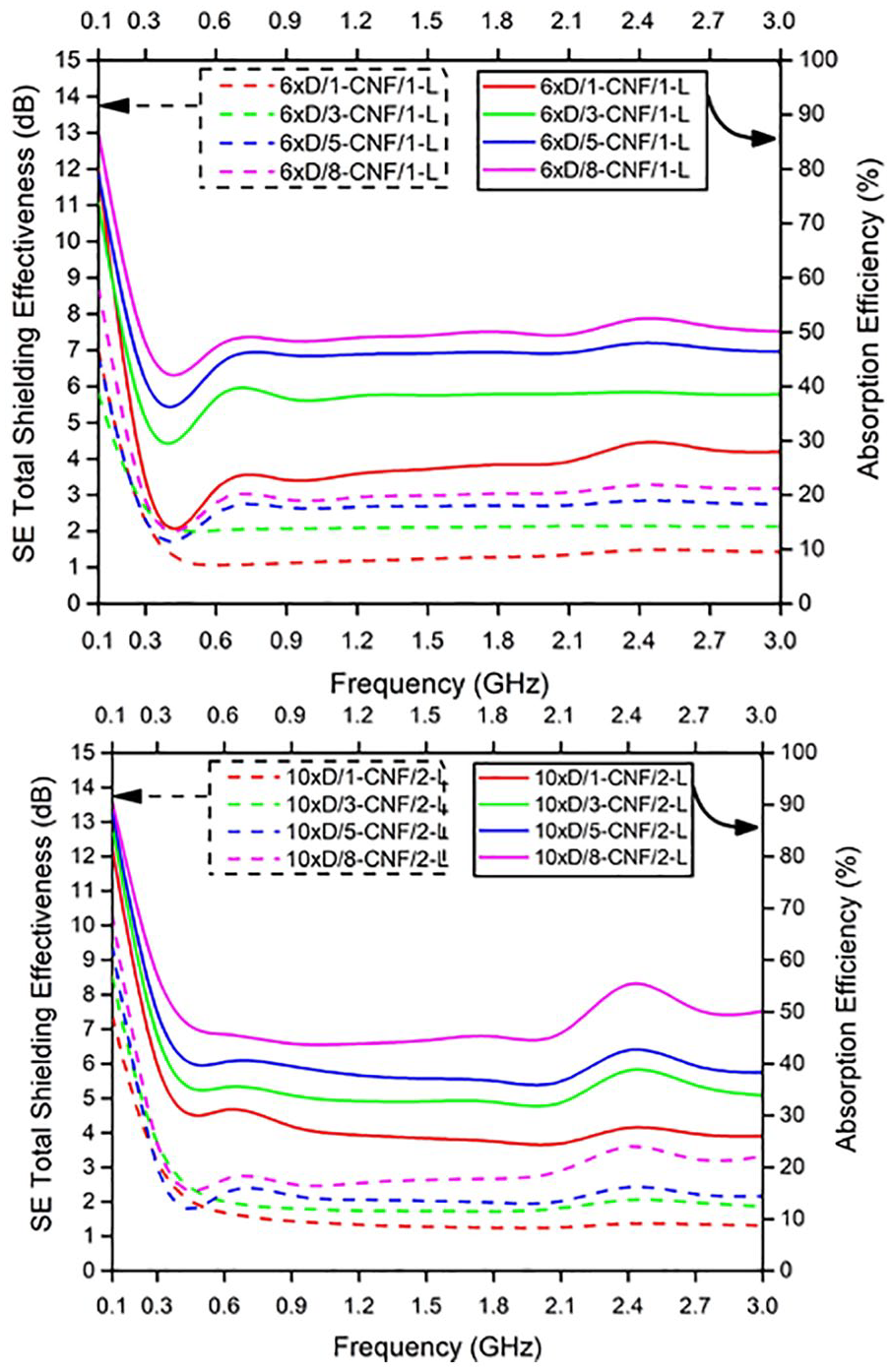
EMSE of plain-woven one- and two-layer fabrics produced from PVDF with CNF monofilament fibers (draw ratio of 1:10).
The reflection and absorption of electromagnetic waves are related to the properties of conductive fillers. For instance, CFs are defined as more absorbent materials rather than being reflective in terms of the attenuation of electromagnetic waves in significantly increasing frequencies.28 –31 Depending on the intended use, reflection and absorption performance expectations vary. Besides, higher absorption, not a scattering of exposed electromagnetic waves to the environment, will not be disclosed to the interference of frequencies. Similar results were obtained by many researchers for different kinds of conductive nanofiller materials. 32 Another reason for this result could be explained by the decrease in gaps between the fibers with increasing nanofiller loading, consequently enhancing the absorption loss. 33 The reflection and absorption behavior of the woven fabrics are shown in Figures 17 and 18. It can be observed that the reflection values observed across the measurement range showed an opposite trend to the absorption values, with the absorption values increasing and reflection values decreasing with an increase in the frequency. The reflectance values are consistently lower than absorption values for all fabrics between 0.015 and 0.6 GHz frequency range. This behaviors of fabrics with conductive composite fibers is related to the properties of the materials. As can be seen, when the reflectance values decrease, the absorption values increase. The absorption values of all fabrics decrease gradually with increases of frequency between 0.015 and 0.6 GHz frequency range. In the 0.6–3 GHz frequency range, the reflection values increase progressively with a rise in frequency.
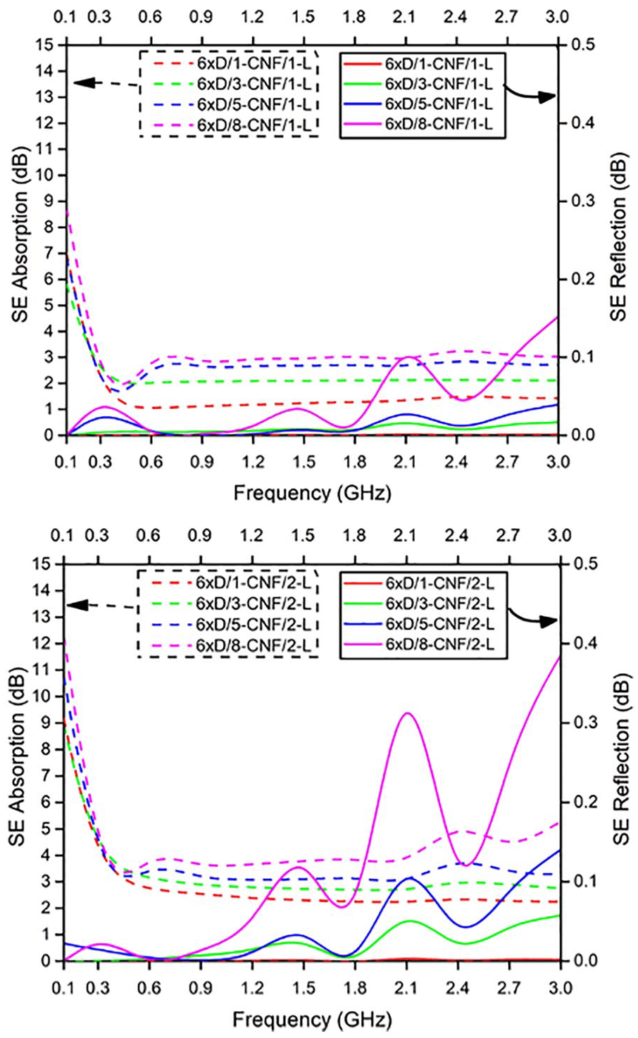
Absorption and reflection results of plain-woven one and two-layer fabrics produced from PVDF with CNF monofilament fibers (draw ratio of 1:6).

Absorption and reflection results of plain-woven one and two-layer fabrics produced from PVDF with CNF monofilament fibers (draw ratio of 1:10).
Conclusion
In this work, although some problems were encountered in manufacturing, the production of PVDF and PVDF_CNF composite fibers have been done successfully by using melt spinning processing technique. The morphology, structure, and thermal property of the composite fibers were evaluated by scanning electron microscope (SEM), Fourier transform infrared spectroscopy (FTIR), and differential scanning calorimetry (DSC), respectively. The mechanical and physical tests applied to investigate the mechanical and physical properties of composite fibers. The main objective of the project, which is properties of EMSE of woven fabrics with composite fibers was tested by using the coaxial transmission line method for planar materials standard that is based on ASTM D 4935-10. Scanning electron microscopy was used to investigate the nanocomposites dispersion of nanofiller and the adhesion between the nanofiller and polymer matrix. The general properties of composite fibers related to nanofiller (CNF) dispersion in a polymer matrix (PVDF) obtained as expected. Four different nanofiller (1%, 3%, 5%, 8%CNF) loadings have been prepared because of the limited amount of nanofiller (CNF). The tensile strength of fibers increased with increase in CNF loading up to 3%. The tensile strength displayed a decrease of 5% and 8% CNF loading. It can be seen that the woven fabrics displayed between 2–10 dB and 2–4 dB EMSE values in the 0.015–0.6 GHz and 0.6–3 GHz frequency range, respectively. It is understood that the one layer woven fabrics have higher EMSE values than the two-layer woven fabrics. For higher shielding values, the percentage of the nanofiller (CNF) in the mixture should be increased. EMSE values were evaluated, as shown in Table 6, it was observed that all fabrics shield around 80% and 70% of electromagnetic waves between 0.015–0.6 GHz and 0.6–3 GHz frequency range, respectively. When the amount of nanofiller (CNF) is increased, it is evident that many difficulties during the melt spinning process can emerge and it should be known that the cost of the production would be higher.

Footnotes
Declaration of conflicting interest
The author declared no potential conflicts of interest with respect to the research, authorship, and/or publication of this article.
Funding
The author received no financial support for the research, authorship, and/or publication of this article.