
Abstract
For structural design applications, through-thickness characteristics of reinforcement played a vital role, which is why 3D woven preforms are recommended for such applications. These characteristics are mainly dependent on the fiber and yarn positioning in reinforcement. Although research has been conducted for characterizing woven composites, special attention has not been made on weave pattern parameter which directly affects the mechanical performance of composites. In this research work, 3D orthogonal layer to layer and through thickness woven structures with different interlocking patterns have been thoroughly studied for their mechanical properties, thickness, air permeability and areal density. Natural fibers when used with biodegradable matrix find use in structural, as well as low to medium impact applications for automobiles. Jute yarn was used to produce four-layered 3D woven structures, as synthetic fibers will not give a biodegradable composite part. The focus of this study is to optimize weave pattern, which is robust in design, degradable preforms and easy to reproduce. The main objective of this research focused on the effectiveness of weaving patterns on physical and mechanical properties as well as to optimize the weave pattern for optimum performance. Grey relational analysis was used for the optimization of the robust weave pattern. The results showed that hybrid structures can be useful for improving the properties of the orthogonal layer to layer and through thickness woven structures. It was also noted that weft-way 3D woven structures can provide comparable mechanical properties with warp-way 3D woven structures.
Keywords
Introduction
Advances in the engineering of composites made an extraordinary contribution by introducing exceptionally high-performance products. Today, metals are being substituted by composites [1]. The use of composites in conventional to the hi-tech industry has motivated researchers to enhance their efforts to create high-performance composites [2]. On the other hand, textiles have proved to be versatile and attractive for composite applications [3,4]. Woven textiles can be two-dimensional (2D) or three-dimensional (3D). 2D structures cover the two perpendicular directions [5] and are frequently used in laminated composites. These structures demonstrate good in-plane properties like strength, transverse load resistance, and stiffness but they lack in out-of-plane properties [6–8], whereas, 3D woven structures used as reinforcement have capability for structural designs applications due to superior through thickness characteristics [9]. 3D woven structures are manufactured by textile process, supported by three or more yarns, oriented in three orthogonal planes [10]. These structures can be manufactured on normal 2D weaving process with an additional set of binder yarn [11]. The 3D woven structures produce flexible and impact-tolerating fabrics [12] and are used for low to medium performance applications as well as high-performance products [13] including fiber-reinforced polymer (FRP) composites. One can modify or design 3D woven structure, in which fiber/yarn can be positioned favorably in a direction likely to face high stresses [14]. Various fabric manufacturing techniques including weaving, braiding, knitting and stitching have been used to produce 3D preforms [15–18]. Among these techniques, various properties and shapes such as definite thickness, straight shape, curved and irregular shapes can be achieved easily using weaving process [15]. The woven ensemble has high orientation in their structures [19], such architecture results in structure stability and strength.
After application of multidirectional loads, while in immobile conditions, in-plane transversal stresses cause damage in transverse directions [7], whereas shear stresses cause loss of stiffness [20]. Using 3D woven structures, out-of-plane stress components can be controlled with regard to thick fabric/laminate, fatigue loading, dynamic effects, impact loads and stress concentrations [21]. Stacking depends on its orientation and the applied resin infuses these stacked layers [22]. 3D laminates are preferred in thick assemblies where high interlaminar shear stress is essentially necessary [23]. 3D textile reinforcement is economical for composites [24]. Such preforms are considered to be a structural support for mechanical and shape of finally made composites [25]. In structural composites, 3D woven structures have integrated continuous fiber assemblages devising multiaxial in-plane and out-of-plane fiber orientation [26]. Use of layer-to-layer and through thickness warp interlocks, and intentionally using 3D non-crimp woven structures have improved in-plane stiffness and strength [27]. These developments assisted manufacturers to considerably expand their use in advanced applications [28] like boats, yachts, armor backings and military vehicles body parts, structural elements, and joints of wind energy generators, load-bearing components, high-temperature-resistant, damage-tolerant engine, etc.
A multilayer fabric consists of two or more layers, linked to one another at fastening points. The numbering of layers is counted consecutively from top to bottom. 3D woven interlock preforms can be categorized as (a) 3D woven angle-interlock (through thickness interlock and layer-to-layer interlock) and (b) 3D woven orthogonal-interlock (through thickness interlock and layer-to-layer interlock) [29–31]. 3D woven interlock structures are multilayered fabrics produced by interlacing three sets of fiber tows, strands or yarn in the weaving machine. Warp and weft layers are interlocked/interlaced by the third set of yarns called binder yarns, also referred to as warp weavers because interlocking is normally achieved through warp threads. For achieving maximum mechanical properties, loom setup is critically important for 3D woven structures to reduce fiber damage during the weaving process. Effect of fiber or yarn properties on the fabric for tensile strength depends on various parameters like damage of fiber/yarn while weaving, structure, fiber/ yarn /tow (linear density), warp and weft thread density, crimp, interlacement angle, cover factor, type of weave and number of binding points between warp and weft [32].
Orthogonal multilayer interlock structures are produced in a way that warp yarns of a layer are used to bind the other layers. There is no interlacing between warp and weft yarn, as they are straight and perpendicular to each other [33]. The interlocking pattern affects the performance of 3D woven structures [34]. Orthogonal-interlocking can provide better fiber volume fraction, especially in the thickness direction when compared to angle-interlocking, while the angle-interlocking possesses better pliability and distortion capability than the orthogonal-interlocking. It is, therefore, appropriate to select orthogonal-interlock composites for better through thickness performance and angle-interlock composites for producing components with complex configurations [29]. The layer-to-layer structure shows higher fiber volume fraction as compared to through thickness structure, owing to the overlapping arrangement of binders in the thickness direction. Therefore, this is another useful parameter to improve the performance of 3D woven composites.
In general, natural fibers are preferred over synthetic fibers due to their sustainability, environmentally friendly nature, low cost and comparable specific strength. Among natural fibers, jute is preferred, as it has one of the cheapest fiber and comparable strength as compared to others [35]. The use of natural fibers has gained interest in different application areas of the composite. The specific tensile strength of bast fibers is higher [36] than E-glass, which make these more attractive for composite fabrication by researchers [37]. These also give advantage to weight and cost reduction in automotive [38].
Natural fiber reinforcement fabricated with thermoset and/or compression moulding is used for producing parts like door liners/panels, parcel shelves and boot liners [39]. Four-layered composites have a thickness approximately equal to 3–4 mm, which is mostly used for automobile interior/structural applications. The use of bridgeable and sustainable fiber, with its prospective use with the biodegradable matrix, is the objective of this work. Therefore, the use of glass, carbon or any other manmade fiber will not justify the objective of this work.
The focus of this study is to optimize weave pattern, which is robust in design, degradable preforms and easy to reproduce.
The main objective of this research focused on the effectiveness of weaving patterns on physical and mechanical properties as well as to optimize the weave pattern for optimum performance.
The developed fabrics may be used as a preform in composites for making simple geometry automobile parts and interior, etc. The mechanical properties tested are indicators of global mechanical performance of preform.
The explicit aims involved the preparation of preform on a conventional weaving loom in warp-way and weft-way and the hybridization of layer to layer and through thickness weaves.
Grey relational analysis (GRA) is a tool for improving fabric/product parameters [40]. For multi-response optimization, this method is useful [41]. Original Taguchi method is restricted to a single response, and hence GRA was used in this study for better understanding of responses. This method has been applied to different textile processes and products [40,42–44].
Materials and methods
In this research, jute yarn was used to produce four-layered woven structures. The linear density of jute yarn used was 8 lbs/spindle. Yarn tensile tests (ASTM 2256) were conducted on Uster Tensorapid. Asiano twist tester was used as for twist per centimeter measurements (ASTM 1907).
Design of experiment.

Basic parameters of fabric
Threads per centimeter were counted as per standard ASTM D 3775. Lloyd LRX Plus Universal Strength Tester was used for the tensile test (ASTM D 5035) and penetration tests. SDL Atlas M021S was used for air permeability (AP) test (ASTM D 737). Thickness tester-AMES B.G. was used to measure fabric thickness (ASTM D1777). J. A King & Company Stiffness tester was used for stiffness testing (ASTM D1388). Areal weight was calculated as per ASTM D 3776.
The nine samples are elaborated as under:
i. Group A; (a) layer to layer (LL) warp interlock, (b) LL-weft interlock, (c) hybrid of LL-warp and weft interlock, ii. Group B; (d) through thickness (TT) warp interlock, (f) TT-weft interlock, (g) hybrid of TT warp and weft interlock, iii. Group C; (h) hybrid of LL-weft interlock and TT-weft interlock, (i) hybrid of LL-warp interlock and TT-warp interlock, and (j) combination of hybrid of LL (LL-warp and weft) with TT (TT-warp and weft).
Figure 1 shows the cross-section and schematic design of samples, while Figure 2 shows the fabric images (scaled at 2.54 cm).
Weave design of 3D woven preforms (a) LL-warp interlock, (b) LL-weft interlock, (c) hybrid of LL warp and weft interlock, (d) through thickness (TT) warp interlock, (e) TT-weft interlock, (f) hybrid of TT warp and weft interlock, (g) hybrid of LL weft and TT weft interlock, (h) hybrid of LL warp and TT warp interlock (i) combination of Hybrid of LL (warp and weft interlock) and TT (warp and weft interlock). Preform images (face and back), area of observation 25 × 25 mm.
The nine samples, using layer to layer (LL) interlock, hybrids of LL (warp and weft), through thickness (TT), hybrids of TT (warp and weft), hybrids of LL-wf and LL-wf, hybrids of LL-wp and LL-wp, and hybrids LL-wp/wf and LL-wp/wf, were produced. These samples were grouped as Groups A, B and C. Figure 1 shows the cross-section and schematic design of layer to layer (LL-warp) interlock and layer to layer (LL-weft) interlock. The average ends per centimeter and picks per centimeter were counted to be 13 each.
For weaving, conventional shuttle terry-dobby loom was used. The reed space was 50.5 cm for all samples by using Reed of 3.14 dents per cm. Samples were prepared for a maximum width of 48.3 cm. Loom speed was set at 65. Shedding mechanism was controlled by mechanical dobby with fell control. Beat-up used is the crank type. The average ends per centimeter and picks per centimeter were counted to be 13 each. The combination, as well as hybrids, had minimum repeat size of one of each pattern. For example, design no. 3 in group-A is hybrid of LL-warp and weft interlock; a single repeat of the layer to layer warp (LL-wp) is weaved and then a single repeat of LL-weft is weaved. In this way, all samples were produced in single, hybrid or combination.
For optimization, GRA methodology was applied. GRA is an experimental methodology that allows choosing a product or process that accomplishes more constituency [45]. Experimental results are transformed into a signal-to-noise (S/N) ratios to measure their quality characteristics deviating from the desired value. Irrespective of the type of that quality characteristic, S/N ratio relates quality characteristics. The method of calculating the S/N ratio depends on each run of the experiment, whether the quality characteristic is lower, higher or nominal. Two cases with respective equations are discussed below:
(a) Higher the better (b) Lower the better
The formulae for the higher the better and lower the better, using base 10 log are mentioned in equations (1) and (2), respectively.
Y are responses for the given factor level combination n is a number of responses in the factor level combination

The optimization is computed by using GRA method [46]. The first step involves calculation of S/N ratios for responses using one of the above formulae. In the second step, the results are normalized to avoid effects of different units and variability. The normalization is a transformation performed on a single input to distribute the data evenly and scale it into an acceptable range for further analysis. S/N ratio is normalized in the data for GRA. For further analysis, normalization is applied on each response to distribute the data evenly and in an acceptable range. In the third step, the quality loss function is calculated. The fourth step involves computing grey relational coefficient (GC) for normalized S/N ratio values and finally, grey relational grade (Gi) is calculated. The current research focused to study the effect of interlocking pattern on physical and mechanical properties. The optimization of interlocking patterns has been investigated in this research by using GRA. All factors and responses were accounted together. Then, S/N ratios were computed for given responses. These are then normalized from scale 1 to 10. Quality loss function was calculated for 0–1. Grey relational coefficient was calculated for responses. Finally, the grey grade was computed based on this coefficient.
Results and discussion
Tensile strength
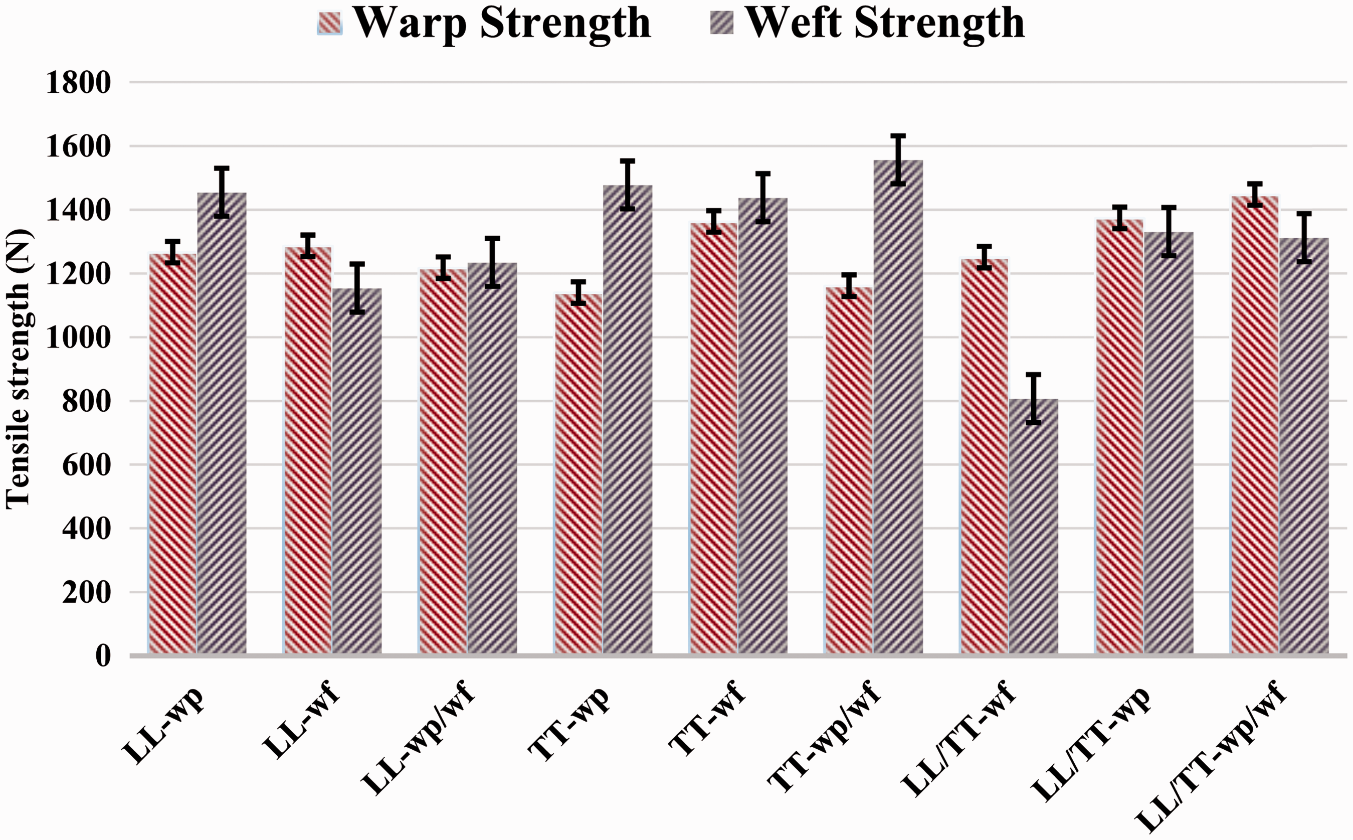
The results of tensile strength for different groups of 3D woven preforms are shown in Figure 3. Since the binder yarns and yarns with higher fold showed lower strength as compared to relaxed/ground yarns present in woven structures, the warp strength in Group A was found to be lower in warp interlock and same was found to be higher in weft interlock structures. This was also because of the bent or fold or crimpness in warp yarns to interlock the weft yarns and extra crimp in binder yarns to interlock the weft layers. Interlocking in warp and weft direction showed average tensile properties of warp and weft in hybrid LL-wp/wf. In Group B, the warp tensile strength of TT samples was lower than the weft tensile strength due to the parallel alignment of double warp/weft yarns in woven structures. It was expected that warp tensile strength in TT-wf should be higher as was seen in Group A, but the reason of the lower tensile strength of warp is the continuous tension on warp yarns during weaving [47].
Tensile strength warp and weft direction.
The design of TT-wp involves more loss strength due to bending from top to bottom and again from bottom to upwards as shown in Figure 1(d). The binder threads exert high compression force to increase inter-yarn friction, hence breakages occur. Best combination in TT was found in a hybrid of Group B. In Group C, LL/TT (wf/wf) hybrid showed the least strength. The warp strength of all samples in Group C was observed to be higher than weft. The higher number of interlacements of yarns in a design reduces strength.
Elongation
As shown in Figure 4, the LL-hybrid (Group A) represents the highest value of elongation%, in the weft direction. The weft yarns were facing more crimp in LL-wp/wf, as these yarns are acting as binding threads for stitching of layers in the weft direction and identical behaviors were observed in warp threads for this design. In Group B, the amount of off-loom relaxation of binding threads was higher as compared to ground yarns. The TT-wf samples have lobular structure developed by the weft-binder. These binders have less ability for crimp buildup. This affects the warps threads to make the lobular structure, which becomes more elongated. When moving towards the hybrid, having to stitch in both warp and weft direction, the elongation in warp was reduced because of the pre-compressed structure. Therefore, the lobular effect will not be produced, and elongations are relatively reduced. In Group C, LL/TT-wf hybrid design has the lowest values overall as well. This design has more incorporated weft threads, while warp threads were almost straight. In hybrid Group C, LL/TT-wp/wf, as mentioned in Figure 3(i), showed the maximum elongation, for both warp and weft ways. It correspondingly had the highest strength in the warp. The reason is more stitching of weft threads in the pattern and formation of float when the weave type is changed from LL to TT.
Elongation% in warp and weft direction.
Tensile modulus
The samples with highest values of elongation resulted in low modulus. Figure 5 shows that more energy is needed to break the fabric either in warp or weft way. Strain values differ in all samples. LL structures (Group A) have the highest strain in binding direction. This can be related to high crimp present in threads this structure. Crimp holds the extra length of yarn in the waveform. When the load increases, first, the yarn tends to become straightened by itself and then breakage occurs. This results in its elongation and strain increases. The higher strain lowers the tensile modulus.
Tensile modulus.
Thickness of fabric
The average areal density of all the samples was 760 GSM. Fabric thickness test was conducted and an average of 10 readings for each sample is plotted in Figure 6.
Thickness measurement of 3D orthogonal woven preforms.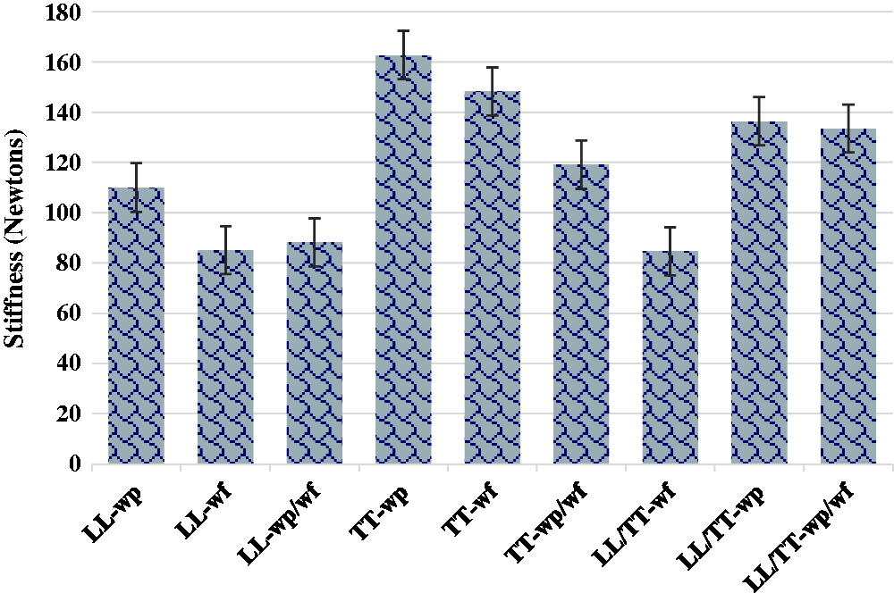
The Group A samples showed the highest thickness as compared to Group B and Group C. Layer to layer (LL) hybrid 3D woven structure showed the highest thickness. This may be caused by the increased float length and the interlocking of yarn for individual layer was at distance. In general, LL 3D woven structure is used for achieving thickness and bulkiness. The Group B fabrics have binder threads which tend to keep the neighboring threads close to each other. This effect causes compactness in threads. The thickness of hybrid structure in Group B was higher as compared to its predecessors. This was the effect of weft yarns displacement into the parallel axis. As on loom, the reed can push the pick into warp sheet. This can place the pick in the position contributing to the thickness. In Group C, the hybrid of LL/TT-wp/wp weave pattern showed maximum thickness in its group. Its value was also higher than the TT structures. LL-wp had higher thickness than TT-wp but their combination resulted in higher thickness than TT-wp and lower thickness than LL-wp. The same trend can be observed in LL-wf and TT-wf combination.
Stiffness test
The graph in Figure 7 shows the stiffness of the fabrics. The stiffness of Group A was lower than that of Group B samples. In Group A, the least stiffness was found in LL-wf design, while the stiffness of LL-wp designs was the highest. In Group B, TT-wp woven structures had the highest stiffness, in fact, highest amongst all nine samples. The Group C has binder set of yarns, which keep the adjacent threads closer and plays role in imparting stiffness. In Group C, the LL-TT-wp and LL-TT-wp-wf/wp-wf samples have almost same values of stiffness due to higher stiffness characteristics of the warp interlock designs. This test was conducted using direct method. The same results were observed by using cantilever method. The higher bending stiffness results in low mouldability or low drapability of the preform. Higher stiffness will affect the bending of the preform in a curved mold when compared to straight moulds. In this study, lower stiffness has been considered for GRA.
Stiffness measurement of 3D orthogonal woven preforms.
AP
Figure 8 shows the AP results of 3D woven structures. The AP of all the samples from either side of the fabric was found to be same. In Group A and Group B, the warp-way fabric samples (LL-wp and TT-wp) showed least AP in their respective groups. The AP trend among the all the groups was found to be increasing. This may be due to the reason that the LL-wp sample was more compact as compared to LL-wp/wf, and so on. The highest AP was observed for LL-hybrid (wp-wf). The AP of TT-wp AP was found to be lowest. This may be due to the binder yarn brings the warp threads closer to each other.
Air permeability of 3D orthogonal woven preforms.
Penetration resistance
Figure 9 shows the results of resistance to penetration. Overall, Group B samples showed higher resistance to penetration followed by hybrids of Group C. Since the penetration resistance is affected by the compactness of structure, Group B have binder set of yarns, which keep the adjacent threads closer. This help in resisting the penetration. Penetration test was conducted on slow speed, 100 mm per minute. The through thickness resistance offered by the preforms is a useful parameter as composite will be robust if the preform is strong.
Penetration resistance of 3D orthogonal woven preforms.
ANOVA
ANOVA results.
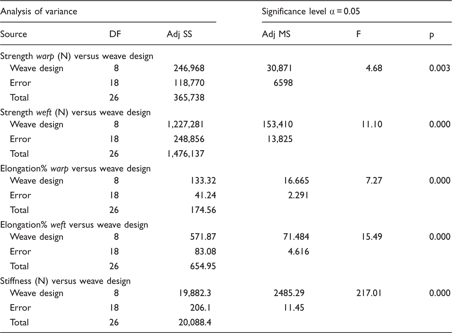
Note: P-values lower than 0.05 indicate strong evidence that weave pattern has a significant effect on mechanical and physical properties of preforms.
Optimization
In this study, the difference of weights (GSM) of fabrics has no substantial difference; hence, this will not be considered for computing GRA.
Factor and response.

The factor, signal to noise ratio (S/N ratio) and normalized S/N ratios values are mentioned in Table 4.
Factor, S/N ratios, and normalized S/N ratios.

The factor, quality loss (Δ) and grey coefficient (GC) values are mentioned in Table 5.
Factors, quality loss (Δ) and grey relational coefficient (GC).

Figure 10 shows the comparative graphs of the grey grade of all samples.
As higher the grey relational grade is considered as a better quality of the product. Figure 10, the value of Grey scale varies from 0 to 1. For better understanding, the reader can consider as percentages.
Grey grade of 3D orthogonal woven preforms.
Parameters attained from grey grade indicate that the hybrids fabrics are better in overall performance. Three weave patterns namely L/T-wp, LL-wp, and LL-wp/wf are close and comparable to each other. These designs have a common pattern of layer-to-layer, either as integral or hybridized. This is due to coherence and integrity of structure which helps in better performance.
Hybrid sample as mentioned in Figure 3(i), LL/TT-wp/wf, showed the highest value for the grey grade. This sample was the combination of all weave designs. Therefore, this is the most suitable and optimum among all woven samples. The pattern has been consistent in its all results. The design included all four basic designs studies in this research. Higher the grey relational grade, better the quality of the product.
Conclusion
The aim of this study was to investigate the mechanical performance of multi-layer orthogonal through thickness and layer-to-layer fabrics, with different interlocking patterns and producing the same designs in weft-way. Nine samples were produced using these weaves. The results are concluded as follows:
The tensile strength of through thickness and layer-to-layer hybrid (LL-TT/wp-wf/wp-wf) interlocked structure was highest in the weft direction. While elongation of the hybrid layer-to-layer (LLwp/wf) structure was highest among all, the self-stitching of warp threads increased the strength in the weft direction. A similar trend was observed for tensile modulus of preforms. The hybrid structures showed an increase the thickness of fabric. It was due to more number of interlocking/intersections in fabric structure. The tightly woven structure produced higher bending stiffness. Hybrids structures showed lower stiffness than TT preforms. A similar trend was observed for the AP; hybrids interlocking resulted in higher AP. The penetration resistance is affected by the compactness of structure and (the Group B have binder set of yarns) keep the adjacent threads close and resulted in higher resistance. ANOVA results depicted that p-values were lower than 0.05, indicates strong evidence that weave pattern has significant effect on mechanical and physical properties of preforms. The optimization performed by GRA showed that highest grey grade was achieved for a fabric having both layers to layer and through thickness structure with warp and weft interlocking. The study concludes that effect of hybridization is advantageous for improving mechanical and physical properties of preforms. It is also concluded that producing a multilayer design in warp direction can be produced in weft direction with almost same mechanical performance and need of dual or multi-weavers beam can be eluded.
In future, development of biodegradable composites will be fabricated and characterized using optimized weaving patterns.
Footnotes
Declaration of conflicting interests
The author(s) declared no potential conflicts of interest with respect to the research, authorship, and/or publication of this article.
Funding
The author(s) disclosed receipt of the following financial support for the research, authorship, and/or publication of this article: The authors are thankful to Higher Education Commission, Pakistan for their funding under Indigenous Fellowship program.