
Abstract
Recently, 3D composites have gained prominence over 2D composites due to their remarkable through-the-thickness reinforcement that enhanced performances of structures subject to multi-directional stress conditions. However, it is at the expense of reduced in-plane properties. 3D composites also increased damage tolerance due to their high impact and delamination resistance properties, which are susceptible in 2D composites. In aeronautics, both are major concerns in primary structures such as lifting and control surfaces due to high vibrational loads from the airflow. Advancements in the aeroelasticity of aircraft structures show an increasing trend in using smart materials with composite structures for improved aeroelastic performance. An example is combining shape memory alloys (SMAs) with composites for improving damping, stiffness, and vibrational characteristics by utilizing stress generation and strain accommodation properties of SMAs in response to temperature and load, respectively. Published works are mostly numerical in nature, and experimental research is noticeably lacking as aeroelasticity is multidisciplinary and involves both structural and aerodynamic methodology. In this work, 3D composites with embedded SMA wires (for improved in-plane properties) are evaluated in terms of flutter performance in wind tunnel flutter testing under low airspeed conditions. Three 3D orthogonal interlock configurations with a different interlocking pattern of yarns with SMA wire were considered. These 3D configurations are layer-to-layer (L2L), through-the-thickness (TT), and a modified interlock (MF) structure that provides the strongest grip to SMA wire than L2L and TT. The effect of SMA positioning, at mid and near to trailing and leading edges of the cantilevered composite plate, on the aeroelastic flutter properties is also investigated. Results showed that activating SMA wires embedded in 3D structures have significantly improved post-flutter properties while there is a decrement in flutter speed and flutter frequency due to increased flexibility of deflected plate in the airflow by SMA-induced stresses. Among 3D structures, L2L with SMA near to trailing edge showed significant improvement in post-flutter properties by decreasing 22.2% in twist limit cycle oscillation (LCO) amplitude while L2L with SMA at mid showed a decrement of 9.5% for bending LCO amplitude. Hence, this work showed that embedding SMA is beneficial for mitigating the post-flutter vibrations but at the consequence of reduced flutter speed and frequency of flexible composite plate.
Keywords
Introduction
Shape memory alloys (SMAs) are responsive to load and temperature. In the martensite phase, SMAs have loosely packed crystalline structures and behave as elastomers that give higher damping properties under applied load. 1 SMAs changed their phase from martensite to austenite at a higher temperature, recovering their residual deformation and generating stresses due to the well-packed crystalline arrangement in the austenite phase. 2 These stresses are responsible for improving the stiffness of the structures. Therefore, the coupling effect of SMAs in response to load and temperature signifies their importance and encourages their embedment in composite structures for improving aeroelastic properties.
Park et al. 3 performed one of the earliest numerical works to modify the aeroelastic flutter characteristics of the composite plate by using SMA. The SMA composite plate was modeled using the first-order shear deformation plate theory (FSDT). The micromechanical approach is used to obtain the constitutive equations of the SMA layer while aerodynamic loads were modeled by the first-order piston theory. It was found that both the natural frequency and the flutter speed of SMA-embedded composite can be modified through the activation of SMA fibers. Another panel flutter analysis was performed by Guo et al. 4 using a nonlinear model of finite elements to investigate the supersonic flutter of composite plates. The quasi-steady first-order piston theory was used to model the aerodynamic pressure over the panel. It was concluded that the introduction of SMA layers into the laminate significantly improved the response of SMA-embedded composite plates. Kuo et al. 5 used a micromechanical approach to obtain effective engineering constant for the SMA layer. The thermal effects were considered to be restricted to SMA fibers. The von-Karman large deformation assumptions and quasi-steady aerodynamic theory were employed. It was shown that a higher volume fraction of SMA fiber was more effective to flutter control.
Cao et al. 6 investigated the effects of shape memory alloy (SMA) wires temperature, pre-strain, and volume fraction on the natural frequency and flutter boundary of a laminated composite panel. The classical plate theory and von-Karman strain displacement relation were used for modeling of composite panel. The third-order piston theory was used for modeling of aerodynamic loads, and the behavior of SMA wire was modeled by the one-dimensional Brinson SMA model. It was concluded that the flutter boundary could be enhanced via heating the SMA wires, raising SMA wires volume fraction, or pre-straining the SMA wires. Recently, Lin et al. 7 investigated the panel flutter to analyze the effects of SMA on the frequency, post-buckling, flutter, and nonlinear aeroelastic. The von-Karman large deformation theory and the third-order nonlinear piston theory were used to model the composite panel. The one-dimensional thermodynamic model was used to simulate the SMA behavior. The third-order piston theory was used to model aerodynamic load, and the noise excitation was simulated by the Gaussian White Noise. It was concluded that the SMA can significantly change the composite panel’s vibration characteristics, which will lead to different flutter behavior of the composite panel. It was noted that the recovery stress generated by SMA reduces the post-buckling amplitude and LCO amplitude of the panel response.
The studies mentioned above are computational studies of the aeroelastic performance of SMA-embedded panel; however, Garafolo and McHugh 8 experimentally investigated the effect of embedded shape memory alloys (SMA) as an active suppression system to mitigate vibrations induced by aeroelastic flutter. A silicone plate with embedded SMA wire was designed. A subsonic wind tunnel was utilized to actuate flutter vibration. It was concluded that SMA can be used in creating variable stiffness components that can be applied to numerous systems that experience fluid-structure interactions. This validation of vibrational suppression of a fluttering plate in the post-critical regime opens the door for future work in active flutter suppression of embedded SMA structures in variable velocities.
The research studies on active tailoring of composites to improve aeroelastic properties are mostly computational studies and related to embedding SMA wires in resin and fibers and there is no experimental research to date that explains the aeroelastic flutter behavior of SMA-embedded 3D woven composites. The aerospace and automotive industries have shown increasing interest in 3D composites due to their excellent damage tolerance and the ability to produce near-net-shape components. 9 2D laminated composites are largely used in many applications, but these structures face delamination under high vibration areas. Also, these structures have poor through-the-thickness properties that limit their applications in high compression areas. 10 Although 2D laminated composites have their importance due to uniform in-plane mechanical and thermo-physical properties but the areas where delamination can occur, 3D woven composites are replacing these structures. Delamination is a big problem in aeronautics due to high vibrations, so 3D structures are preferred in these areas. 3D woven composites were used to replace the expensive metal alloys resistant to high temperature and decrease 30% to 50% of the weight of rocket engines in the 1960s. Avco Company discussed 3D circular woven carbon-carbon fabric composites for airplane brakes in 1972. 3D woven carbon-carbon and carbon-reinforced silicon carbide composite components occupy an important position in aerospace propulsion systems (nozzles) and combustors for high temperatures because of their high strength at elevated temperatures, low specific mass, and low coefficient of thermal expansion. 11
3D woven composites provide a superior damage tolerance that allows a thin, curved blade to be produced, with consequent aerodynamic benefits. 12 “GE90” produced by General Electric (GE) Company, a world-leading producer of jet engines, used 3D aerodynamic modeling to evaluate designs with less number of blades. 13 The GE Company uses 3D woven composites for GE’s next-generation aero-engines airframe and fan casing. Boeing 787 and Airbus A350 have used 3D woven composites for the engine. The CFM International Company developed a fan blade named LEAP-X using 3D woven composites in 2012. The internal structures were the 3D woven composites for fan casing preform, including flanges. 14
The orientation of binding yarns in 3D structures incorporates different properties in structures. The orthogonal interlock structures provide better fiber volume fraction, especially in the thickness direction, 15 higher shear rigidity, 16 resistance to delamination, larger surface damage area, and higher load-carrying or energy absorption capacity, 17 while the angle interlock structures have higher structural stability, fatigue resistance, and folding ability. 18 Low shear rigidity has led to good moldability of the angle interlock fabrics, and applications of such fabrics have been found in making helmet shells and body armor. 19 As the flutter performance of the structures is mainly influenced by bending stiffness parameter “EI” and torsional stiffness parameter “GJ” of the structures,20,21 so the higher bending and shear rigidity of 3D orthogonal structures than 3D angle interlock structures make them the most suitable choice for the current study.
The current research work is the fundamental experimental study of investigating the aeroelastic performance of an SMA-embedded 3D woven cantilevered flexible plate. The flexible composite plate is used for the research to see a considerable effect of SMA on aeroelastic properties with low SMA fraction and also to manifest flutter phenomena at low airspeed. Current work seeks to develop 3D woven smart composite plates having different interlocking patterns of yarns with SMA wire. The aeroelastic flutter properties of these plates with SMA wire at different positions will be assessed. Therefore, this study provides a research opportunity to the experimental aspects.
Materials and methods
Materials
Glass fiber yarn, epoxy resin, and the SMA wire are the materials used for the current research. Glass fiber yarn of type E-glass is used in warp and weft yarns for 3D weaving of glass fabric. E-glass is a calcium alumino-borosilicate glass containing less than 1% alkali. 22 Glass fiber is commonly used for research in the aerospace field. For the current research, the purpose of embedding SMA wire is to improve the stiffness while the high-performance fibers other than glass fiber, such as carbon fiber and aramid fibers, already have higher stiffness. For embedding SMA wires into the composite, the homogeneity between SMA wire and high-performance fibers is very important; otherwise, inhomogeneity cause crack initiation that results in structural failures. 23 Glass fiber shows homogeneity with SMA as its Young’s modulus is near to the Young’s modulus of SMA in the austenite phase. Also, E-glass fiber has low conductivity of electric current that helps in proper activation of SMA wire without leakage of electric current. So, the E-glass fiber is more appropriate for the current research.

Properties of shape memory alloy wire. 30

Force–Temperature Calibration of SMA Wire
The force–temperature calibration of SMA wire is carried out before embedding SMA wire in structures. The term “activation” refers to the complete phase transformation of SMA from martensite to austenite that results in the contraction of the SMA wire. Activation of SMA wire is through joule heating by providing electric current, therefore identifying the temperature limits during activation that provide a consistent contracting force is essential. So, this calibration helps to analyze the effect of temperature variation on the stress generated by the SMA wire. In the experimental setup, one end of the SMA wire is fixed while the other is attached with a force transducer, as shown in Figure 1. The force transducer is used to measure the pull force of the SMA wire at different temperatures. The temperature of the SMA wire is measured using thermocouples and the LabVIEW data acquisition system. With the increment of 0.1 A current applied by the power supply, the temperature and force are measured. The experiment is repeated three times. The experimental results plotted in Figure 2 shows that SMA generated 30.89 N pull force at the activation temperature of 74.59°C. This temperature was achieved by providing 0.83 A electric current and voltage of 7.7 V. (a) Experimental assembly for temperature-force calibration of SMA wire and (b) schematic diagram for temperature-force calibration of SMA wire. SMA temperature–force calibration results.

3D configurations
The current study investigates the aeroelastic flutter performance of three different configurations of 3D orthogonal structures. The 3D orthogonal interlock structures are selected due to superior properties as having better fiber volume fraction, especially in the thickness direction, 15 higher shear rigidity, 16 higher bending rigidity, 31 resistance to delamination, larger surface damage area, and higher load-carrying or energy absorption capacity. 17
Cross-sectional view of 3D structures and their tensile properties.

Manufacturing
Shape memory alloys wire is embedded span-wise in the composite plate that gives a low volume fraction of 0.389% to minimize the effects of SMA activation temperature on the resin material. On the other hand, to achieve higher effects of SMA-induced stresses on aeroelastic properties, the plate is designed as a highly flexible structure with an aspect ratio of 6 and thickness of 0.7 mm. With aspect ratio 6, the composite plate represents a highly flexible structure that will manifest LCO flutter characteristics under low airspeed. Modern aircraft are rapidly being designed to be highly maneuverable by adopting lightweight, flexible, and high-aspect ratio wings in order to achieve high-performance mission objectives. 33 One example is unmanned aerial vehicles (UAVs) that have seen a rapid development due to increased miniaturization of technology, and their multiple usages in both military and civilian fields, thus making the UAV business very profitable. 34 Also, micro-sized air vehicles (MAVs) are based on flexible wings that are capable of aeroelastic tailoring and have favorable characteristics of high stall angles, resulting in a sustained lift at a high angle of attack. 35
For the aspect ratio of 6, the length of the composite plate is kept 300 mm, and the width is kept 50 mm. An additional 50 mm of sample is needed to clamp samples for modal and aeroelastic analysis. So, the dimensions of the samples are 350 × 50 × 0.70 mm3 for the wind tunnel test to determine the aeroelastic performance of SMA-embedded 3D woven composites.
For wind tunnel test to analyze aeroelastic flutter behavior, it is essential to keep both ends of the SMA wire at the clamping area so that connecting wires do not affect the aeroelastic performance of the cantilevered composite plate. So, during the 3D weaving process, SMA wires are embedded in a U-shape pattern that travels from root-end to near the tip-end and goes back to the same root-end. The radius of U-folding at the tip-end is small to ensure minimal lateral contraction when SMA is activated. In this way, both ends of SMA wires are at one side of the structure, as shown in Figure 3. The cross-sectional views of 3D structures with two SMA wire ends are shown in Figure 4. Embedding SMA wires during 3D weaving. Cross-sectional views of 3D structures with two embedded SMA wires.

The aeroelastic flutter properties of composite plates are evaluated with respect to different positions of SMA wires in the composite plate. The SMA wires are embedded at mid, near the trailing edge, and near the leading edge. The position of SMA imparts different aeroelastic behavior due to its effect on bending and torsional stiffness. The dimensions of the composite plate with different positions of SMA wires are shown in Figure 5. The position of SMA wire in plate-like wing (span-wise): (a) at mid; (b) near to trailing edge; and (c) near to leading edge.
Experimental setup for wind tunnel flutter testing
Aeroelastic flutter analysis is done by performing the flutter test in the subsonic wind tunnel in accordance to well-established procedures employed by Hollowell and Dugundji, 36 Majid and Basri, 37 Hussein et al., 38 and Garafolo and McHugh, 8 to analyze the aeroelastic properties of a cantilever plate in the subsonic wind tunnel. The composite plate of each 3D configuration is cantilevered by mounting at the base of the wind tunnel, and airspeed is increased until the structure exhibits violent vibration motions. A triaxial strain gauge is attached to the sample. Triaxial strain gauge contains three strain gauges: one is parallel to the span for measuring bending strain, the second one is at 45° for measuring torsional strain, and the third one is perpendicular to the span measuring perpendicular strain. The time history of bending and torsional strains is monitored, and the airspeed is noted when the bending and torsional strains coupled with each other, that is, the frequencies of bending and torsional strains merged each other at a point. The airspeed at this moment is flutter speed, and the phenomenon is flutter onset. After flutter onset, the amplitude of oscillations is limited to a constant. This phenomenon is well established, particularly to cantilevered plate structures and known as limit cycle oscillations (LCOs).33,35 From the limit cycles, the flutter frequency can be obtained. The procedure is performed for inactive SMA wire as well as for activated SMA wire to evaluate the effect of SMA on aeroelastic flutter properties. The various components involved in the wind tunnel testing to evaluate the flutter properties are described in the following subsections.
Subsonic wind tunnel
The present flutter test is performed in a (1 × 1) m2 subsonic wind tunnel. The wind tunnel is an open circuit, low turbulence continuous flow tunnel. It provides air velocities up to 40 m/s, equal to the Mach number, M ∼ 0.12, and has a variable speed driving system. The sample is mounted at the base of the wind tunnel, as shown in Figure 6. With the base mount, the gravitational effects are eliminated. 3D woven composite sample mounted at the base of the wind tunnel at 0° angle of attack: (a) front view and (b) side view.
Test sample preparation
For measuring bending and torsional strains, a triaxial strain gauge of type Kyowa “KFRP-5-120-D22-9L3M2S” is pasted on the sample using the strain gauge cement of type “CC-3A” as shown in Figure 7. The strain gauge oriented along with the span direction measures the bending strain, and the strain gauge at 45° off the span direction measures the torsional strain. The strain gauges are bonded near to the root of the composite plate, where the bending and torsional strains are high. Once bonding is cured, the masking tape is applied over the strain gauge and its connection wires to avoid any vigorous movement during testing and ensure the strain gauge readings are stable. After bonding the strain gauge, its resistance is measured to ensure its working. The acceptable range of strain gauge resistance is 120–122 Ω. Test sample with pasted triaxial strain gauge.
Data acquisition system
The data acquisition system is responsible for acquiring bending and torsional strains from the strain gauge. The system is capable of online monitoring as well as recording the strain values at high rates. The complete data acquisition setup is shown in Figure 8. The strain gauge is connected to the data acquisition system (National Instruments, NI cDAQ-9174) that is attached to a computer system having LabVIEW software (National Instruments LabVIEW 2012). Direct strain readings are displayed on the front panel of LabVIEW, and it also saves the strain data. This strain data is used to analyze the aeroelastic behavior of composites in which the flutter onset is determined when the amplitudes of oscillations start to diverge, and LCO amplitudes provide the calculation for the flutter frequency. Data acquisition setup for strain measurement.
Wind tunnel airspeed calibration
The wind tunnel airspeed calibration involved calibrating the rpm of the variable speed motor of the wind tunnel to the airspeed in the test section. The calibration constant will indicate the airspeed in the wind tunnel corresponding to the change in the rpm. The airspeed calibration is conducted before running the flutter test. The test is performed by measuring the dynamic pressure in the wind tunnel while varying the motor speed. A digital manometer with a pitot tube is used to measure the dynamic pressure of the air and convert it into airspeed.
With an empty test section, the variable motor speed is increased from zero, and the corresponding value of airspeed is noted. The whole process is repeated three times, and the average value of airspeed is taken. The averaged airspeed is plotted against the rpm of the motor, as shown in Figure 9. The graph shows an excellent correlation between the rpm of the motor and airspeed as the r-square value is 0.9988. The slope of the line determines the change in airspeed with respect to rpm. By increasing 1 rpm of the motor, the airspeed increases 0.7862 times. This shows that during aeroelastic flutter testing, increment in airspeed is controlled properly. Wind tunnel airspeed calibration w.r.t motor’s rpm.
The most important is the careful study of aerodynamic phenomena as the structures are affected by the variation of Reynolds number. Reynolds Number (Re) determines the nature of the flow, that is, laminar or turbulent is, and it is calculated by “
Wind tunnel flutter test procedure
The sample was base-mounted inside the wind tunnel and aligned at 0° angle of attack with zero swept, as shown in Figure 6. The triaxial strain gauge bonded at the sample surface was connected with a DAQ system that was further connected to LabVIEW software. The SMA wire of the sample was connected with a power supply for activating the SMA wire by providing electric current to the SMA wire. An Infra-red thermal camera “FLIR E60 (IR resolution 320 × 240)” was used to monitor and record the SMA wires’ temperature. The laser beam of the thermal camera was targeted at a fixed point on the SMA wire for monitoring the temperature of SMA wires inside structures during the test, as shown in Figure 10. Thermal camera measuring the temperature of shape memory alloy wire.
The whole flutter test setup is shown in Figure 11. First of all, the testing is conducted for layer-to-layer without SMA wire. The airspeed of the wind tunnel was increased gradually by increasing motor rpm from zero until the plate was observed to exhibit violent vibration motions. The time history plot of the strain was achieved from LabVIEW and plotted in Excel. The flutter was defined whereby the amplitude of oscillations of the sample increased rapidly. The tunnel airspeed at that particular time was noted, and this speed was the flutter speed. To achieve the flutter frequency and LCO amplitude of bending strain and torsional strain, the time history plot of bending and twist at flutter onset was zoomed-in, and the amplitude of the oscillations was measured at LCO. Wind tunnel flutter test setup.
Now, the same process was performed for L2L with SMA at mid, and the flutter speed was noted. For activating SMA, the electric current was provided to the SMA wire using the power supply, and the SMA activation temperature was observed and recorded by the thermal camera. With increasing airspeed, the rate of temperature drop of SMA wire increased due to the cooling effect of displaced air from the surface of the plate. Simultaneously, the temperature of SMA was maintained at activation temperature by increasing electric current with respect to airspeed. Increasing airspeed and temperature was continued until flutter speed, and the SMA wire was kept activated during the test.
Similarly, the procedure of wind tunnel flutter testing was repeated for other configurations encompassing the L2L with inactive and activated SMA near to trailing and leading edges, TT without SMA wire, TT with inactive and activated SMA at mid and near to trailing and leading edges, MF without SMA wire, and MF with inactive and activated SMA at mid and near to trailing and leading edges. The aeroelastic behavior of each 3D configuration without SMA and with inactive and activated SMA was analyzed from the time history plot of strain for bending and twist. The flutter onset for inactive and activated SMA was compared. Also, the amplitude of bending and twist LCO for both active and inactive SMA was compared.
The effect of embedding SMA wire in 3D composite plates was analyzed by comparing the flutter speed, flutter frequency, and LCO amplitude of 3D structures without SMA and inactive and activated SMA wire at different positions. Also, the effect of 3D configurations on aeroelastic performance was analyzed.
Results and discussion
The aeroelastic results are first presented as time history plots of both bending and torsional strains that will overview the overall aeroelastic behavior for all the 3D configurations across different combinations of conditions. The airspeed inside the wind tunnel is also indicated with respect to the time, and the flutter speed is highlighted. The aeroelastic behavior of each 3D configuration is discussed in the following subsections.
Aeroelastic behavior of 3D woven layer-to-layer interlock composite plates
When the cantilevered plate is subjected to airflow, the pressure distribution along the span of the cantilevered plate results in the deflection of the plate, while the stiffness of the plate provides the restoring force that deflects the plate in the opposite direction that further changes the pressure distribution. This continuous aeroelastic interaction resulted in a static deflection as well as oscillatory vibration of the plate. Hence, the cantilevered plate undergoes bending, twist, and oscillation when subjected to airflow.
For L2L without SMA wire, when the airflow speed is increased starting from zero, there is a sharp increase in the static deflection of the plate, and then, it steadily increases until it reaches the flutter speed, as shown in Figure 12(a). At flutter speed, the plate was observed to exhibit violent harmonic vibration motions, and at this point, the frequencies of bending and twisting modes merged to produce limit cycle flutter oscillations. Aeroelastic behavior of L2L (a) without SMA; (b) inactive SMA at mid; (c) activated SMA at mid; (d) inactive SMA near to trailing edge; (e) activated SMA near to trailing edge; (f) inactive SMA near to leading edge; and (g) activated SMA near to leading edge. Note: SMA, shape memory alloy.
The same behavior is seen for the composite plate with inactive SMA wire at mid as it contributes evenly to improve the stiffness of the plate, as shown in Figure 12(b). While for the inactive SMA embedded eccentrically, the static deflection steadily increases without any sharp increment, as shown in Figures 12(d) and (f). The only difference at this point is the flutter parameters which are improved due to the increased bending stiffness of the composite plate via the SMA wire reinforcement.
On the contrary, upon activation, change from martensite to austenite phase resulted in closely packed structures that not only contributed to in-plane stiffness, but also induces a contracting force along the SMA wire. This force acts upon the composite plate and depending on the shape of the deflected plate under airflow, the loading direction of the SMA force will also dynamically changes as the plate undergoes oscillating motions. This observation will be further elaborated in the following results pertaining for configurations with activated SMA.
When SMA is activated, it remarkably decreases the magnitudes of static deflections as well as there is a reduction in the amplitude of twist oscillation due to the stiffness induced by the SMA wire. For activated SMA at mid, initially, the twist decreases while bending has a sharp increment. Then, twist increases sharply while bending decreases due to SMA-induced stress. Then, both increase steadily to the flutter speed, as shown in Figure 12(c). The increasing trend of bending and twist with activated SMA wire is not as smooth as for inactive SMA due to the change in temperature of SMA wire that is manually controlled. As the airspeed of the wind tunnel increases, the temperature of the SMA wire decreases due to the cooling effect of the air. The temperature is maintained at a mean value of 75°C with a standard deviation of 2.59°C to keep the SMA wire fully activated by regulating the electric current provided to the SMA wire. For activated SMA wire near to trailing edge, the magnitude of the twist is remarkably decreased also the magnitude of the bending decreases as shown in Figure 12(e), and also for the activated SMA near to the leading edge, the bending and twist show similar behavior. Initially, the magnitude of both decreases, then there is a sharp increase in the magnitude and then again decreases. Finally, it increases to flutter speed, as shown in Figure 12(g).
The flutter speeds of the inactive SMA-embedded composite plates are relatively higher than the composite plate without SMA wire as the addition of SMA wire increases the plate’s stiffness, resulting in higher flutter speeds. But the important finding is that when activating SMA wire, there is a significant decrease in flutter speed, that is, 9.6% for SMA at mid, 11.15% for SMA near to the trailing edge, and 10.76% for SMA near to the leading edge. The decrement of flutter speed when SMA wire is activated results in the early occurrence of flutter phenomenon compared to inactive SMA wire.
For a rigid plate that remains at a straight position without deflection during aerodynamic loading, the SMA wire upon activation increases the bending stiffness, EI, of the plate due to SMA-induced stresses that ultimately results in improvement of the flutter properties as reported by Cao et al.,
6
Barzegari et al.,
40
Donadon and De Faria,
41
and Samadpour et al.
42
But for the current study, the composite plate is flexible and is in the deflected position due to aerodynamic loading. The contraction of the activated SMA wire will not be parallel to the x-axis of the plate, but instead, it will be acting tangent to the slope of the deflection curve due to the curvature of the elastic curve as shown in Figure 13(c). This creates components of SMA-induced stresses in the x-axis and y-axis with magnitudes that vary with the angle of the tangential slope along the cantilevered plate’s span. These components of SMA-induced stresses will further increase the bending moment of the plate along with airflow that causes to increase the flexibility of the plate, thus inducing flutter to occur at a lower speed. Therefore, when SMA-embedded structure bends, the SMA-induced stresses are not only contributing to increasing the stiffness of the structure but also have the tendency to increase the bending moment along with air pressure. To further strengthen the hypothesis, a simple two-dimensional cantilevered beam analogy can be used to describe this effect. (a) SMA-induced in-plane stresses in the composite plate without airflow; (b) uniform varying load applied by wind tunnel airflow to the composite plate; and (c) SMA-induced stresses in the composite plate under wind tunnel airflow. Note: SMA, shape memory alloy.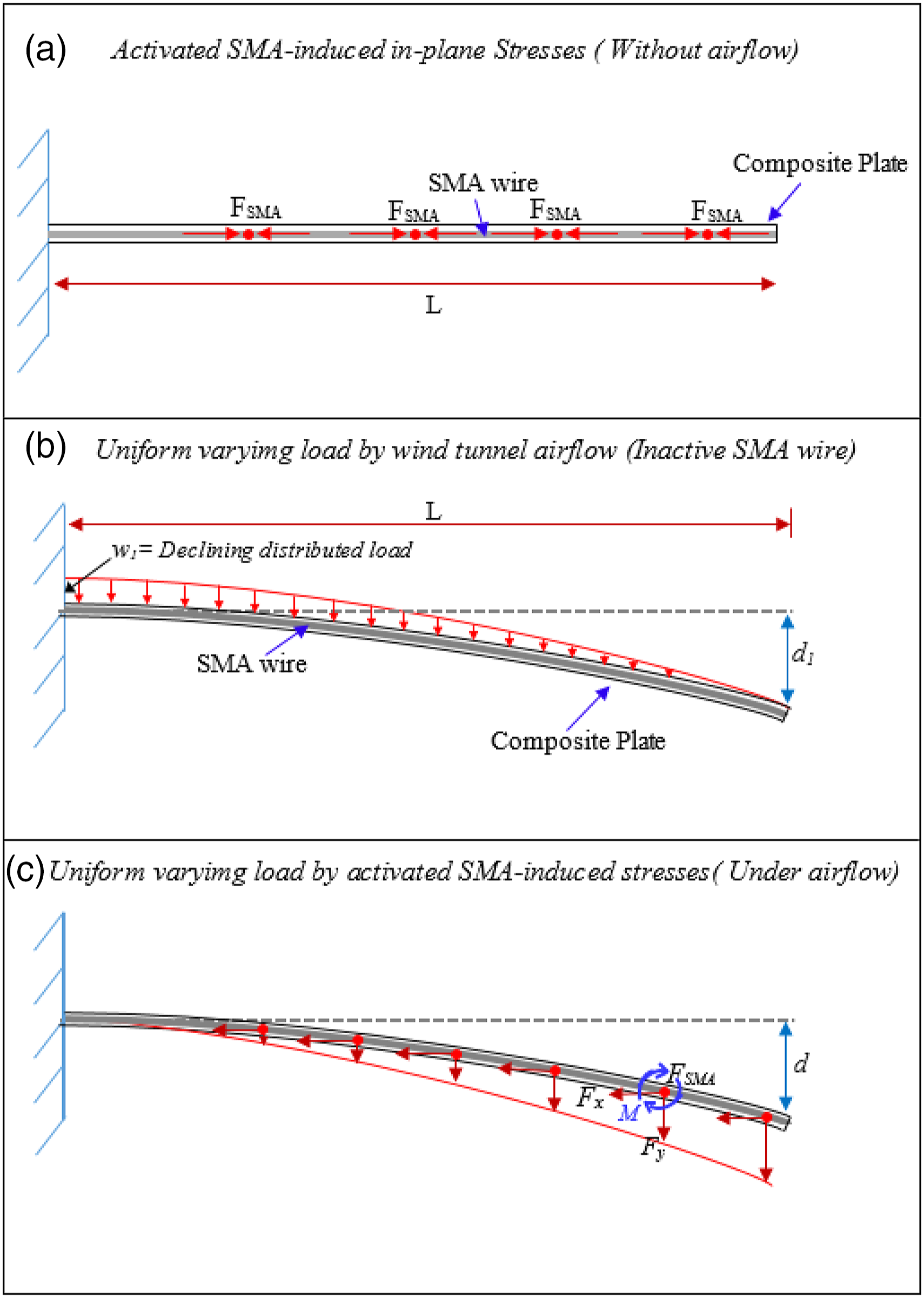
The elastic behavior of the composite plate is explained by assuming that the plate-like wing is behaving like a beam (ratio of span to width is large) with isotropic properties. The cantilevered composite plate with embedded SMA wire is shown in Figure 13. When there is no airflow in the wind tunnel, the induced SMA stresses are shown in Figure 13(a). The plate is at a straight position, and the induced stresses contribute to increasing the stiffness of the plate.
In subsonic airflow, pressure distribution along the span of the cantilevered plate resulted in the deflection of the plate that changes the aerodynamic force and leads to change in the deflection, and this is aerodynamic and elastic interactions defined as aeroelasticity. Initially, the plate restores its position due to its elastic properties, but it deflects significantly when the airspeed is further increased. A snapshot of the downward deflection of the plate without activating the SMA wire is shown in Figure 13(b). When the SMA wire is activated, and the plate is deflected in the airflow, due to the curvature of the elastic curve, the contraction of the SMA wire will not be parallel to the x-axis of the plate; instead, it will be acting tangent to the slope of the deflection curve. On an arbitrary point along with the plate, the SMA-induced forces are represented in “x” and “y” components, as shown in Figure 13(c).
The aerodynamic loading mainly depends on the pressure of airflow and is mainly responsible for the bending of the plate.7, 39,40 The weight of the plate and other factors are neglected as these are the same for inactive and activated SMA wires. For an instantaneous moment, let us assume the aerodynamic load is distributed along with the plate (as shown in Figure 13(b)), and SMA-induced stresses resulted in a uniformly distributed load along with the plate (as shown in Figure 13(c)); then, the bending moment and deflection of the plate is achieved by solving the equation of the elastic curve of a cantilevered beam. The resultant moment and deflection of the plate will be the combined effect of the aerodynamic load and SMA-induced stresses.
The percentage increment in bending moments of 3D L2L, TT, and MF by activated SMA wire at mid and trailing and leading edges, simplified as a cantilevered beam.

Note: SMA, shape memory alloy.
From Table 4, it is clear that the bending moments of activated SMA wires are significantly higher than inactive SMA wires. L2L and TT have higher percentage increments than MF. MF is a rigid structure and has a strong interlocking of yarns with SMA, so it provides less freedom to SMA to increase bending moment; hence, the percentage reduction of flutter speed is lower for MF than L2L and TT.2,41 The percentage increment in bending moments is relatively lower for the plates with eccentrically embedded SMA wires than SMA wire at mid. When eccentrically embedded SMA wire is activated, it creates an unbalance torque due to more stiffness at one side of the plate that promotes the merging of the frequencies at lower speeds with lower bending moments, while the plate with SMA at mid has an even contribution of SMA-induced stresses and bends more before the occurrence of the flutter phenomenon. Due to the same reason, the percentage decrement of flutter speed is higher in the plates with eccentrically embedded SMA wire compared to SMA wire at mid.
After flutter onset, the amplitude of oscillations of the composite plate became limited to a constant due to structural nonlinearities. This phenomenon is known as limit cycle oscillations (LCOs) and also reported by Cao et al.,
6
Lin et al.,
7
Majid and Basri,
37
and Barzegari et al.
40
To analyze the LCO behavior of bending and twist, the flutter onset area of L2L without and with inactive and activated SMA at mid and near to trailing and leading edges is zoomed-in as shown in Figure 14. The magnitudes of LCO of bending and twist decrease when the SMA wire is activated, which shows that the induced stiffness of the SMA wire reduces the amplitude of the oscillations after flutter. The reduction of LCO magnitudes by activation of SMA wire is also reported by Cao et al.,
6
Lin et al.,
7
and Barzegari et al.
40
The reduction of LCO magnitudes by activation of SMA wire is beneficial for aircraft structures as vibration caused by LCOs causes fatigue that poses significant problems and reduces the structure’s useful life.
43
Flutter onset of L2L (a) without SMA; (b) inactive SMA at mid; (c) activated SMA at mid; (d) inactive SMA near to trailing edge; (e) activated SMA near to trailing edge; (f) inactive SMA near to leading edge; and (g) activated SMA near to leading edge.
The bending LCO magnitude has a higher percentage decrement for the composite plate with SMA at mid as it evenly increases the bending stiffness of the whole plate. In comparison, the twist LCO magnitude has a higher decrement than bending when SMA at trailing and leading edges. The SMA near to trailing or leading edges stiffens one side of the plate, reducing the magnitude of the twist oscillations. So, the activation of the SMA results in the reduction of LCO magnitudes, and the mitigation of the flutter vibrations certainly is desired.
The flutter frequency is also an essential aeroelastic property that plays a key role in occurrence of the flutter phenomenon. An increase in bending stiffness results in higher flutter frequency as the bending and torsion modes merge at higher frequencies. 44 It is calculated by counting the number of cycles for 1 s of limit cycle oscillations (LCOs). It increases by the addition of SMA wire as the inactive SMA-embedded composite plates have relatively higher flutter frequencies than the plates without SMA wire. Due to the higher stiffness of the plates with the addition of SMA wire, the bending mode and torsional mode frequencies are raised, and the merging of bending and torsion modes occurs at higher frequencies that results in higher flutter frequencies. 44
Flutter properties of 3D woven layer-to-layer interlock composite plates.

Aeroelastic behavior of 3D woven through-the-thickness composite plates
The results of the aeroelastic flutter test are analyzed for 3D woven through-the-thickness interlock composite plates without SMA wire, inactive and activated SMA wire at mid and near to trailing and leading edges. For TT without SMA wire, when the airflow speed is increased starting from zero, the static deflection steadily increases until the flutter speed, as shown in Figure 15(a). The same behavior is seen for the composite plate with inactive SMA wire at mid and near to trailing edge and leading edge as shown in Figures 15(b), (d), and (f). Aeroelastic behavior of TT (a) without SMA; (b) inactive SMA at mid; (c) activated SMA at mid; (d) inactive SMA near to trailing edge; (e) activated SMA near to trailing edge; (f) inactive SMA near to leading edge; and (g) activated SMA near to leading edge. Note: SMA, shape memory alloy.
When SMA is activated, it decreases the magnitudes of static deflections due to the stiffness induced by the SMA wire. For activated SMA at mid and near to trailing and leading edges, bending is decreased while the twist did not much affect before flutter as shown in Figures 15(c), (e), and (g). The oscillation amplitude of twist reduced for the composite plate with SMA near to leading edge, while for the SMA at the mid and near to trailing edge, the oscillations are not significantly affected.
Similar to L2L, the addition of inactive SMA wire results in improvement of flutter speed. When the SMA wire is activated, there is a significant decrease in flutter speed, that is, 7% for SMA at mid, 9.84% for SMA near to trailing edge, and 8.9% for SMA near to the leading edge. The percentage decrease of flutter speed is higher in the plates with eccentrically embedded SMA wire compared to SMA wire at mid. Due to the eccentricity, the SMA wire creates an unbalanced torque when activated due to more stiffness at one side of the plate that promotes the merging of the frequencies at lower speeds. Also, due to the same reason, the maximum static deflection of the plate before flutter is relatively lower for the plates with eccentrically embedded SMA wires than SMA wire at mid.
To analyze the post-flutter behavior of TT, the flutter onset area of TT is zoomed-in, as shown in Figure 16. The magnitudes of LCO of bending and twist have decreased when SMA wire is activated, which showed that the induced stiffness of SMA wire had reduced the amplitude of the oscillations after flutter. The bending LCO magnitude has a higher percentage decrement for the composite plate with SMA at mid as it has evenly increased the bending stiffness of the whole plate, while the twist LCO magnitude has a higher decrement than bending when SMA wire is near to trailing and leading edges. The SMA wire near to trailing or leading edges stiffens one side of the plate, reducing the magnitude of the twist oscillations. So, the activation of the SMA results in the reduction of LCO magnitudes. Flutter onset of TT (a) without SMA; (b) inactive SMA at mid; (c) activated SMA at mid; (d) inactive SMA near to trailing edge; (e) activated SMA near to trailing edge; (f) inactive SMA near to leading edge; and (g) activated SMA near to leading edge. Note: SMA, shape memory alloy.
Flutter properties of 3D woven through-the-thickness interlock composite plates.

Aeroelastic behavior of 3D woven modified interlock composite plates
The results of the aeroelastic flutter test are analyzed for 3D woven modified interlock composite plates without SMA wire, inactive and activated SMA wire at mid and near to trailing and leading edges. For MF without SMA wire, when the airflow speed is increased starting from zero, the static deflection steadily increases until the flutter speed, as shown in Figure 17(a). The same behavior is seen for the composite plate with inactive SMA wire at mid and near to trailing and leading edges as shown in Figures 17(b), (d), and (f). Aeroelastic behavior of MF (a) without SMA; (b) inactive SMA at mid; (c) activated SMA at mid; (d) inactive SMA near to trailing edge; (e) activated SMA near to trailing edge; (f) inactive SMA near to leading edge; and (g) activated SMA near to leading edge. Note: SMA, shape memory alloy.
When SMA wire is activated, it significantly decreases the magnitudes of static deflections due to the stiffness induced by the SMA wire. For activated SMA at mid and near to trailing and leading edges, the magnitudes of bending and twist decrease as shown in Figures 17(c), (e), and (g). The oscillation amplitude of twist reduced for the composite plate with SMA at mid while for the SMA near to trailing and leading edges, the oscillations are not significantly affected.
Similar to L2L and TT, the addition of inactive SMA wire improves flutter speed. When the SMA wire is activated, there is a significant decrease in flutter speed, that is, 13.8% for SMA at mid, 16.4% for SMA near to trailing edge, and 15.8% for SMA near to leading edge. The percentage decrement of flutter speed is higher in the plates with eccentrically embedded SMA wire due to an unbalance torque created by activated SMA wire that promotes the merging of the frequencies at lower speeds. Also, due to the same reason, the maximum static deflection of the plate before flutter is relatively lower for the plates with eccentrically embedded SMA wire.
To analyze the LCO behavior of bending and twist, the flutter onset area of MF without and with inactive and activated SMA at mid and near to trailing and leading edges is zoomed-in as shown in Figure 18. The magnitudes of LCO of bending and twist decrease when the SMA wire is activated, which shows that the induced stiffness of the SMA wire reduces the amplitude of the oscillations after flutter. Similar to L2L and TT, the bending LCO magnitude has a higher percentage decrement for the composite plate with SMA at mid, while the twist LCO magnitude has a higher decrement when SMA wires are at trailing and leading edges. Flutter onset of MF (a) without SMA; (b) inactive SMA at mid; (c) activated SMA at mid; (d) inactive SMA near to trailing edge; (e) activated SMA near to trailing edge; (f) inactive SMA near to leading edge; and (g) activated SMA near to leading edge. Note: SMA, shape memory alloy.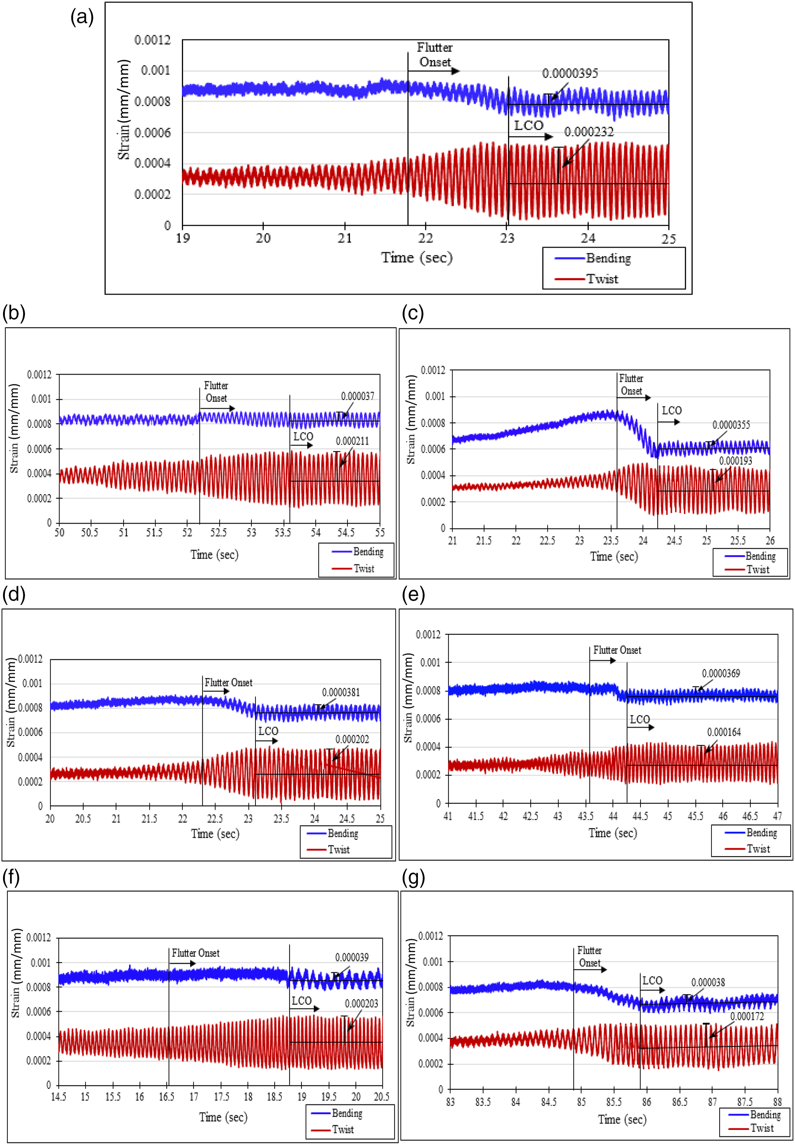
Flutter properties of 3D woven modified interlock composite plates.

Effect of SMA positioning and 3D configurations on aeroelastic performance of the composite plate
The position of the SMA wire is an important factor that affects the aeroelastic properties. The flutter speeds and flutter frequencies are decreased by activating the SMA wire due to the contribution of SMA-induced stresses for increasing bending moment. The comparisons of reduction in flutter speeds and flutter frequencies of 3D composite plates with SMA wire at mid and near to trailing and leading edges are shown in Figure 19. The percentage decrement of flutter speed and flutter frequency is higher for the composite plates with SMA wire near to trailing and leading edges than SMA wire at mid. The eccentricity of the SMA wire is responsible for unbalanced torque when the SMA wire is activated that promotes twisting, and hence flutter speed decreases. Due to promoted twisting of the composite plate, the merging of bending and torsional modes occurs at lower frequencies resulting in lower flutter frequencies for SMA near to trailing and leading edges. (a) Percentage reduction in flutter speed by activating SMA wire and (b) percentage reduction in flutter frequency by activating SMA wire.
The bending and twist LCO amplitudes are reduced when the SMA wire is activated due to SMA-induced stresses. The comparison of percentage reduction in LCO amplitude of 3D composite plates with SMA wire at mid and near to trailing and leading edges is shown in Figure 20. The reduction of bending LCO amplitudes of the composite plate with SMA wire at mid is higher than the composite plates with SMA near to trailing and leading edges due to even increment of the bending stiffness for both sides of the plate that limits the vibrations of the plate. However, the reduction of torsional strain LCO amplitudes of the composite plate with SMA wire near to trailing and leading edges is higher than the composite plates with SMA at mid due to increased stiffness of trailing and leading edges that limits the torsional vibrations of the plate. Percentage reduction in LCO amplitude of (a) bending and (b) twist. Note: LCO, limit cycle oscillation.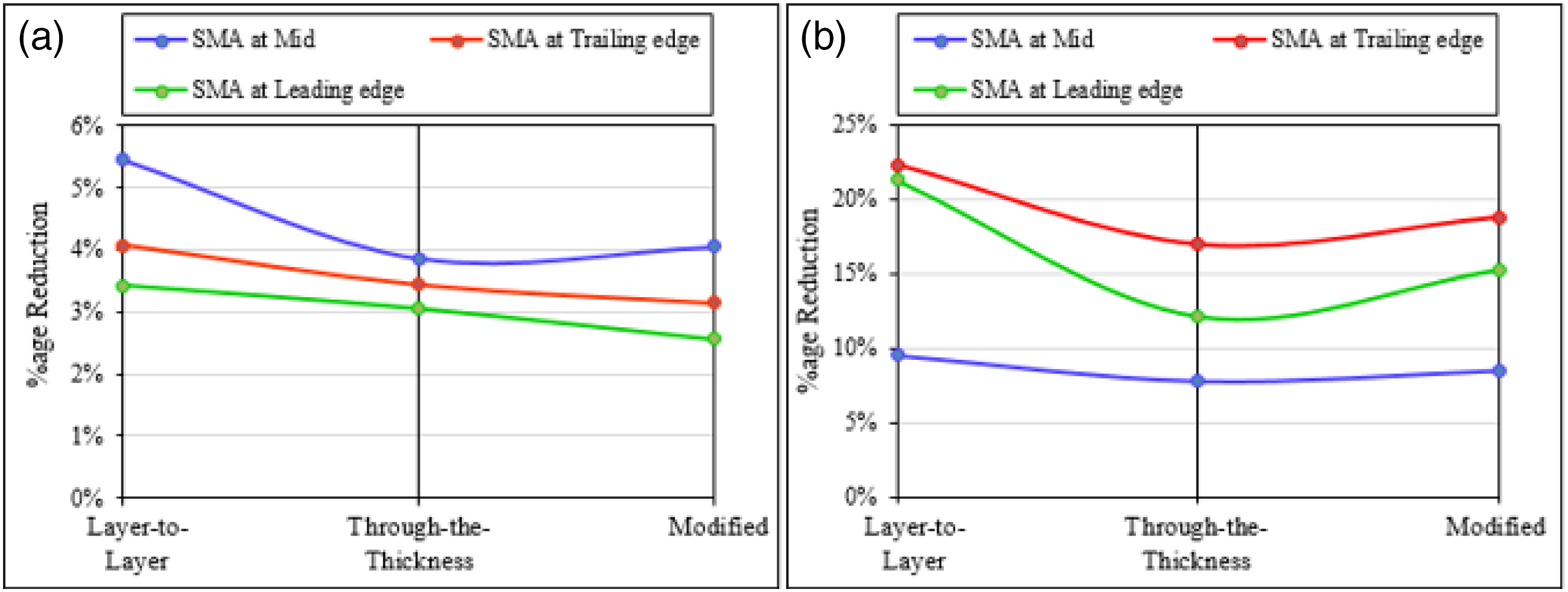
To conclude, the SMA wire at mid position contributes evenly to both sides of the composite plate, so the composite plate with SMA wire at mid has higher aeroelastic properties than SMA near to trailing and leading edges. The configuration of 3D structures also has a significant effect on the aeroelastic properties of the composite plate. The SMA wire embedded in 3D structures behaves differently for 3D configuration due to the interlocking of SMA wire with binding yarns. From Figure 19, MF has the lowest percentage reduction in flutter speed and flutter frequency when SMA wire is activated, while the L2L has the highest percentage reduction. From the results mentioned in Table 3, it was proven that the contribution of SMA is higher for L2L in improving tensile properties; similarly, the contribution of SMA promotes a higher bending moment for L2L that results in the higher reduction of flutter speeds and flutter frequencies. On the other hand, MF is a rigid structure and restricts SMA wire due to the strong interlocking of yarns to SMA, so its contribution is lower in promoting bending moment; hence, the reduction in flutter speed and flutter frequencies is lower for MF.
3D configurations also affect the bending and twist LCO amplitudes. From Figure 20, L2L has the highest reduction percentage in bending and twist LCO amplitudes while the MF has the lowest percentage reduction. This is also due to the higher contribution of SMA wire for L2L and the lowest for MF, which ultimately reduced the oscillation due to induced stresses.
Conclusion
The SMA wires are successfully embedded in three different configurations of 3D woven flexible composite plates, and their aeroelastic flutter properties are investigated. The conclusions are summarized as following: (a) Shape memory alloy wires embedded in 3D composite structures significantly affect the aeroelastic performance of the structures by increasing the resultant bending moment of the cantilevered plate, leading to lower flutter speed and frequency while the post-flutter properties are improved through reduced bending and twist LCO amplitudes. (b) The position of the SMA wire has a significant effect on the aeroelastic properties as the off-centered chordwise position of the SMA wire induced twist and resulted in early flutter occurrence due to unbalanced torque compared to mid-chord positioning. Also, reduction in twist LCO amplitudes is higher for off-centered SMA. (c) The 3D configurations also affect the aeroelastic properties as the compact 3D modified interlock structure shows better aeroelastic performance than other 3D structures, while the L2L has higher post-flutter properties when SMA wire is activated due to more freedom to SMA wire for stress generation. L2L with SMA near to trailing edge showed a significant decrement of 22.2% in twist LCO amplitude, while L2L with SMA at mid showed a decrement of 9.5% for bending LCO amplitude.
Hence, this work showed that embedding SMA is beneficial for mitigating the post-flutter vibrations but at the consequence of reduced flutter speed and frequency.
Footnotes
Declaration of conflicting interests
The author(s) declared no potential conflicts of interest with respect to the research, authorship, and/or publication of this article.
Funding
The author(s) disclosed receipt of the following financial support for the research, authorship, and/or publication of this article: The authors would like to acknowledge the financial support from the Ministry of Higher Education with grant no. FRGS/1/2019/STG07/UPM/02/10 and VOT No. 5540209.