
Abstract
The focus of this work is to find the impact loading properties of three types of three-dimensional woven kevlar fabric structures before and after impregnation with epoxy resin. The analysis has been done at different impact times and different magnitude of forces. Total deformation, equivalent strain and equivalent stress created on these fabrics have been noted. First a model of three-dimensional woven fabric composite is generated using SolidWorks 2011. The model is constructed in such a way that it can be readily integrated into commercial finite element programs like ANSYS. Then impact resistance of this model is simulated and studied with impacts at different initial velocities. By incorporating the interface of fabric and matrix, the impact resistance is predicted. The simulated results are validated with experimental data. A compatible resin/matrix system has to be selected along with the fabric in order to develop sufficient resistance to impact. The three-dimensional woven kevlar-epoxy composites prove to be effectively resistant to impact due to interface of fiber and matrix system.
Keywords
Introduction
The aim of this work is to find the impact loading properties of three types of three-dimensional (3D) woven aramid fabric structures before and after reinforcement with epoxy resin and compare the results. An engineered 3D fabric composite is made from two or more components. One component is mostly a strong fiber-like glass fiber, kevlar or carbon fiber that gives composite material the required mechanical property and the other component (called matrix) is mostly a resin, such as epoxy or polyester, that binds the material together [1–3].
Many light-weight ballistic-protection armor systems are currently being made of the so-called “ballistic-grade” or “armor-grade” composites. The armor-grade composites are increasingly being used for ballistic protection in light-weight armored vehicles, helicopters, patrol boats, transportable shelters (e.g. command shelters) and for bullet-protective armor systems. These composites are generally constructed using high-modulus/high-strength polymeric fibers such as aramid (e.g. Kevlar®, Twaron® etc.) or oriented polyethylene fibers (e.g. Spectra®, Dyneema® etc.) or glass fibers (e.g. E-Glass etc.) with an outstanding impact resistance [4]. The fibers, in the form of either woven fabrics or in the form of 0°/90° cross-plied continuous filaments, are embedded in the resin/polymer matrix. To attain maximum utilization of the inherently high transverse-impact resistance of the fibers, the polymer-matrix content does not typically exceed 20 vol.% [5,6]. As a result of the very low resin content, these composites remain flexible to relatively high laminate thicknesses. Penetration resistance of the armor-grade composites can be further increased through the use of hybrid structures in which a hard metallic or ceramic strike-plate is attached to the front of an armor-grade composite laminate [7–9]. Some literature suggests that Kevlar-epoxy composites exhibit excellent interfacial bonding necessary for high stress conditions. A fracture analysis is presented which gives reasonable agreement between predicted fracture toughness values and experimental measurements. It is shown that toughness of epoxy resin is one of the main contributors to the total fracture toughness of these Kevlar fiber composites; their relative significance being dependent on the type of coating material, the temperature and strain rate of testing [10]. A mathematical model is developed from the principle of minimum potential energy to determine the longitudinal compressive response of Kevlar-epoxy composites. A theoretical study based on this model is conducted to assess the influence of local fiber misalignment and the nonlinear shear deformation of the matrix. Numerical results are compared with experiments to verify this study [11,12]. The present paper focuses on geometric and micro-mechanical modeling of 3D woven fabrics and employs Finite Element modelling for it. The simulated results are compared with experimental samples.
Methodology
Materials
In this work, Kevlar-based 3D woven structures are developed and used for preparation of composite samples. These woven structures are impregnated with epoxy resin. For this study, epoxy resin with the prescribed properties was selected as it is well established as a resin for reinforcing a wide variety of fibrous materials including Kevlar. High-performance epoxy resin is designed for use in high-temperature environments, up to 180℃. This heat distortion temperature (HDT) of 180℃ means that up to this temperature the epoxy will not shrink, crack or distort. Epoxy system also has good clarity, a low viscosity and exceptional wetting characteristics when used with aramid fiber (i.e. Kevlar). When cured, the resin has excellent mechanical properties.
Mechanical properties of materials used.

Methods
This work enumerates a two-phase modeling technique to predict the properties of 3D woven structures. The first phase is devoted to the cross-section modeling of tows, the output of which is utilized in modeling of fabric internal geometry. The output of the modeling helps to predict internal geometry of various 3D constructions for design and development of textile structural composites [13]. An analytical method for calculating the geometric description of the composite unit cell based on the summation of volumes of tows in the three principal directions is presented. The cross-sectional shape and aspect ratio of the stuffer, filler and binder tows have been taken into consideration.
3D orthogonal fabric unit cell
Effective number of stuffer yarns per unit cell = 8.
Effective number of filler yarns per unit cell = 6.
Effective number of binder yarns per unit cell = 2.
3D angle interlock fabric unit cell
Effective number of stuffer yarns per unit cell = 16.
Effective number of filler yarns per unit cell = 12.
Effective number of binder yarns per unit cell = 4.
3D warp interlock fabric unit cell
Effective number of stuffer yarns per unit cell = 0.
Effective number of filler yarns per unit cell = 6.
Effective number of binder yarns per unit cell = 6.
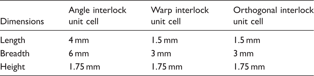
Geometrical dimensions of 3D woven fabric unit cell.
Two software that have been used are
Solidworks 2011
To create 3D structures of woven fabrics which can further be used to determine the impact properties. SolidWorks is a parasolid-based solid modeler, and utilizes a parametric feature-based approach to create models and assemblies. Parameters refer to constraints whose values determine the shape or geometry of the assembly. Parameters can be either numeric parameters, such as line lengths or circle diameters, or geometric parameters, such as tangent, parallel, concentric, horizontal or vertical etc. Numeric parameters can be associated with each other through the use of relations, which allow them to capture design [14].
ANSYS
To determine various parameters such as total deformation, maximum stress and equivalent strain of the structures created in Solidworks. ANSYS Inc. is an engineering simulation software (computer-aided engineering, or CAE) developer. It offers engineering simulation solution sets that a design process requires. Companies in a wide variety of industries use ANSYS software. The tools put a virtual product through a rigorous testing procedure (such as crashing a car into a brick wall or running for several years on a tarmac road) before it becomes a physical object. It has applications in various fields such as automotive, aerospace, electronics etc. [15].
The structures of multifilament 3D fabric unit cells created using Solidworks are shown in Figure 1.
Structure of kevlar 29 (multifilament, 1500 denier yarn, 15 denier- fiber) 3D woven (a) orthogonal, (b) angle interlock and (c) warp interlock fabric.
The macroscale structures of 3D woven fabrics formed by repeating these unit cells are shown in Figure 2.
Macroscale structure of 3D woven (a) orthogonal, (b) angle interlock and (c) warp interlock fabric.
Mesh formation
In a woven architecture, the tows/constituent yarns cannot remain with circular cross-section. Due to deformation of shape, they get flattened. For theoretical analysis and understanding, many models have been suggested. Among those the racetrack and elliptical shapes are most common. The race track shape which is a flattened cross-section with semi-circular sides is most close to the practical values. This has been established by many researchers. Therefore in our study a race track cross-section is considered. However, the individual filaments are considered to have their original circular cross-sectional shape. For purpose of simplifying the model and minimizing number of nodes as well as the number of elemental structures, the yarns are treated as isotropic. As per previous research work reported, the race-track cross-section modeling is more appropriate for practical validation.
Yarn dimensions are the major axis = 1 mm, and the minor axis = 0.7 mm.
Meshing paramaters.

The general image of meshed 3D woven fabric is shown in Figure 3.
Mesh formation in 3D woven fabric.
Boundary conditions
The following boundary conditions are maintained while modeling the 3D woven structures for impact simulation.
Fixed and frictionless support
The composite structure in our study consists of specially designed 3D woven fabrics impregnated with epoxy resin. It is assumed that the reinforcing fibers/tows are surrounded by the matrix molecules from all sides and there exists a strong interfacial bonding. While doing the theoretical analysis for understanding the deformation of the fibers and the woven architecture, it is therefore considered to be a frictionless surface of the tows. It means that there is no lateral displacement of the tows with respect to the matrix. Under such assumption, it is possible to predict the total deformation of the model. To prevent the distortion of unit cell, surfaces are provided with frictionless support so that there is no motion in the direction perpendicular to the surface.
The unit cell can be considered as combination of two symmetrical halves on both sides of the central plane. These are identical halves and mirror image of one another. Second assumption is that, there is no relative displacement between the two halves of the unit cell [17]. The plane of symmetry will not move, if equal and opposite forces are applied on the surface of the unit cell. Therefore, the unit cell is divided by this plane of symmetry and one side is welded with fixed support to prevent the rigid body motion. Fixed support has been given to all three sides of the 3D woven fabric composite which can be seen in Figure 4.
Fixed support on all sides supported by matrix.
Direction and point of application of force
Figure 5 shows the direction and point of application of impact force. The arrow shows the face of 3D woven fabric composite where impact force is applied.
Direction of application of impact force.
Assumptions
The cross section of yarn is taken to be race track to draw more realistic models. Isotropy: Properties like tensile modulus, Poisson’s ratio and tensile strength are considered uniform in all directions. Composite material consists of 55% (v/v) kevlar fiber and 45% (v/v) epoxy resin is assumed to be homogenous in nature.
Preparation of experimental samples
Three different structures of 3D woven fabrics e.g. orthogonal, angle interlock and warp interlock were developed with following specifications. Stuffer warps/m 500, binder warps/m 300 and wefts/m 900. Areal density is 1350–1420 g/m2. The CCI sample weaving machine was considered to be the best suitable loom for this purpose. Some modifications in the conventional loom made it possible to weave 3D fabric with existing loom. A separate negative let off arrangement was made behind the loom to hold binder beam while preparing 3D woven fabrics. All three solid woven structures viz. orthogonal, angle interlock and warp interlock were prepared on the same machine [18,19]. The beams required to feed this loom were prepared on the CCI sample warping machine. The samples are shown in Figure 6.
Experimental samples of 3D woven fabrics (a) orthogonal , (b) angle interlock and (c) warp interlock.
Compression molding
All composite samples were prepared by compression molding technique. Epoxy resin was used as a matrix component for all the fabrics. The principal advantage of compression moulding is its ability to produce parts of complex geometry in short period of time. SANTECH compression moulding equipment is used to prepare composites [20]. The parameters set on the machine while preparing composites are curing time 900 sec, breathing pressure 8 N/m2, curing pressure 18 bar N/m2 and curing temperature 140℃.
Specifications of 3D woven composite samples
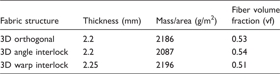
Specifications of 3D woven kevar-epoxy composite samples.
Impact testing of experimental samples
In order to establish a correlation and to check the validity of the predicted results, impact tests were also conducted using ASTM D3763 standard test method [21]. The Fractovis free fall drop impact tester was used for this purpose. Though the test involves a drop impact method instead of a projectile impact method, the results are supposed to give some understanding of the load distribution and failure mechanism. Impact force was varied from 2000 N to 15,000 N. The instrumental set up is shown in Figure 7.
Fractovis free fall drop impact tester.
Results and discussions
Total deformation in 3D woven kevlar-epoxy composites
Finite element loads are independent of the mesh configuration. One can change the element mesh without affecting the applied loads. This allows mesh modifications and conducting mesh sensitivity studies without reapplying loads each time. Therefore, selecting a model and applying loads on the elements is much easier than other methods. Elements generated by ANSYS meshing commands are in the active element coordinate system. Nodes generated by meshing commands use the global Cartesian coordinate system. Therefore, the finite element model can have different coordinate systems and loading directions. In the proposed model, the authors are analyzing the failure prediction of 3D woven structures used as reinforcement in polymer composites. The types of stresses coming into picture in a practical situation are tensile, compressive, shear and bending. Thus, the structure is subjected to deformations in all modes. The fibrous structure will have deformations in x, y and z directions. The total deformation is calculated as resultant of all axial deformations. Total deformation in the 3D fabric composites for an impact force of 15,000 N are shown in Figures 8 to 10.
Total deformation caused in 3D orthogonal kevlar-epoxy composite. Total deformation caused in 3D angle interlock kevlar-epoxy composite. Total deformation caused in 3D warp interlock kevlar-epoxy composite.


In 3D fabric composite impact situation, when stress is generated in the transverse direction, there is a lateral deformation. In this case, stuffer yarns experience the compressive load. Among the load options available in FEA, pressure load is more suitable for analysis purposes as compared to point load, so that uniform force can be distributed on each stuffer yarn. The deformation during impact situation is partly elastic and partly inelastic. The total deformation is calculated as resultant of all axial deformations. The ANSYS software performs such calculations while predicting the stresses and strains.
Simulation of three different 3D woven kevlar epoxy composites was carried out to predict the amount of stress, elastic strain and total deformation generated under the action of impact. It is clearly stated from the above results that the amount of equivalent stress, equivalent strain and total deformation generated in 3D orthogonal fabric is the least and angle interlock 3D fabric experiences much higher values of the same under impact force. The analysis has been done at three different impact times and for each impact time five different values of forces have been chosen. Total maximum deformation, equivalent strain and equivalent maximum stress (impact force) generated on these composite samples have been noted. Results are shown for three different impact times in Figure 11.
Total deformation vs impact force in 3D woven kevlar-epoxy composites.
Simulation of three composites made from three different fabric reinforcement structures suggest that 3D orthogonal fabric is most suitable for composite applications as it shows maximum resistance to deformation under impact.
The angle interlock fabric reinforced composite shows highest load-bearing capacity. This can be attributed to intensive inter-yarn friction generated in the structure due to interlacing binder threads. The deformation behavior shows that orthogonal structure bears maximum load against a minimum deformation. This kind of structure involves uncrimped yarns in filler and warp. Therefore, the yarns are not as extensible as in interlaced crimped yarns in other two structures. Thus maximum transformation of axial properties is achieved in case of 3D orthogonal fabric reinforcement.
It is observed that a smaller impact time results in a lower level of deformation and higher impact force. On the other hand, a longer time of impact allows for a higher deformation associated with lower impact force in the 3D fabric reinforced epoxy composite system. It may be due to a prolonged time available for the displacement of constituent yarns/tows in the reinforcing 3D fabric.
Experimental validation
The developed composite samples were evaluated using the Instron Dynatup Impact Tester. The results were compared against the predicted values of impact force and total deformation. The strain in the composite samples investigated in maximum 5.5%, which is observed in case of 3D warp interlock fabric reinforcement. The strain in 3D angle interlock fabric reinforced composite is 1.7% and that in orthogonal fabric composite is less than 1%. The lowest deformation (strain %) in orthogonal structures is attributed to the uncrimped filler yarns.
For each category 10 samples were evaluated. The results obtained have maximum coefficient of variation of 8%. Thus a statistical significance is observed.
It is shown in Figures 12 and 13.
Correlation of predicted and experimental maximum impact force for 3D woven kevlar-epoxy composites. Correlation of predicted and experimental maximum deformation for 3D woven kevlar-epoxy composites.

It is visible from the results that the simulated maximum impact force and total deformation are well correlated to the experimental values. A higher value of deformation implies that the sample can absorb more impact energy and has better impact tolerance. In accordance with the trend of prediction, the orthogonal structure-based composite shows maximum impact resistance whereas the angle interlock fabric composite shows minimum resistance accompanied with a maximum deformation. This is due to uncrimped disposition of filler yarns in orthogonal structures and the relatively higher amount of crimp present in angle interlock structure.
There are data points far away from the average line in Figures 12 and 13. In fact an experimental 3D woven structure has much higher degree of anisotropy as against the ideal conditions assumed while modeling of the geometry. This leads to a big difference in the composite properties after impregnation with epoxy resin. Moreover, some of the voids are unavoidable in practical conditions as compared to a void-free composite in theoretical prediction. The experimental data for Kevlar-epoxy composites shows a CV of 8%. However, the error of prediction is higher.
There is a nonlinearity observed in the figures. The theoretical model assumes the tows/yarns as ideal engineering materials, whereas, Kevlar yarns are viscoelastic in nature. The stress–strain behavior of fabric reinforced composites is not linear and the deformation is caused in different phases. First there is decrimping of the constituent yarns followed by filament extension and then the interfacial shearing. Thus, the behavior does not follow linearity like metal elements.
Conclusion
Simulation of different 3D woven kevlar fabric-based composites was done with varying level of impact forces for different time intervals in order to calculate their corresponding maximum total deformation and maximum impact force. The total deformation in 3D angle interlock kevlar-epoxy composite is maximum, therefore for ballistic purposes it should be preferred to accommodate the maximum impact load. In 3D orthogonal fabric composite, there is no crimp in the filler yarns, therefore showing least possibility to accommodate stress and strain. These fabric structures will increasingly gain acceptance due to their attractive specific performances and low cost in use for the technical textiles such as defense and civilian areas as transportation, automobile, energy and marine industries. Biaxial, triaxial and more sophisticated multiaxis 3D fabric structures can be used as structural elements in medical, space and rocket propulsions. Examples of these elements are plate, stiffened panel and beams and spars, shell or skin structures, hip and medical devices and prosthesis. The effect of using nano-fillers in addition to high modulus fibers in 3D fabric composites can be explored. Also, further simulation can be done at a microscale structure so as to reach closer to experimental results. Experiments should be done with these fabric structures made from various high-performance fiber materials and suitable matrix combination.
Footnotes
Declaration of Conflicting Interests
The author(s) declared no potential conflicts of interest with respect to the research, authorship, and/or publication of this article.
Funding
The author(s) disclosed receipt of the following financial support for the research, authorship, and/or publication of this article: This work was supported by project No. L1213 of program NPU in Czech Republic.