
Abstract
In the wind energy sector, automotive and aviation industries, non-crimp fabrics have been established for many years. Non-crimp fabrics are also increasingly being sought in the construction sector. Due the connection to the concrete, the non-crimp fabrics with a grid-like open structure are used as textile reinforcements. This paper presents the development of alternative stitch-free bonding technologies for non-crimp fabrics based on multiple carbon fiber heavy tows for textile-reinforced concrete components. For this purpose, an initial analysis is carried out to find out the effect of impregnation on the number of roving layers. Further examinations to determine the process-related limits and mechanical process parameters for using this kind of rovings in textile machines are performed on the influence of multiple roving tension on changes width. Finally, the strength of the bonding points of the non-crimp fabrics produced in a laboratory scale is thoroughly investigated by varying the grid geometry, number of roving layers and bonding technology. The investigations show a good potential of the developed bonding technologies for the production of alternative bonded stitch-free non-crimp fabrics. Compared to grid-like open structures, which are connected by stitching threads, the strength of the bonding points can be increased up to 30%, by the developed stitch-free bonding technologies.
Introduction
The growing global population increasingly puts the topic of resource efficiency at center stage for companies and researchers alike. However, in the wind energy sector, automotive and aviation industries, non-crimp fabrics (NCFs) have been established for many years [1–4]. NCFs are also increasingly being sought in the construction sector. Innovative developments in concrete materials are crucial, as concrete is the second-most important resource consumed worldwide next only to water [5].
Textile-reinforced constructions, especially those made from high-performance materials like glass or carbon fibers, have enormous potential to save concrete compared to conventional steel-reinforced constructions. They allow the construction of thin-walled, lightweight and yet highly loadable concrete components [6]. In addition, there are several applications of textile reinforcements for the renovation of existing buildings [7,8].
In 2014, the first general approval by the building inspectorate in Germany was granted for textile reinforcements for the strengthening of ferroconcrete. These approved reinforcement structures are produced based on multiaxial warp knitting technologies (see Figure 1). The bonding between the carbon fiber roving reinforcement layers in the NCF, which are arranged in 0° and 90° directions, is ensured by means of a textile warp knitting process using stitching threads [9]. This stitching thread fixes the position of the reinforcement yarns during the processes following textile fabric formation, such as coating, drying, and curing, and even concreting.
Reinforcement structure bonded by stitching threads, also referred to as approval non-crimp fabric (0° direction: 50 K carbon roving, 90° direction: 12 K carbon roving).
As mentioned by Al-Monsur et al.[10], there are several disadvantages of bonding the reinforcement yarn layers in NCF by means of a stitching thread. These include first of all insertion and damaging of the 90° yarns by the warp knitting needle as a part of the established weft insertion process, which is not adapted to the stitch course direction. Secondly, partial thickenings of the reinforcement yarn material, which causes additional shear forces under tensile loads in the concrete component. As a result concrete flaking and cracks in the finished composite part can occur [1,10,11]. This means that the omission of stitching threads will help reduce shear forces in the component by reducing the thickenings in the textile plane [1].
For a sufficient transfer of the forces from the composite in the reinforced textile structure and the utilization of mechanical properties of the rovings, a coating that will completely impregnate the rovings is necessary for the purpose of bonding individual filaments. So that a maximum number of filaments is involved in the load transfer for a proper utilization of the loading capacity of a textile reinforcement. Furthermore, other goals of a coating of textile reinforcements are to increase the adhesion between concrete and fibers. The coating stabilizes the geometry of the structure during concreting and ensures protection of the fibers against environmental influences [1,12]. More information about the influence of the coating to the mechanical properties of the rovings is given in Cherif [1], Köckritz [12], Jesse et al. [13], and Younes [14].
Due to the partial high packing density of the bonded rovings as a result of the warp knitting process, the produced NCF is harder for the coating agent to penetrate than uncompacted rovings. In addition, the stitching threads create an additional flow resistance during coating, due to the fact that the stitching threads lie on the surface of the rovings. To overcome these restrictions, the bonding of the rovings within the NCF without a stitching thread, based on coating or adhesives is a promising solution. Textile structures, which are produced without the stitching threads are subsequently declared thereafter as the stitch-free NCF [10].
The stitch-free NCF will be particularly advantageous when the existing limitations of textile processability of the warp knitting process especially for the production of reinforcement structures with large roving cross-sections can be addressed. Because to realize heavy-duty, textile-reinforced buildings, a suitably loadable reinforcement structure is necessary. Useful summaries on the effect of the load bearing capacity of concrete through textile reinforcements are given in Berger et al. [11], Jesse et al. [13], and Schladitz et al. [15].
The textile can contribute to the dissipation of high loads with an increased degree of reinforcement in the textile concrete composite component. The lower dissipation of textile structures can be achieved by stacking several textile reinforcement layers or by increasing the roving cross-section of a textile reinforcement layer, through producing multiple roving layers [11,13,15,16]. Regarding the use on construction sites, the second option is preferable due to its smaller processing effort, as only a single textile reinforcement layer has to be handled and embedded in concrete.
Furthermore, the gap between the warp knitting elements is a limiting factor for the processing of multiple roving layers, depending on the machine's fineness.
The bonding of the multiple rovings to the production of a stitch-free textile surface can basically be achieved by form-fit (e.g. bonding between the rovings by ondulation), force-fit (e.g. bonding between weft and warp yarn in an uncoated conventional stitch-bonded NCF in yarn direction) or substance-fit (e.g. by partial melting of two thermoplastic rovings or bonding of rovings by adhesives) [10,17,18]. In order to obtain stretched and stitch-free rovings in the NCF, this research work focuses the substance-to-substance bonding for development of alternative stitch-free bondings for NCF made of multiple rovings. Regarding substance-to-substance bonds, as mentioned by Hausding [19], there are two principals based on cohesion and adhesion. A substance-to-substance bonding by means of cohesion can be created without an additional material, i.e. without a bonding agent [18,20]. This means that the fiber surface must be treated chemically to create a bonding without any interfaces. Apart from the extra effort, a chemical treatment can reduce mechanical properties like Young’s modulus or tensile strength, described by Fuchs and Albrecht [21]. On the other hand, the substance-to-substance bonding based on the chemical principle of adhesion is created by intermolecular forces between the roving and a bonding agent, e.g. a coating or an adhesive [19].
Based on the above knowledge, alternative bondings for the production of stitch-free NCFs made of multiple Carbon Fiber Heavy Tows are being currently developed and validated, in order to achieve improved mechanical properties. In this paper, fundamental investigations done on the effect of number of roving layers on impregnation are presented. In addition, analysis of width changes under tensile loads was also carried out. The focus of the experiments is the characterization of the grid stability of these structures with different bonding methods.
Experimental
Multiple rovings based on carbon fiber heavy tows
For high-load structures, a correspondingly load-bearing reinforcement structure is necessary. Stitch-free NCFs made of multiple carbon fiber heavy tows (CFHT) meet this requirement [10]. The goal is to produce multiple roving layers which are brought together by a parallel placement of individual CFHTs on a sleeve (see Figure 2(a)), using a winder. It is to be mentioned here that multiple roving layers can be also produced by twisting or using a wrap yarn [22], see Figure 2. The variant b in Figure 2 (twisting) as described in Zhang and Miao [23] and Thommanny and Ermanni [24] is unsuitable for the production of CFHT bundles for textile reinforcements due to the possibility of damages of the shear force-sensitive CFHTs, and the greater elongation of the twisted reinforcement structure under tensile loads, which may cause cracks in the concrete [1]. The use of wrap yarns (c in Figure 2) results in partial thickening on the roving surface, similar to conventional NCFs, which can later lead to local flaking in the textile concrete.
Depiction of various bundling variants, in order to produce multiple roving layers according to Gebuhr [22].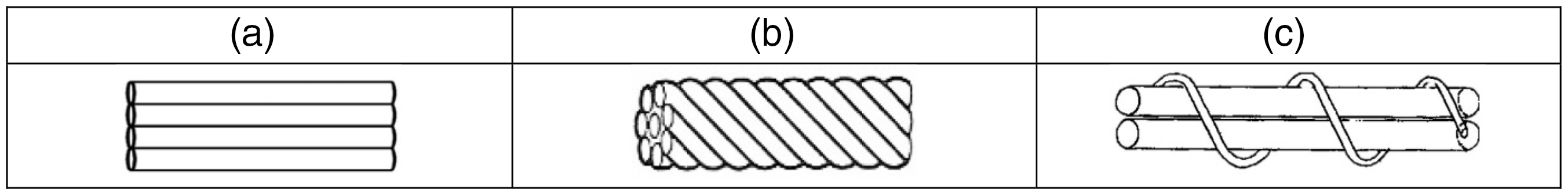
Up to six bobbins (6 × 50 K) are fed to the winder off a creel. After the CFHT are run through an eyelet matching the geometry of the bundling, they are tangentially wound up on a sleeve. However, multiple roving layers (number of filaments >50 K) are not available on the market.
Textile parameters of the produced multiple rovings.

Overview of samples.

RS: reference sample, PS: pattern sample, a: bonded by coating agent styrene butadiene dispersion (SBR), b: bonded by coating agent SBR and adhesive.
Initial test on the effect of number of roving layers on impregnation
The basis for the performance of several roving layers made of CFHT is a complete impregnation [11,12,16]. To determine the impregnation behavior of multiple rovings, coating tests are performed. The following three methods are selected (Figure 3), based on common coating processes in textile applications:
Overview of impregnation methods (I: Dip coating, removal via roller squeezing unit, II: Kiss coater, III: Dip coating, removal via nozzle), according to Giessmann [25]. I: Dip coating with a cylindrical squeezing unit (foulard principle), II: Kiss coater, and III: Dip coating with subsequent squeezing by means of a nozzle adapted to the thickness of the CFHT.
To prepare the coating tests according to the multiple rovings, the gap between squeezing rollers is adjusted to method I, while individual nozzle diameters are selected based on the number of roving layers for method III. The preselection of gap size and nozzle diameter is made based on equations (1) and (2).

where
Operating under the theoretical assumption of a circular cross-section, the roving diameter is calculated using equation (2)

where
The calculation of the roving diameter using equation (2) considers neither an applied sizing nor coating material contained in the roving. Therefore, the calculated values are only approximated to adjust the settings of the coating apparatus. The fine-tuning of the nozzle diameters/squeezing roller spacing is made iteratively to optimize the achievement of a coating agent content of 13 to 18 mass percent, as specified by the approval of the building inspectorate [5]. The aqueous styrene butadiene dispersion offered by Lefatex-Chemie GmbH as Lefasol VL 90/1, with an addition of Lefasol VP 4-5 LF curing agent is used as the coating agent for these tests. To gain first insights into the impregnation of multiple rovings, 2 × and 6 × roving layers are subjected to coating tests. For the interpretation of the impregnation behavior depending on the number of roving layers, microsections of the multiple roving segments are prepared. For this purpose, the cross-section of the multiple rovings cut transversely to the fiber direction is embedded. Subsequently, the side of the microsections to be microscoped is grounded in several machining steps and finally polished. The microscopic analysis is then performed by means of an incident light microscope at 25 × magnification.
Analysis of width changes under tensile loads
The experiment is important to gain the information regarding on the one hand for the design of the roving guiding elements of the textile machine and on the other hand for the resulting intermediate spacings of the lattice structure.
The width of the rovings is examined as a function of the tensile force in the longitudinal direction of the roving. The cross-sectional shape of the rovings, in particular the 0° rovings, also called warp yarns, changes if no stitching thread (stitch-free) is used, see Figure 3. The cross-section of the roving in a conventional NCF is approximately circular (Figure 3, left). Eliminating the stitching thread, the rovings are not compressed in width direction, this changes the cross-section to an elliptical shape (Figure 4, right). Therefore, in the following discussion, rather than diameter, width is referred.
Schematics for the position and cross-section geometry of rovings with circular (left) and elliptical cross-section (right).
Further information regarding the grid structure is included in section “Production of stitch-free non-crimp fabric (NCF) of multiple roving layers”.
The measured values in the nearly unloaded state of the roving bundle with a pretension force of 0.1 N are referred to Figure 9. A yarn tensiometer (F ≤ 1 N) is attached to the opposite side and pulled during the tests. The resulting width of the CFHT is measured by a digital measuring slide at three locations, ¼, ½, and ¾ of the distance between the tensioning of the roving to the point of application of the yarn tensiometer gauge (see Figure 5). During the measuring, the jaws of the measuring slide are pushed together until contact with the roving occurs. In this case, there shall be no compression of the roving. The measurement accuracy and resolution of the used digital measuring slide are 0.01 mm.
Test setup to measure the width of CFHTs under tension load.
Production of stitch-free NCF of multiple roving layers
Stitch-free NCFs made of multiple roving layers are not available in the market. For the analyzation of their bonding points, stitch-free NCFs made of multiple roving layers are produced in a laboratory scale.
The production of stitch-free fabrics is carried out on the basis of the substance-to-substance bond, using the principle of adhesion as described in section 1 (i. e. bonding of the rovings by coating, and bonding of the rovings by coating and additional adhesive). In addition, the selection of the number of roving layers gained from the results of the impregnation properties from subsection Analysis of initial test on the effect of number of roving layer on impregnation.
According to Category 1 contains the so-called asymmetrical reference samples (rectangular textile grid opening). Their geometry and fiber material selection is based on the approval NCF (see Figure 1 and Table 2). Category 2 comprises the symmetrical pattern samples (square textile grid opening). Here, the spacings between reinforcement yarns in 0° and 90° direction are identical. The 0° direction is the direction of production, also referred as the warp yarn direction. The 90° direction refers to the weft yarn direction.
By increasing the number of roving layers, the axial distance between the CFHT bundles has to be increased in order to avoid the delamination between fibers and the concrete [27]. According to Jesse et al. [13], the ratio of openings in comparison to the total area of the reinforcements has to be at least 50%.
The fixed axial distances (grid opening widths) of the pattern sample in Table 2 are based on this assumption and the calculation made by the Institute of Concrete Structures at TU Dresden (see Equation 3). From the experience of previous study, the bond strength 
where
In summary, identical distances and yarn fineness in warp and weft direction are selected. Thereby, textile reinforcing structures are provided, which allow symmetrical load removal and easy handling on the construction site, since there is no preferred load direction. Such textile structures are referred to as pattern samples in the following discussion. These pattern samples consist of multiple rovings (filament count >50 K). The production of the samples is done manually with the help of test equipment on which the CFHTs can be manufactured based on a defined resolution, see Figure 6.
Representation of the developed testing equipment and the process chain for the production principle for the manufacture of stitch-free non-crimp fabrics (NCF).
It is to be mentioned here that with the test equipment, the coating application is not possible in a continuous process as in the impregnation tests carried out in section 2.2. But on the basis of the impregnations findings depending on the number of roving layer from section 2.2, the scope of the test is determined. Furthermore, the selection of the method for manual coating process is based on this. The coating is carried out from both sides of the stitch-free NCF by manual lamination process, in which case the yarns are squeezed in a flat manner similar to coating processes-I (Figure 3). The activation of the coating with styrene butadiene (SBR) is carried out by a convective drying process at about 150℃.
The samples are produced in the following two ways:
Bonding method a: The coating agent is applied to the sample, after the weft and warp yarn are completely stretched onto the frame (Figure 6). For this purpose, styrene butadiene (SBR) dispersion with an addition of a curing agent (as used in section 2.2) is applied. Bonding method b: After placement of the weft yarns, the copolyester hot melt adhesive Griltex® D 2351 E CoPES (CE 21) by EMS-CHEMIE HOLDING AG is used to bond the yarn layers [10,26]. The thermoplastic adhesive material is found very suitable for a multilayer-adherence in the field of composite preforming [26]. The adhesive is applied by means of a pipette, immediately before placement of the warp yarns. The thermoplastic adhesive is activated by heat input, the melt application temperature is between 160 and 200℃.
In both methods, a coating agent application takes place at the end of the production of the stitch-free NCF. All samples are prepared with electric scissors, removing samples of 150 mm in length from the NCF. The width is the distance of the two vertical CFHTs. An overview of the samples is given in Table 2.
Characterization of grid stability of stitch-free NCF
It is the goal to evaluate the developed bonding types with regard to the strength of the bonding points. Regarding the required suitability of the stitch-free, open NCFs for construction sites, the strength of the bonding points of the individual reinforcement yarns within the NCFs is an essential indicator for the practicability of the developed stitch-free fixed NCFs. The bonding strength is directly related to the displacement stability (grid stability) of the textile structure. Therefore, the strength of the bonding points in the approval NCF (see Figure 1) is used as a guide value for the characterization of grid stability of stitch-free NCF textile structures.
It is to be mentioned here that the failure and peel behavior of flexibly/rigidly glued samples are conventionally determined based on standard DIN EN ISO 8510-2 [28]. The test setup described in the standard does not allow an examination of the bonding point strength of grid-like NCF based on warp-knitting technology [28]. To be able to examine both NCF fixed by bonding agents (adhesive/coating agent) and by stitching threads, a new method is developed at the ITM (see Figure 7).
Schematics for the developed testing rig for an analysis of grid stability in open non-crimp fabrics (NCF).
Using the testing rig, the influence of the fixing method or bonding variation on the course of the resulting force and the deformation behavior of the roving during the testing process will be examined until a failure of the bonding point occurs. It is assumed that the peak of the recorded force-strain line corresponds to the failure of the bonding point, see Figure 11. The breaking force (F) acting at that moment is the maximum tension Fmax of the corresponding test series.
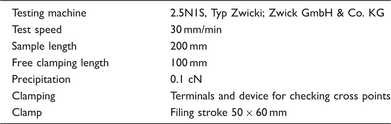
Test parameters for the determination of bonding point strength.
The developed testing regimen shown in Figure 7 is capable of loading two bonding points in each test. The blue dots represent the area of the bonding points in Figure 7. Due to the rigid clamping on the bottom side of the sample, the points are only loaded during the vertical upward motion of the upper mounting fixture. The mounting fixture is fit with a clutch, which grips into the grid opening of the textile structure underneath the vertically placed roving. The width of the upper mounting fixtures is designed to place the support points as close as possible to the vertical rovings. Therefore, shear strains, momentum in the bonding point, and additional failure influences like torsional flexural buckling are reducing.
The evaluation of the cross point strength tests is carried out on the basis of the determination of the breaking forces (see subsection 3.3).
Two configurations are possible for the test direction:
Test direction 0° means that the 0° roving in the NCF (also called warp yarn) is placed transversely to the direction of the tensile force. Test direction 90° means that the 90° roving in the NCF (also called weft yarn) is placed transversely to the direction of the tensile force, see schematic in Figure 14.
The stitch-free samples of the test series “reference sample” (RS_01/03) are compared to the approval NCF regarding the strength of the bonding points in 0° and 90° directions.
The samples of test series “pattern sample” (PS_08-13) are then examined, with the variant of multiple rovings as an additional parameter.
Results and discussion
Analysis of initial test on the effect of number of roving layer on impregnation
As a result of these preliminary tests, method I (foulard with flat squeezing) and method III (foulard with circular squeezing) are selected from among the coating methods shown in Figure 2. The Kiss coater is not followed further (method II), as the rovings even with 100 K show insufficient impregnation. This statement is made based on observations carried out during the preliminary coating tests, with primarily the side of the roving bundle facing away from the coating rollers showing uncoated areas.
Therefore, the samples produced using coating method I and III are examined regarding the influence of the coating agent styrene butadiene dispersion (SBR) in the roving cross-section (degree of impregnation) by means of microscopic microsection analysis. Methods I and III are significantly different from the squeezing method. For method I, the rollers create a flat roving cross-section, method III creates a circular one with the nozzle.
Figures 8 and 9 show representative CFHT sections, depending on the number of rovings (two or six) and the impregnation, respectively, squeezing method (flat or circular squeezing).
Microsection segment of carbon fiber heavy tows (CFHT) coated with styrene butadiene dispersion (SBR) with flat squeezing (Variant I), left: CFHT 100 K, right: CFHT 300 K.
The microscopic analysis is evaluated on the following basis. The grey area outside of the roving cross-section consists of epoxy resin, into which the CFHT are embedded for microsection preparation. The white areas represent the individual filaments. The coating agent looks dark grey to black in the incident light microscope view. For the microscopic analysis, several consecutive samples are taken from the respective coated CFHT. In Figures 8 and 9, representative microsection segments of these analyses are presented. The microsection segments show that the CFHT (100 K and 300 K) have a better penetration with SBR in core direction, if using coating variant I.
SBR coating agent content of the microscope-analyzed samples.

SBR: styrene butadiene.
After assessing the microscopic analysis results of the microsections, the following results are generated:
The degree of impregnation in the samples produced using coating variant I is higher than in samples produced by means of variant III, due to the lower required depth of penetration with SBR. A complete impregnation of 6× roving layers in one step is not feasible with either variant I or variant III. Furthermore, for the best possible impregnation of the rovings, squeezing methods which convert the rovings into a flat elliptical cross-sectional shape should be preferred.
On the basis of the experiments carried out, in the further investigations, roving layers consisting of 50 K (1× roving layer) and 100 K roving (2× roving layers) are considered. In order to assess the influence of even higher number of roving layers on the grid stability or bonding point strength investigated in subsection 3.3.2, textile structures made from 4-roving layers (200 K) are also produced and considered.
Effect of tensile load on width change of multiple CFHT
The cross-section of non-multiple roving layers and multiple roving layers is flat and wide without tensile loads. Increased tensile loads change the cross-section towards a more elliptical shape, i.e. increased thickness with decreased width. The diagram in Figure 10 contains the measured mean values of the individual test series.
Microsection segment of carbon fiber heavy tows (CFHT) coated with styrene butadiene dispersion (SBR) with circular squeezing (Variant III), left: CFHT 100 K, right: CFHT 300 K. Width change of non-multiple and multiple rovings under tension load.

In summary, it can be stated that a tension load of 1 N reduces the width of the CFHTs to 37% at n = 1, and to 68% at n = 6, compared to the original width in almost unloaded state. The measured values in the unloaded state are referred in Figure 10 as a reference. For reproducible measuring results, these samples are stressed with pretension force of 0.1 N.
Increasing the tensile load to a maximum of 30 N reduces the width to 34% at n = 1 and 54% at n = 6, compared to the original width. This means that an increased tensile force strain causes a more pronounced width contraction. However, the strongest effect regarding a change in width is achieved between the unloaded (reference) and the loaded state. The change in width between the individual loading state (1 N, 5 N, 30 N) is small in comparison to the reference and the test series with 1 N pretension. On the basis of the investigations, a prediction of the roving thickness can be made depending on the number of roving layers and the effective tensile force. Thus, an interpretation of the textile processing process for the production of stitch-free NCF based on multiple roving layers can take place, such as roving spacing or the geometry of the roving guide elements.
Regarding the interpretation of the results, it is important to note that process-related twists, e.g. caused by the roving guiding elements, can alter the resulting widths of the CFHT in the textile processing chain.
Evaluation of stitch-free bonding methods
Reference samples
The diagram given in Figure 11 shows one exemplary sample from each of the corresponding test series carried out to compare conventional stitch thread-bonded NCF (approval NCF) with two different types of stitch-free-bonded NCF. In total, eight samples were tested per series. An overview of mean values of maximum tensile force at which failure occurs is given in Figure 13.
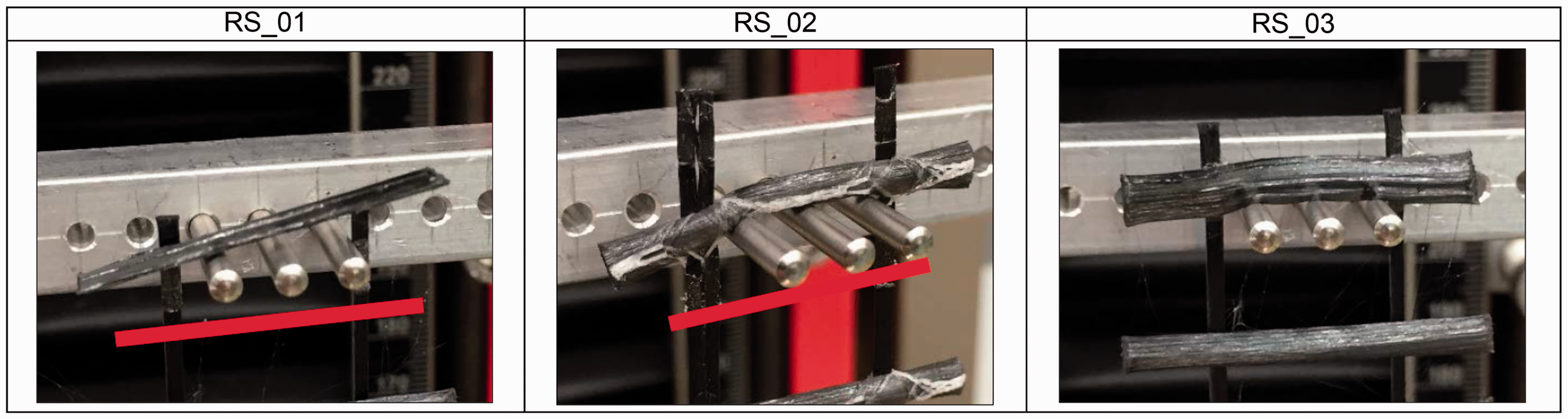
Force-path diagram of selected sample during bonding point tests of the reference samples, fixed by: 01: SBR, 02: stitching thread and SBR (approval NCF), 03: SBR and adhesive. Failure behavior of the fixing points in the reference non-crimp fabrics in test direction 0°, RS_01: fixed by coating agent SBR, RS_02: approval NCF, fixed by stitching thread and coating agent SBR, RS_03: fixed by coating agent styrene butadiene dispersion (SBR) and adhesive. Overview of mean breaking force values at failure of the bonding points in relation to the bonding technology (reference samples). Exemplary failure behavior of the fixing points of stitch-free fabrics (pattern samples), in relation to the bonding technology.


In Figure 12, it can be seen that the slope of the measuring curves in 0° test direction is almost identical for all tested reference NCFs up to a path of approximately 1 mm. This tendency is also present in the course of the measuring curves in 90° test direction, but only for a deformation path of approximately 0.5 mm. The linear slope is caused by the upper mounting fixture deforming the horizontal roving under tensile loads, if the bonding points are not yet displaced. In general, the deformation path up to a failure of the bonding points in the sample is longer in 90° test direction samples than in 0° test direction samples. This behavior is most apparent in samples with RS_02 and RS_03 bonding technologies.
The fixing can fail in several ways. The measuring curves of the stitch-free-bonded bonding points in samples RS_01 and RS_03 show a force reduction in 0° direction immediately after reaching the breaking force. In the complementary test direction, the force reduction after failure of the bonding points is much slower.
Figure 12 shows the distinctive deformation behavior of the samples in relation to the examined bonding technologies in 0° direction. The red mark shows the original position of the roving before load application.
In 0° test direction, the RS_02 samples exhibit a slippage of the warp yarn on the weft yarns (see Figure 12). The stitch formation in the warp-knitting process along the warp yarns does not cause any slippage in the examined samples with 90° test direction. Instead, the bonding point strength is increased. In summary, different failure behaviors are found, depending on the bonding technology. Due to the higher bonding point strength, the rovings of samples RS_02 (in 90° test direction) and RS_03 (in both test directions) are deformed before reaching breaking force, in contrast to RS_01, which is placed perpendicular to the direction of tensile force. Meanwhile, loading of the RS_01 sample causes little deformation of the rovings placed transversely to the direction of the tensile force.
The test results in Figure 13 show that the additional fixing of the bonding points with adhesive can match and even exceed the mean value of breaking force Fmax of bonding points fixed with stitching threads. Fixings made with SBR (RS_01) achieve the lowest forces at failure in the bonding points, when compared to RS_02 and RS_03.
The test results from Figure 13 show that stitch-free-bonded fabrics RS_01 and RS_03 achieve higher tensile force values in 0° test direction than in 90° test direction. This is due to the different yarn finenesses and spacings between the rovings which is: 10.7 mm between the warp yarn (3300 tex) and approximately 14.3 mm between the weft yarns (800 tex). In the tested stitch-free 0° direction samples RS_01 and RS_03, this results in a greater overlap length of the adhesive surface in the direction of tensile force, compared to tests in 90° test direction. This geometric condition significantly influences the achievable breaking force [29].
The fixing with stitching threads, however, causes a higher dissipateable force until failure in 90° direction, as the stitching thread further fixes the position of the weft yarn. In warp direction, the warp yarn can slip along the weft yarn. The stitching thread only prevents the separation of warp yarn and weft yarn, in this case. Mainly, the stability of the bonding points in such samples is determined by the breaking force of the SBR coating. In RS_01 and RS_02, this force is identical in 0° test direction.
Pattern samples
Figure 14 shows the distinctive deformation behavior of each bonding technology with two exemplary samples. In the case of NCFs with rovings fixed by means of styrene butadiene dispersion (SBR), i.e. a, the fixing points fail abruptly by shear. The rovings placed transversely to the load direction of the NCFs fixed by SBR and an additional adhesive display tenacious deformation behavior. Here, the deformation and peeling of the rovings increase with growing tensile force load, until the bonding points fail. In addition, the fractured surfaces suggest that all samples, regardless of bonding technology, exhibit a combination of adhesion failure (between roving and bonding agent) and cohesion failure (within the bonding agent). However, the cohesive share is greater in samples based on bonding technology b (Figure 14).
The described deformation behavior of the pattern samples is based on optical observation and is mirrored by the measured values of the force-path diagram in Figure 15. The pattern samples fixed with SBR show a linear force increase and an abrupt force reduction upon failure of the fixing points. The measuring curves of the pattern samples fixed by SBR and adhesive, on the other hand, display the above-mentioned tenacious behavior, shown by the less steep incline and steadier drop of the force during testing. Additionally, a direct relation between variant of multiple roving and maximum tensile force until failure of the fixing points is apparent. A comprehensive statement regarding the maximum tensile force in relation to the respective fixing and variant of multiple roving is made based on the mean values in Figure 16.
Force-path diagram of selected sample during bonding point tests of pattern sample; nomenclature: Number of roving layers n = 1, PS_08: styrene butadiene dispersion (SBR), PS_09: SBR + adhesive; Number of roving layers n = 2, PS_10: SBR; PS_11: SBR + adhesive; Number of roving layers n = 4, PS_12: SBR; PS_13: SBR + adhesive. Overview of mean maximum tensile force value until failure of the bonding points in relation to bonding technology and number of roving layers (pattern samples). SBR: styrene butadiene dispersion.
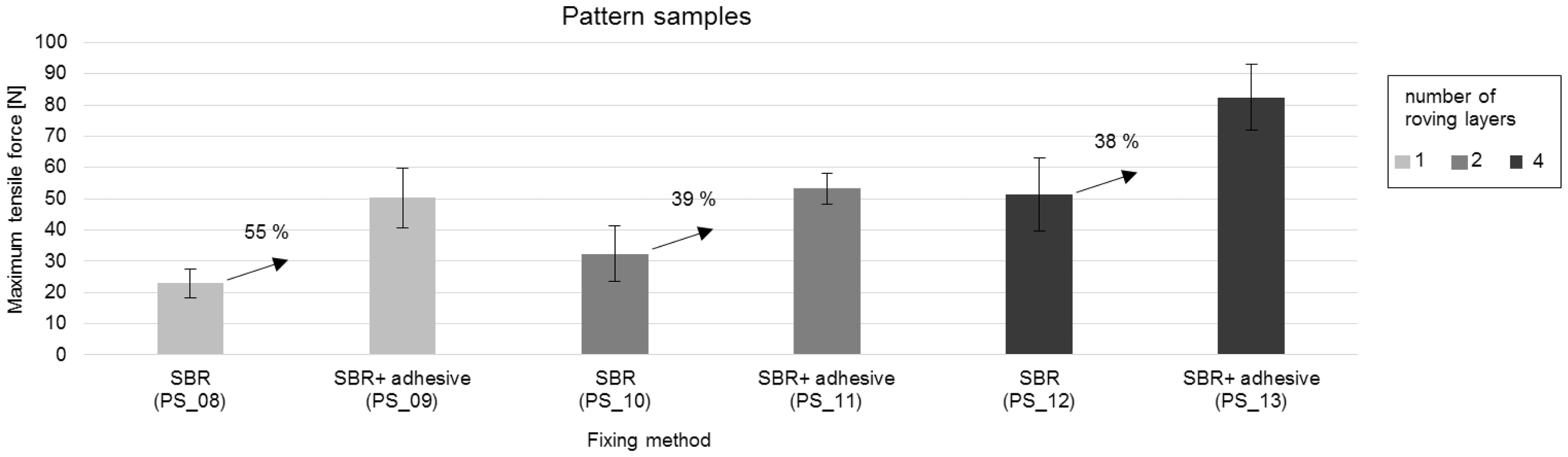
In general, a higher degree of roving layers causes greater area of contact for the fixing agent (SBR/adhesive). Therefore, the higher the degree of roving layers, the higher the breaking force of the bonding points will be. Analogously to examinations of the reference samples, it can be stated that the fixing of the rovings based on SBR and adhesive allows the absorption of much higher tensile forces (up to 55% higher) than for rovings bonding solely by SBR.
Conclusions
The achieved results give a comprehensive overview of the characteristics of alternative, stitch-free bondings between reinforcement layers consisting of multiple CFHT (rovings) for reinforcements in construction applications. Initial tests gave insight regarding the impregnation behavior of multiple roving layers, showing that 6 layers of 50 K rovings does not allow a complete impregnation with the technologies employed. It is also proven that flat roving bundles are more easily impregnated than the circular roving cross-sections.
In addition, an analysis of the influence exerted by tensile forces on the change in width of the roving with varying degrees of number of roving layers is carried out. These results are essential for the design of roving guiding elements on a textile machine. For example, there is an average reduction in the roving width, increasing the tensile force from 0.1 N (pretension) to 30 N by 63%.Approaches to production of alternative, stitch-free-bonded NCFs are provided, analyzed, and realized. Two substance-to-substance bonding types are examined, such as bonding by coating agent and bonding by coating agent with an additional adhesive. The evaluation of bonding points is ensured by a test regime. This encompassing the characterization of developed bonding technologies and derivation of relevant factors for the achievement of satisfactory composite properties between the reinforcement roving layers (rovings). In summary, the measured results show that a substance-to-substance bonding of the bonding points based on a styrene butadiene coating and the additional application of an adhesive creates the most stable bonding. In fact in test direction 0°, the breaking force of bonding points based on a styrene butadiene coating and an additional application of an adhesive is ca. 30% higher as the breaking force of bonding points of NCF using stiching threads. In test direction 90°, the increasing is 4%. However, ensures that rovings even bonded solely by SBR can transfer almost identical loads in weft direction similar conventional NCF.
The investigations will build a solid groundwork for the derivation of machine concepts for the production of alternative, stitch-free-bonded NCF of multiple roving layers.
Footnotes
Declaration of Conflicting Interests
The author(s) declared no potential conflicts of interest with respect to the research, authorship, and/or publication of this article.
Funding
The author(s) disclosed receipt of the following financial support for the research, authorship, and/or publication of this article: This article presents selected results of the IGF research projects 18403 BR/1 of the Forschungsvereinigung Forschungskuratorium Textil e. V., Reinhardtstr. 12–14, 10117 Berlin and is funded through the AIF within the program for supporting the “Industrielle Gemeinschaftsforschung (IGF)” from funds of the Federal Ministry of Economics and Technology (BMWi) by a resolution of the German Bundestag such as results of the BMBF project “Carbon Concrete Composites – basis project 1”.