
Abstract
2D fabrics are used widely and to good effect as a reinforcement for many planer composites and simple curved structures, i.e. a cylindrical arc. There are, however, manufacturing difficulties in the formation of composite structures which are curved across two axes, i.e. a bowl shape. This can be addressed by manufacturing “3D” fabric preforms; however, this requires complex machinery and is slow and expensive. It is, therefore, desirable to form complex curved shapes from planer textile structures; this is either done by cutting a net shape from the textile and placing it on a mold or by using force to stretch the fabric to the mold. These methods, however, result in discontinuous reinforcement or poor distribution of phases, respectively. Wrinkling of the fabric during formation will increase the possibility of composite failure under loading because of the presence of rich fiber or resin areas. A new method was suggested to manufacture 3D shapes from 2D fabric through the application of cyclic loading on the 2D fabric under a continuous hot air till the final fabric prepreg bagging form is reached. The composite fabrication process was completed in two steps: imposing dynamic bagging of the chemically treated 2D Jute fabric with 16% sodium hydroxide in slack form to fit the die final shape prior to the infusing of the resin accompanied by pressing two halves of the mold. A proto-type setup was designed to study the two-step fabrication method for various shapes of 3D fabric reinforcement.
Introduction
The natural fiber composites have several advantages over the synthetic fibers, such as lighter weight, low cost, high specific strength, modulus, and most important – its degradability. Natural fiber composites are used in numerous applications in the automobile, aviation, and construction industries. Each car in average uses about 30 kg of natural fiber composites [1]. One of the problems that facing the consumption of natural fiber composites in the formation of different parts is to avoid affecting the fabric properties or inserting different stresses on the fabric that might cause distortion in the fabric and wrinkling. Also, stringent environmental legislation and consumer awareness forced industries to support long-term sustainable growth and develop new technology based on renewable feedstock. Application areas of jute-reinforced polymer composites were found in the various implementations, like automobile industries, building components, transport sector, due to lighter weight, less raw material, better cost economics, serviceable mechanical properties, renewable resource, and its degradability as a replacement for the use of glass fiber [2]. Today jute fiber is the least expensive fiber of mass consumption, at only a fraction of the cost of glass fibers; in terms of volume, jute is now the second most important fiber in the world, next to cotton. One such avenue is in the area of fiber-reinforced composites [3]. Jute fibers are a quarter of the price of the glass fiber per kg, almost half of its density, as well as the specific strength, and stiffness is 45% [4]. To form the textile composites, there are several routes of manufacturing. Each distinct route has its own specialty and suitability. Some of the most popular manufacturing routes are: spray lay-up, vacuum bagging, filament winding, pultrusion, resin transfer, infusion processes, prepreg molding, low-temperature prepreg, resin film infusion, and wet/hand lay-up [1–6]. The manufacturing of composites often requires the transformation of 2D fabric into various structural 3D shapes through preform processing. It was suggested to create 3D shapes through the bagging of the fabric [7]. Most studies of the bagging phenomena were linked with the garment comfort [8–20], as the bagging performance of knitted fabrics is important to both appearance and mechanical performance. Generally, the bagging is a 3D deformation of a fabric under a force normal to its plane. Nevertheless, the term is used for the permanent deformation of certain parts of a garment, such as the sleeves around the elbow and the trousers around the knee. Bagging results from the lack of dimensional stability or recovery when repeated or prolonged pressure is exerted on a fabric [12]. However, a residual bagging depends on the fabric recovery properties [7]. Many types of research have been conducted on the double curvature 3D forming process of woven reinforcements. When forming a flat woven fabric composite laminate into particularly curved products, the originally orthogonal arrangement of the yarns in the weave becomes highly disturbed during the forming operation [21]. As a result of this reorientation, the thermo–elastic properties of the fiber-reinforced composite material appear a corresponding distribution. The inhomogeneous distribution of the thermo–elastic properties in the product results in a distribution of residual stresses during the production process. These stresses can yield the unacceptable shape distortions of the product. The bagging formation of several types of fabric designs, such as knitted, braided, or nonwoven fabrics, was tested. Each type of fabric has its particular defects. The 3D knitted shapes suffer from the non-uniform thickness and the non-uniform directions of the loops, while nonwoven fabric suffered from the non-uniform orientation of the fibers in x, y, z directions that give variability in-plane shear properties [7]. Braid structure fabrics also have a variation of in-plane shear angle due to the high deformability of braids as a result of the initial orientation of the yarn in the braided structure. The difference between braiding and weaving processes, especially the angle between the yarns, leads to two different textile structures. Consequently, the different formability behavior can be remarked during the preforming [22]. The textile fabric composite process consists of draping a dry preform before injection of the liquid resin. The mechanism of deformation that takes place during the preforming stage is complex and very different from the ones occurring during the stamping of metallic sheets, and these mechanisms are far from being fully understood [21–23]. Similar to sheet metal forming, woven reinforcement is placed between the die and blank holder and a punch pushes the woven fabric into the die cavity to form it to the desired geometry. The production of defect-free parts at a reasonable cost requires a fundamental knowledge and systematical understanding of the deformation of textile reinforcement during the manufacturing process, and the effects of weave pattern and blank holder load on the maximum tensile stress of the yarns. The maximum stress is increased by blank holder load in all weave patterns because more friction force is applied to the layer between the die and blank holder surfaces. Friction force resists against the radial displacement of the yarns as the punch moves into the die cavity during forming process [24,25]. In this case, the construction of the woven fabric (the way the yarns are arranged in the fabric structure) provides the ability of the reinforcement to be deformed by the in-plane shear mechanism [26]. Moreover, the material sensitivity analysis highlighted the effect of two factors: the friction coefficient between yarns and the transverse stiffness of the yarns. Similar to the geometrical factors, these results were related to the kinematics of deformation during fabric shearing. Before locking, yarns may slide on each other, and therefore the effect of friction is important. After the initiation of locking, adjacent yarns come to a side-to-side contact; the interaction between yarns in the contact region becomes the main source of total reaction force [27] and the relative orientation between yarns of each ply may involve high variations of the tangential friction forces. It can also lead to manufacturing defects, such as unweaving or wrinkles. Whatever the type of pattern, both the weaving parameters and the yarn thickness and cohesion are of primary importance [28]. When using a constant value of the load, the fabric sheet should be subjected to the high value of the load applied to the plunger to produce sheet stretch [29]. Several investigations indicated that the heating of the bast fibers increases their strength, the thermal degradation temperature of the bast fiber starts around 140–200℃ [30,31]. Flax fibers and their composites have shown significant improvement on the thermal degradation temperature of a chemical treatment or grafting co-polymer on the flax fiber surface. The effect of cyclic loading on the bagging of fibers structures was recently investigated [32]. Weight loss of the flax fiber is also reduced by chemical treatment [32–34]. Low density, high specific strength, Young’s modulus, low cost – all these potentialities make natural fibers particularly suitable as glass fiber substitutes for various applications, for instance, in the automotive industry to attain the same part performance with overall weight reduction. Bast fibers, for instance flax, hemp, jute, ramie, and kenaf, are used as reinforcement in textile-reinforced composites. Among all, jute fibers are the cheapest and commercially most available fiber, which is one of the essential factors for selecting jute fiber as reinforcement, beyond its good mechanical properties. The application of the constant pressure for fabric formation is limited by the extensibility and the drape-ability of the fabric, the originally orthogonal arrangement of the yarns in the weave becomes highly disturbed during the forming operation which will result in presence of wrinkles in the final formed part [22]. Friction force resists against the radial displacement of the yarns as the punch moves into the die cavity during forming process [25]. The cyclic loading on the fabric will lead to dynamic bagging [7] omitting the wrinkles.
In this work, the 2-step fabrication method was developed for manufacturing the complicated 3D fabric reinforcement forms. It was suggested to apply a low value of cyclic loading instead of the high value of constant pressure, as most of the other investigations did to form the required 3D fabric structure with a permanent bagging. The mechanism of jute fabric 3D reinforcement formation has been discussed. Theoretical approach of the forces acting on the fabric during formation was analyzed. A proto-type setup was designed to study the fabrication of the 3D fabric prepreg various shapes from 2D jute fabric after pretreatment with 16% sodium hydroxide.
Material and methods
Material
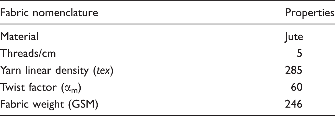
Jute fabric specifications.
Methods
Pretreatment of jute fabric
Prior to the formation process, the jute fabrics were impregnated with16 % NaOH solution at the temperature (22℃) for duration time (30 min), maintaining fiber weight to alkali volume ratio of 1:30. The fabrics were then washed thoroughly with distilled water for 60 min to remove chemical residues until the pH value of about 7 was obtained [35]. Finally, the fabric samples were squeezed and dried at room temperature. The chemical treatment of the jute fibers increases the percentage of cellulose by 30% and decreases the other constituents [34]. The percentage of NaOH and the time of treatment were chosen in order to get the maximum increase in the fabric crimp, avoiding the degumming of the jute fiber or significant reducing of the fabric strength [35,36]. The raw jute does not have the crimp in structure. The caustic treatment of the yarns results in length shrinkage. The alkali treatment removes a significant amount of the hemicellulose and small quantity of soluble lignin presented at the jute structure allowing a shrinkage of the fibers and resulting high bulk yarn. This means the increase of the yarn crimp [37].
Tensile test
Tensile test of fabric was performed by a universal testing machine; it has been carried out by preparing the sample according to ASTM D 5035 standard [38]. The statistical average is calculated from five samples.
Bursting test
The bursting strength test of the fabric was carried out at Constant-Rate-of-Traverse (CRT), Ball Burst Test, according to ASTM D 3787 standard [39], ball diameter 25.4 mm. The statistical average is calculated from five samples.
Experimental setup
The designed setup, shown in Figure 1, permits to test the formability of textile reinforcement at the different conditions. Cyclic loading with various regimes and cycle times was applied under hot air of temperature up to 140℃ which increases the fibers strength [35,36]. As illustrated in Figure 1, the tested fabric is placed between two plates of fabric holders. The upper half of the die is fixed to the upper plate fabric holder. In addition, both are fixed to the heating section to form the upper part of the set-up. This part can move downwards manually or by using a servo motor to move the upper part downwards in steps, according to the regime of forming cycle. After finalizing the formation processes of the 3D fabric shape, the upper half of the set-up will move upwards to its initial position. The lower part of the set-up consists of the lower half of the die which is fixed to the piston of single cylinder engine, its crankshaft is driven by variable speed motor to control the speed of pressuring cycle applied to the fabric during forming.
Set up for 3D fabric formation.
The rotation of the crankshaft will apply tension–tension cyclic stress on the fabric, as shown in Figure 2.
Stress variation during fabric formation.
The value of the stress σmax should be less than the breaking stress of the fabric in order to prevent fabric bursting, so σmax should be ≪bursting stress of the material.
The maximum stress value is obtained from the bursting-elongation curve, while Δσ is constant as the crank length is constant. After predetermined number of cycles, the fabric bagging will reduce the value of the stress during the reciprocation of the die. The movement of the fabric holder downwards by distance Δy will again increase the level of the stress up to σmax. This process will continue till the final formation of the designed shape. The value of the σmax was obtained from the bursting load-elongation curve of the fabric. In our case, maximum stress (σmax) is 30.56 N/cm2 and (σmin) is 10.19 N/cm2.
Manufacturing procedure of forming 3-D jute fabric
The 2-step fabrication method of the 3D fabric forming is suggested to be used with the application of a cyclic loading on the fabric sample in a hot air environment. The composite fabrication process was completed in two steps: The first step is bagging the 2D fabric to fit the die final shape through the application of cyclic load, followed by the hot press through pressing two halves of the mold. The second step is the infusion of the resin. Figure 3 illustrates the procedure of composite manufacturing sequence.
Manufacturing of jute fabric-reinforced composite.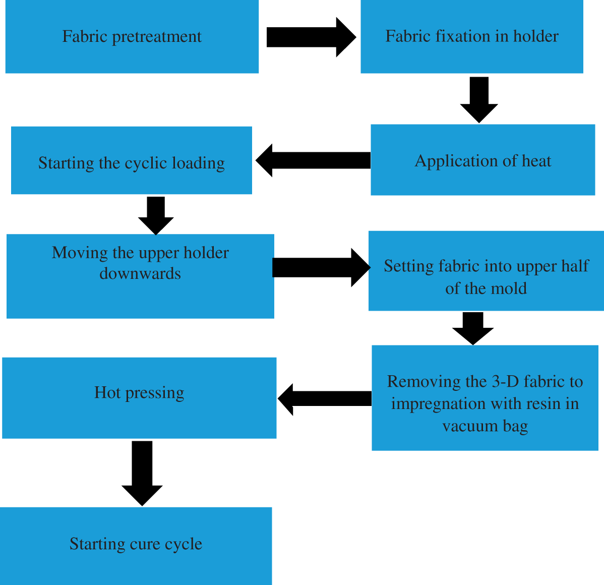
Fabric forming under cyclic loading
The sample sheet of fabric is gripped firmly around its circumference by a portable blank holder, having a die throat greater than the maximum diameter of the lower half of the die by 4 mm. Clamping was achieved by tightening the blank holder with the upper half of the mold inserted in the heater to attain the desired temperature of 140℃. Temperature controller was used to keep the temperature surrounding the fabric constant. The cycle of the 3D fabric formation is given in Figure 4. The fabric was subjected to cyclic loading for time intervals of ΔT, then the bottom die half moved downward for distance Δy. This cycle was repeated till the final height of the mold shape was reached. The process was performed at a constant temperature ToC, depending on the type of a material used. The die was kept at the constant temperature for a period of 30 min for annealing.
Regime for 3D fabric forming.
Obviously, the number of cycles during each step of formation, pressure rate, i.e. how much time it takes to reach upper limit, and clamping pressure, i.e. the pressure required to hold the two halves of mold during forming at the end of the hot press process, were chosen depending on the physical and mechanical properties of the fabric, fabric design, and type of fibers.
Results and discussions
Analysis of the fabric forming mechanism under cyclic loading
The mechanism that governs the effect of the cyclic loading on the textile structures is quite different than in the case of other types of materials [7]. The textile structures may be in the form of random, allied, in form of twisted structures (yarns), or woven structures. In all these structures, the friction forces are the main governing factors that hold the structure together. The mechanical properties of the textile structure will depend extensively on fiber properties, packing density of the structure, friction properties, and nature of loading.
The application of the cyclic loading on the fiber structure will lead to the reorientation of the fibers in the structure since they tend to get the position of the minimum energy level. Cyclic loading causes straightening of the crimped structure elements, hence the friction properties prevent the fibers to retain to their initial location after removing of the load, redistribution of the stress of the different elements of the structure, increase non-recovery elongation of the structure. At high values of a number of cyclic loading, failure of the structure due to loss of its integrity can occur [40,41]. In the case of fibrous structures of high packing density and tightness, the fibers are firmly fixed in position and the cyclic stress applied on the yarns will cause fatigue to the fibers after a very high number of cycles. Straightening and relocation of the fiber increase the yarn length [7]. In the case of fabrics, when the value of the maximum stress σmax is less than that at bursting stress, the effect of the cyclic loading will lead to the movement of the yarns under low strain, and therefore may achieve the reorientation of the fibers in the yarn and increase the yarn stiffness. The cyclic loading has a very destructive effect on a fabric only when a fabric is subjected to cyclic stress higher than the bursting stress that depends on the fabric type, design, and specifications. Otherwise, fabric bagging will attend [41]. The value of residual bagging depends on the yarn material, fabric design, as well as the yarn to yarn friction properties.
For basic investigation of the plunger motion, a unidimensional model is considered. When the fabric is pressed axially by a spherical plunger, the yarns will be constrained under radial force to the surface of the sphere.
For basic investigation of the plunger motion, the forces applied on the yarn, Figure 5, under the pressing of the plunger will be: Pressure force Fp, Packing force Pp at the tangent plane to the yarn body, Friction force Ff at the surface of the contact between yarn and sphere, Friction force Fc between the warp and weft yarn at the point of intersections, Bending moment Mb due to yarn stiffness, Tension force Ti [25].
Forces acting on the weft and warp yarns element under pressure of the spherical plunger.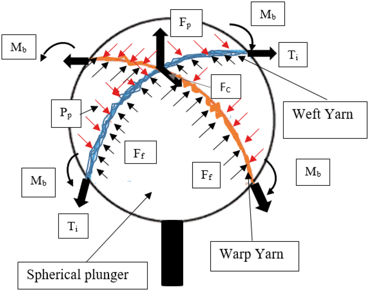
In the case of flexible weft and warp yarns and low value of friction between the yarns and sphere surface of the plunger, the main force acting on the yarns will be the sum of the force required to strain the yarns in the final form and the friction force between the two sets of the yarns at the point of the intersection. The warp yarn has a tendency to pull off the weft yarn at the point of the interlacement along its length as illustrated in Figure 6(a). Accordingly, the pulling force is determined by the yarn-to-yarn friction over and under the crossing areas in the fabric structure [42,43]. Subsequently, the value of the friction force between the warp and weft yarns depends on the magnitude of the forces on both sets of the yarns and is influenced by the value of tension force acting on the yarns. Therefore, the warp tension at the point of the interlacement with weft yarn will cause the weft yarn to bend and take an elliptical form as shown in Figure 6(b).
(a, b) Friction on the weft and warp yarns during forming.
The adhesive surface force Twarpi at one contact point [44] due to the pressure of the weft yarn on the warp P
warpi
will be added to the yarn strain force. The value of pressing force P
warpi
Strain of ith warp yarn Young’s Modulus of the warp yarn Coefficient of friction between the warp and weft yarns Angle of contact between warp and weft yarns at the intersection points Stress in the weft yarn at the intersection point.

A similar equation for the weft yarn can be concluded.
Equations (1) and (2) are used in the determination of the maximum value of the stress σmax.
Based on the above analysis, the configuration of the weft yarns on the surface of the sphere, Figure 7, confirms the equilibrium of the forces acting on each weft yarn, causing firstly de-crimping and extension of the pull-out warp yarn itself and displacements of the yarns that lay orthogonal to the pull-out direction, that is, the localized shear of the fabric. Secondly, the pull-out force is involved in overcoming the initial adhesion at the crossovers, that is, the static friction and thereafter the friction of split junctions of the weft and warp yarns, the kinetic friction [43]. The final form is, therefore, largely ruled by the frictional phenomenon at the crossover regions. The value of pulling force is proportional to crimp percentage, fabric density, and fabric weave structure. The strain on the yarns is variable and depends on their location on the surface of the sphere. The strain maximum value Weft yarn configuration on the sphere surface after forming.
Figure 8 illustrates deformation of the fabric under the movement of the spherical plunger. The bursting of the treated jute fabric starts with de-crimping of the fabric in both weft and warp directions under low values of bursting force, followed by straining the yarns (Figure 8). The yarns are continuously strained by the pushing of the bursting ball till failure.
Deformation of the jute fabric under the movement of the spherical plunger.
In order to derive a complete understanding of the mechanism for surface modification of different types of fabrics, woven and triaxial fabrics were subjected to the cyclic loading. For woven fabric, the warp and weft yarns are configured after being bagged by the spherical plunger, as shown in Figure 9.The value of residual bagging was found to be a function of the friction properties and the mechanical properties of weft and warp yarns [3].
Distribution of weft and warp yarns on the surface of bagged area plunged by spherical plunger (ply polyester continuous filament yarns) initial fabric after bagging.
In view of low coefficient of friction between the contact points of a set of yarns, such as Triaxial fabric [45,46], the yarns will move freely, widening the spaces between them as shown in Figure 10.
Distribution of the yarns in triaxial fabric on the surface of bagged area plunged by spherical plunger (polyester continuous filament yarns).
In the situation of a low value of frictional forces between the spherical plunger and yarns and low yarn stiffness, yarn’s geometry will be tilted more from its original plane (YZ) under packing force Pp, as it appears in Figure 10.
The shear stiffness and bending rigidity play a significant role in the suitability of the fabric to wrap the die shape without wrinkling. The higher the drape of a fabric, the better will be the formability.
Jute fabric forming under cyclic loading
The main objective of the processes of stretch forming and deep drawing is to have a high value of the relative residual bagging area before the infusion of the thermoplastic resin for manufacturing of the textile composite. This area should be compensated through the extension of the fabric during the formation process without overstressing of the yarns [25]. Since the jute fabric has low breaking extension and crimp, it should be pretreated before forming to increase both these values through the alkali treatment [31,35].
Effect of NaOH pretreatment on the jute fabric properties
Another concentration of the present study was to increase jute fabric breaking elongation. The treatment of the jute fibers, yarns, and fabrics has been explored by several investigators [1,31–34]. The effect of the NaOH treatment on the jute fabric can be briefly summarized in the following: contraction of the fabric in both weft and warp directions resulted in increase of the crimp of the weft and warp yarns, decrease of fabric Young’s modulus, decrease of fabric stiffness, and increase of the weight per unit area of the fabric [35,36,47,48]. All the above factors are affected by the concentration of the NaOH, time of treatment, and the temperature. For fabric formation, the main properties that impact the process of curving the fabric under pressure applied by the plunger are fiber and yarn crimp, the initial elongation of the fabric, fabric Young’s modulus, and fabric bending stiffness. The increase of fabric crimp is associated with the decrease of fiber and fabric Young’s modulus [35] and turned into a reduction of fabric bending stiffness. The experimental measurements were compared, as shown in Figure 11(a) to (d).
(a–d) Load-elongation curve of treated and untreated jute fabric in weft and warp directions. (a) Untreated warp wise, (b) treated warp wise, (c) Untreated weft wise, (d) treated weft wise.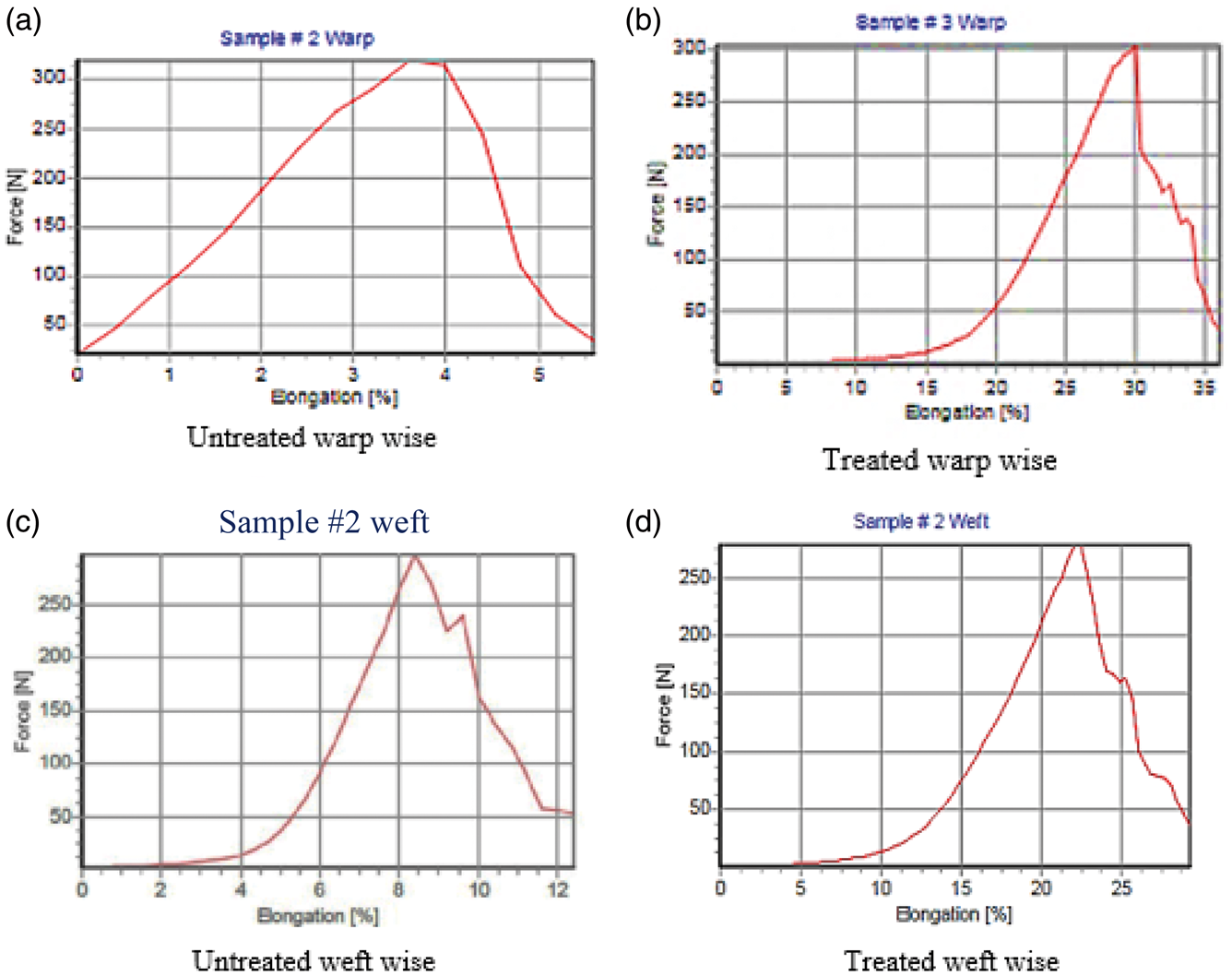
Figure 11(a) to (d) shows the load-elongation curve of the untreated and treated jute fabrics in both weft and warp directions. The unequal crimp of the weft and warp yarns results in the difference of the initial elongation of the load-elongation curve of untreated and treated jute fabrics. The crimp of the warp yarns was found to be less than the weft yarn; consequently, this reflected on the load-elongation curve. The initial elongation is due to the de-crimping of the weft or the warp yarns under the applied axial load and followed by extending the yarns.
The presence of crimp delays the linear relationship between load and elongation in the fabric, and the extent of the delay is related to the magnitude of crimp ratio, as shown in Figure 11(a) and (c). Treating the jute fabric with NaOH leads to increase in the percentage of the crimp and so the breaking elongation as indicated in Figure 11(b) and (d).
Properties of jute fabric.

CV value.
The present investigations were conducted on performed bursting test on the fabric previously to its use to assure that the bursting extension is lower than the maximum height of the targeted shape. Figure 12 shows the bursting load-elongation curve of the treated and untreated jute fabrics. This indicates that the fabric straightening allows a deformation of the fabric up to 8 mm at low loading of the warp and weft yarns, while the untreated fabric will completely fail after ball displacement of 7 mm.
Burst-load elongation curve of the treated and untreated jute fabric.
Continued pushing of the ball through the treated jute fabric initiates the de-crimping of the fabric in both weft and warp directions under the low magnitude of bursting force, followed by bursting of the fabric with nearly straightened yarns, Figure 12. The mechanism of failure will be similar to the untreated fabric and almost linear. The increase in the bursting load of treated fabric may be due to the better distribution of the biaxial forces on the warp and weft yarns.
Forming jute fabric under cyclic loading
The application of the cyclic loading during forming facilitates the sliding of the interlaced yarns and dropping the yarn to yarn friction. When the jute fabric was pretreated with NaOH, the structures of the fibers, yarns, and fabrics are altered because of the change in their physical and mechanical properties, especially the breaking elongation. Therefore, this gives the possibility to enhance the mechanism for the formation of the residual bagging. Predicting not to deteriorate the fabric mechanical properties for combined stretch forming, the yarn final stretching should not be higher than the final yarn elongation due to the de-crimping and yarn stretch under cyclic loading during formation ɛtotal [25].
The hot pressing under cycle loading regime, which is described in Figure 4, was used to form 3D jute reinforcement shape with the pretreated jute fabric of specifications given in Table 1. Figure 13 gives the dimensions of the target die form. The number of cycles for each step of the formation in time Δt was 1 min at the rate of 1000 cycle/min, while the value of the steps Δh was 3.5 mm and the processing temperature was 140℃. Figure 14(a) to (c) demonstrates the final form of the fabric preform that illustrates the absence of the wrinkles. Figure 14(c) illustrates the distribution of jute woven fabric weft yarns in relaxed preform after being bagged.
Die dimensions. (a–c) 3D jute fabric bagging in relaxed preform.
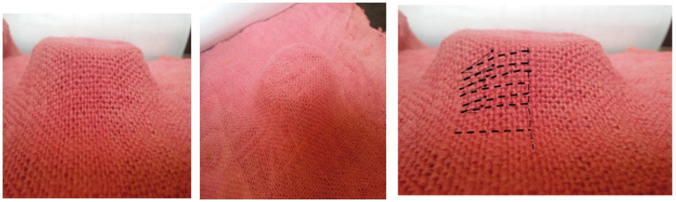
The final form of the jute matrix after polypropylene polymer infusing and molding process is illustrated in Figure 15(a) to (c). Several other shapes were formed using the above-described technique for textile composite formation.
Jute fabric-reinforced polymer composite formation. (a) After hot press, (b) after polymer infusion, (c) final shape of the jute-reinforced polymer composite.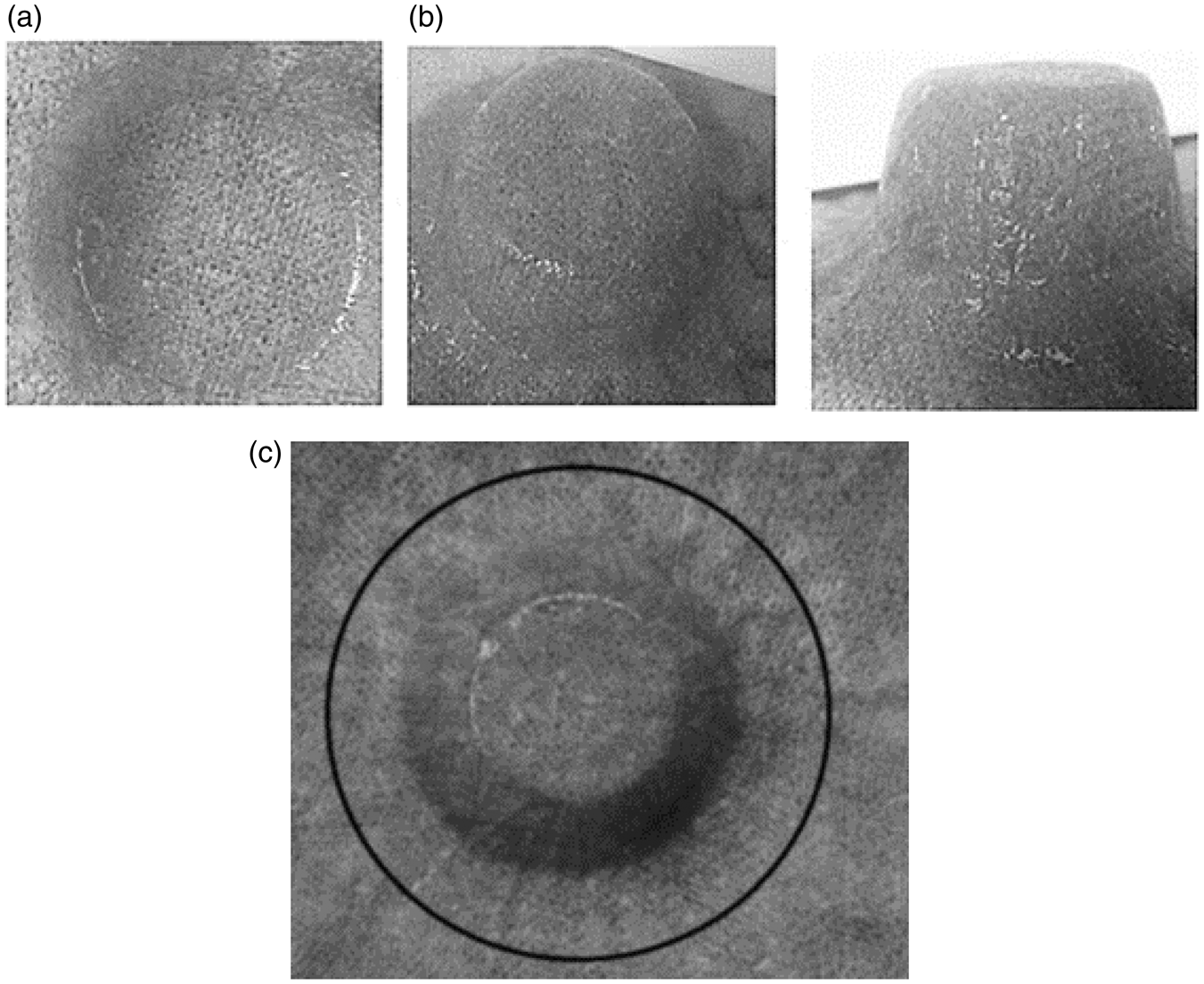
The same technique can be applied to various types of fabrics, for instance, knitted fabrics, which can permit high values of the initial extension, leading to larger sizes to be formed. The residual bagging of the fabric depends on the frictional and mechanical properties as well as material thermal properties [7].
Conclusion
In this paper, the developed methodology based on the dynamic bagging allows forming the 3D fabric reinforcement preform from 2D fabric without wrinkles.
The hot press fabric forming is proposed to be used with the application of a variable cyclic loading under hot air. The composite fabrication process was completed in two steps: bagging the 2D fabric to fit the 3D die and hot-pressing into the final shape, followed by the infusion of the resin. This method permits forming complicated neat 3D profiles. Visualizing not to deteriorate the fabric mechanical properties for combined stretch forming, the weft or warp yarn final stretching should not be higher than the final yarn elongation due to de-crimping and yarn stretch under cyclic loading during formation cycle.
Proof-of-concept experiments have been performed for jute fabric after pretreatment by 16% NaOH to increase fabric crimp and elongation to reach the required strain for the deep forming. The value of applied fabric straining under cyclic loading can be obtained from the bursting-elongation curve of the fabric. This technique indicated promising potential.
Footnotes
Declaration of Conflicting Interests
The author(s) declared no potential conflicts of interest with respect to the research, authorship, and/or publication of this article.
Funding
The author(s) received no financial support for the research, authorship, and/or publication of this article.