
Abstract
Interest in natural fiber–reinforced composites (NFRCs) is increasing rapidly thanks to their numerous advantages such as low cost, biodegradability, eco-friendly nature, relatively good mechanical properties, and a growing emphasis on the environmental and sustainability aspects of engineering materials. However, large-scale use of NFRCs is still considered as challenging due to the difficulties in manufacturing, limited knowledge of its machinability and appropriate parameter settings, and being prone to machining-induced defects. This article presents a comprehensive review on various aspects of NFRCs, with a focus on the manufacturing and machinability. It covers some recent works related to NFRCs, including the manufacturing processes and parameters, characterization of mechanical properties, applications, and machinability and machining process monitoring, many for the first time. The main challenges associated with machining of NFRCs and the induced damages are outlined, with special attention paid to the effect of physical properties of the fibers and manufacturing process on the machinability, along with the essential machining parameters that affect the quality of the machined surface. The research perspectives and the current application status are also discussed. The article is intended to help readers attain a fundamental understanding of key technologies and the state of the arts in this research area.
Introduction
In recent years, the ever-increasing awareness of nonrenewable resources becoming limited and a predictable reliance on renewable resources has brought much attention to the development of biodegradable and environmentally sustainable composite materials. 1 Environmental legislation connected with industrial and consumer demands around the world is putting more pressure on manufacturers and scientists to explore novel environmental friendly and sustainable materials to replace existing synthetic fibers and lessen the dependence on petroleum-based products. In this context, overconsumption of petroleum-based plastics causes a severe depletion of natural resources and landfill capacities. 2,3 There has been a growing trend to develop and use bio-composite materials in many engineering applications with a wide variety of properties, especially with those employing natural fibers as fillers or reinforcers.
Natural fiber–reinforced composites (NFRCs) are increasingly being used in many engineering applications with an extremely wide variety of properties. Natural fibers are classified based on their origins, whether they are derived from plants, animals, or minerals. 4 Plant fibers include leaf fibers (pineapple, sisal, and abaca), core fibers (hemp, jute, and kenaf), grass and reed fibers (wheat, corn, and rice), seed fibers (cotton, kapok, and coir), bast fibers (flax, jute, hemp, ramie, and kenaf), and all other types (wood and roots). Polymer matrices can be divided into two types; one is synthetic petrochemical-based called synthetic matrix (polyester, polypropylene (PP), polyethylene (PE), epoxy, etc.) and the other is natural or bio-based called biodegradable matrix. 3
Comparing with synthetic fiber composites, natural fiber–based composites possess some superior properties such as low cost, lightweight, biodegradability, high thermal and acoustic insulation, and high specific strength and stiffness. 5 In fact, synthetic fiber–based composites have got some serious drawbacks such as high cost, high energy consumption in machining and manufacturing processes, poor recycling and non-renewability properties, CO2 emissions and health hazards when breathed in. 6 These shortcomings have caused natural fiber composites to emerge as a promising alternative to synthetic fiber composites. Unlike synthetic fibers, natural fibers can be incinerated at the end of useful life with enhanced energy recovery and no net addition to CO2 emissions, which leads to positive carbon credits and lower global warming effect.
On the other hand, there are also some main disadvantages that restrict the use of natural fibers and recyclable polymers for emerging new composites, such as low resistance to moisture absorption, thermal degradations and weathering effect of fiber and matrix, lower durability, poor interfacial adhesion that leads to debonding, and poor wettability of resin impregnated into spaces between fibrils and breakage of fibers during mixing of the manufacturing processes. 4 Consequently, through suitable material selection and design, a proper balance between production cost of composite and their overall properties can be simply achieved.
Natural fiber composites have been embraced by car manufacturers and suppliers to replace a large segment of the synthetic and mineral fillers in numerous automotive interior and exterior parts. As a result of a widening range of NFRCs usage in several industrial applications, the machining of these materials needs to be perceived meticulously with regard to their different behavior than machining of conventional metallic materials.
Machining of NFRC is a rather intricate task due to the mechanically anisotropic and inhomogeneous structure, high abrasiveness, and hard reinforced fibers. Several noteworthy problems can be found in the machining processes, especially in drilling, including delamination, fiber peel-up, fiber pullout, spalling, hole shrinkage, fuzzing, and thermal degradation. 7 The undesirable damages induced by the drilling process result in lowering strength against fatigue, which can be extremely detrimental to the long-term performance of composites. Hence, more attention should be given to the selection of machining parameters and cutting tools as well as types of fiber used as reinforcement or filler in the composites and their mechanical and thermal properties. It should be taken into account that the machinability of a composite considerably depends on the mechanical properties and relative content of the reinforcement and the matrix material, which rely on many parameters such as fiber orientation, surface characteristics of the fiber, volume fraction, physical and mechanical properties of the fiber, and the structure of the composite. These parameters have a significant impact on the machinability of fiber-reinforced composites (FRCs) as it has been reported over the past decade. 6,8,9 Therefore, investigating the effects of each individual parameter on the mechanical properties of such materials and identifying their roles in cutting mechanism are highly imperative. By proper selection of machining parameters such as feed rate, cutting speed, drill type, drill diameter, and manufacturing parameters, such as manufacturing method, fiber volume fraction and fiber orientation, desirable quality to meet dimensional and assembly requirements in the machined composites can be effectively achieved.
There are a number of review articles describing different aspects of machining of composite laminates 6,10 –12 ; however, a comprehensive review paper on both manufacturing methods and machinability of these materials is still not available. The present article deals with the review of recent research and developments related to NFRC, such as characterization of mechanical properties, applications, manufacturing processes and parameters, and machinability and machining process monitoring, in a critical way, many for the first time. The review also considers the essential factors affecting the quality of drilled holes and discusses main challenges in machining of natural fiber composites in addition to providing information about online monitoring and controlling the machining process.
Characteristics and applications of NFRC
Natural fibers
Natural fibers are a type of renewable sources and a new generation of reinforcements to replace petroleum-based materials and man-made fibers. Natural fibers are subdivided on the basis of their origins, whether coming from plants, animals, or minerals. 13 The types and origins along with their annual production levels of the most important natural fibers are presented in Table 1.
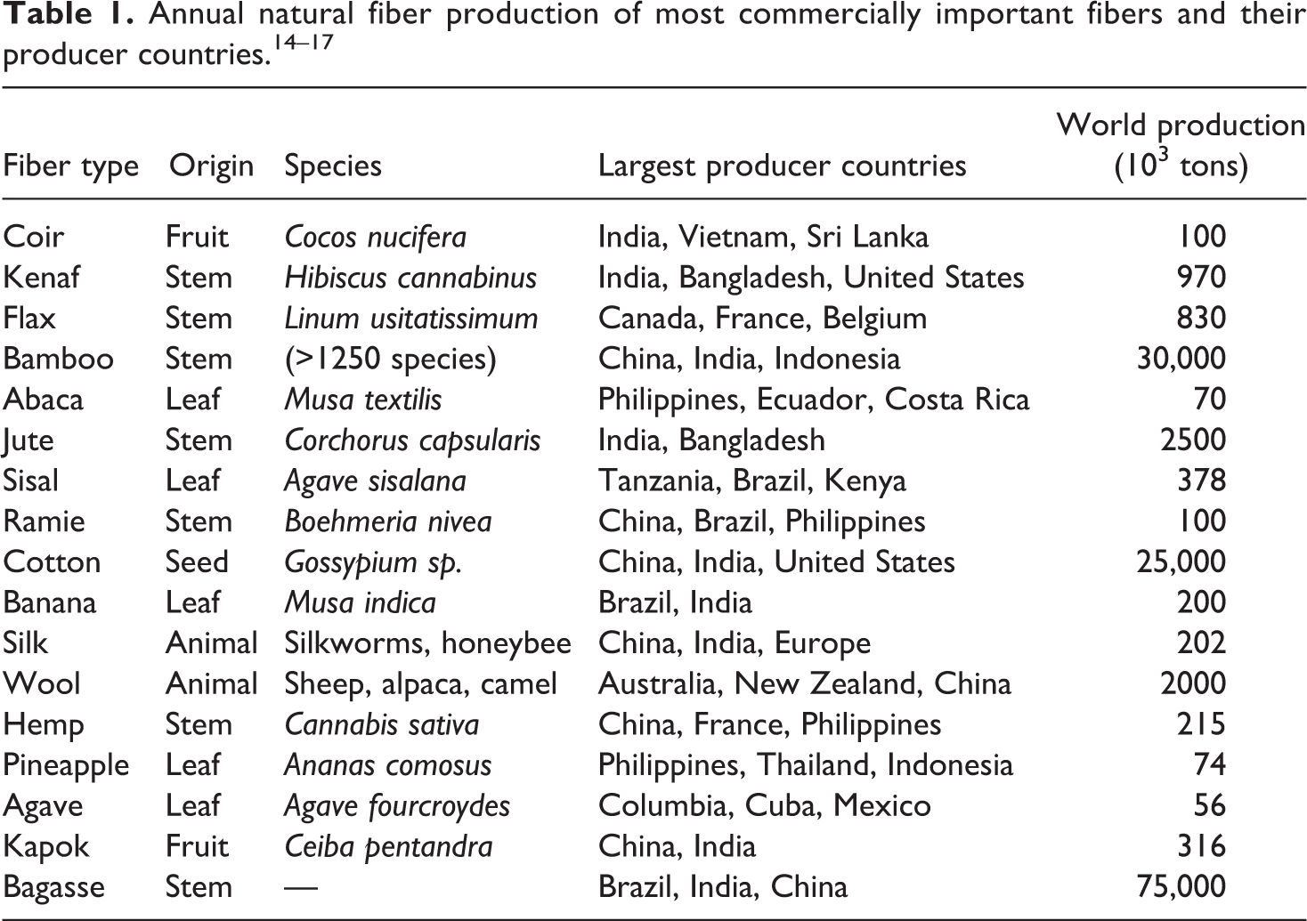
Figure 1 presents a summary of the different classifications of the most common natural fibers and matrices in detail. Plant fibers are mainly made of cellulose as is the case with bamboo, cotton, and coir, while animal fibers are generally composed of proteins such as keratin and collagen. Flax, kenaf, and hemp fibers are viewed as the most common and promising sustainable fibers for composites applications because of their abundant availability along with their superior mechanical properties, particularly high tensile properties, compared to those of other types of bast fibers.
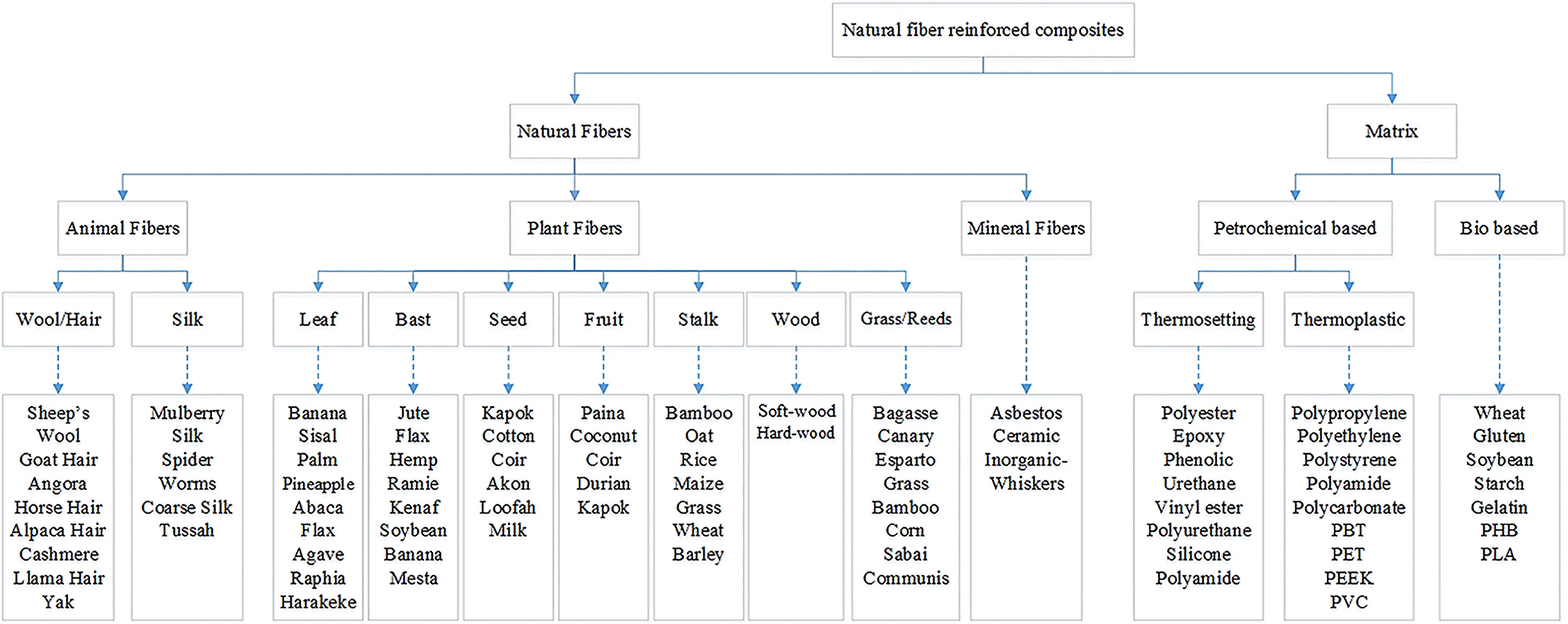
Classification of natural fibers and matrix used in NFRCs.
The cell structures of natural fibers are intricate layered structures, consisting of a hollow tube, which has four different layers, each with a distinctive thickness and chemical composition. The cell wall of fibers contains one thin primary wall and three secondary cell walls and the thick middle layer called lumen. The schematic structural constitution of a natural fiber cell is illustrated in Figure 2, where a series of cellular microfibrils helically wound along the middle hollow fiber axis is shown. 18 The age of the plant, species, climate, harvesting time, and fiber processing procedures would significantly affect the structure of fibers as well as their physical and chemical composition, which are the most significant factors in determining the overall properties of the fibers. It is believed that microfibrillar angle determines the fiber stiffness. Accordingly, fibers with a spiral orientated microfibrils are more ductile than fibers with a parallel orientation, which are more rigid and inflexible.
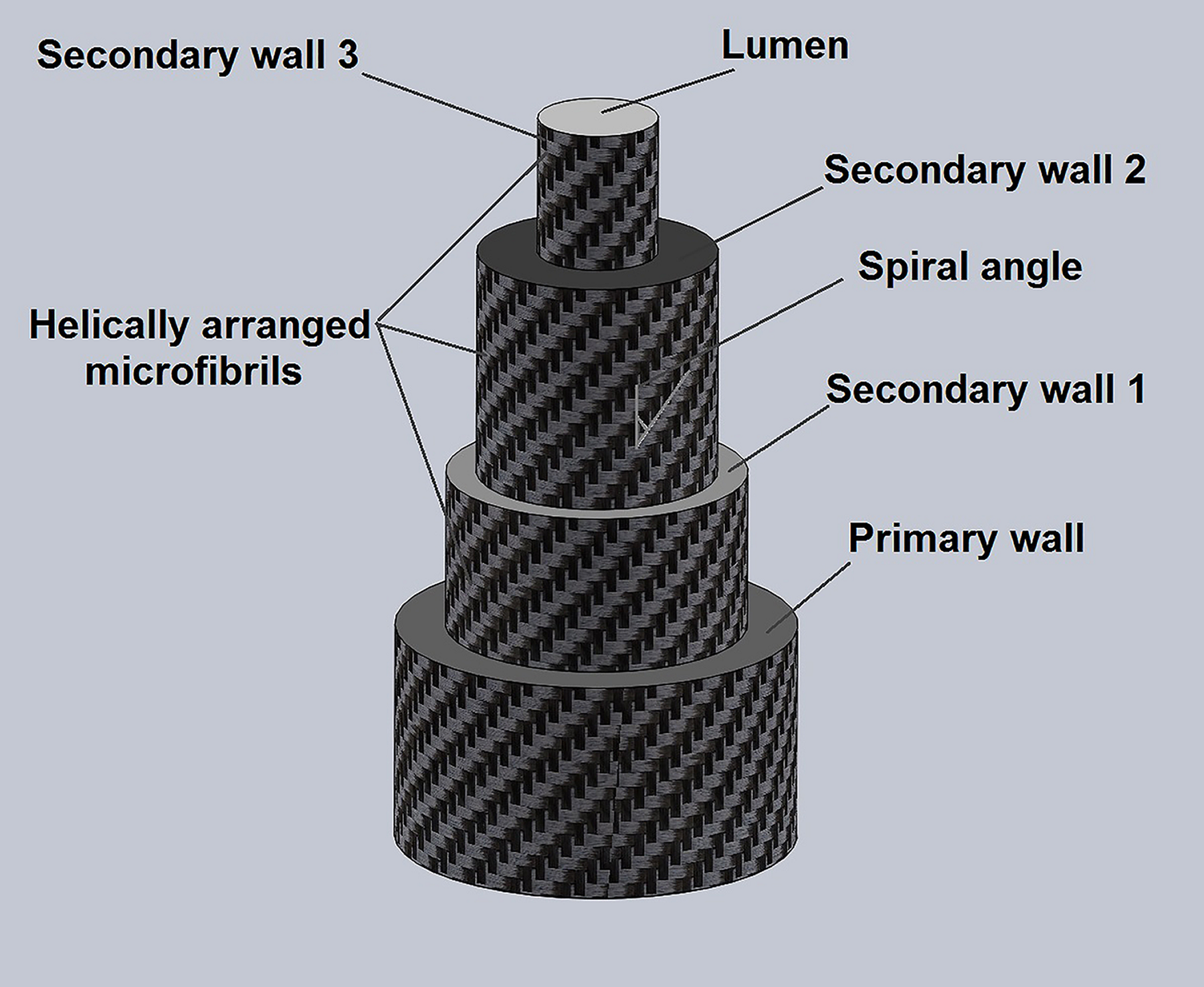
Structure of a natural fiber. 3
The mechanical properties of a single fiber are determined with its physical state and chemical composition of the cell walls such as crystallite content, shape, orientation, size, thickness of cell walls, and finally defects like lumen. The mechanical properties of natural and some synthetic fibers are summarized in Table 2.
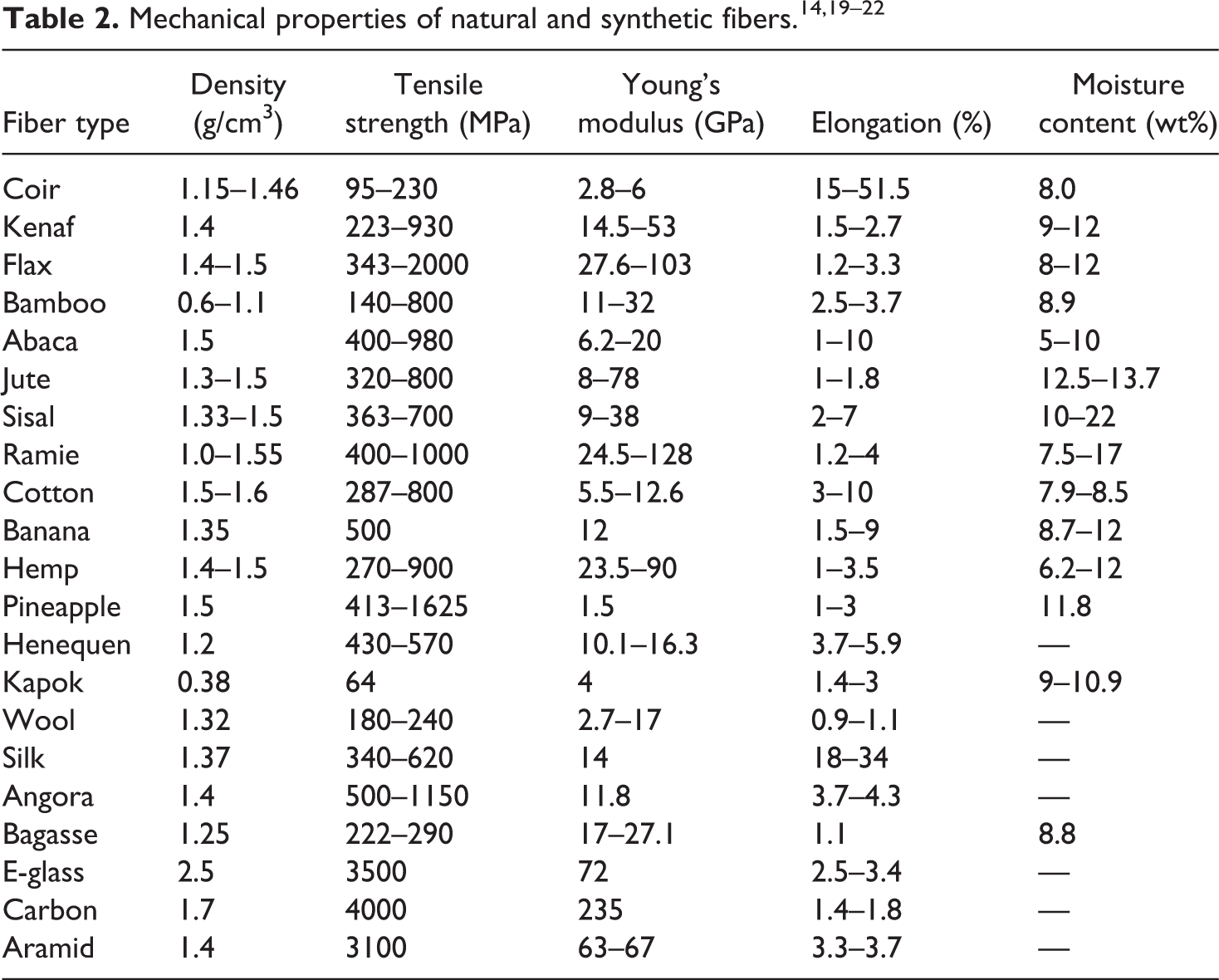
Natural fibers suffer from natural variability in structural properties as can be seen in the value ranges presented in Table 2. This variability of properties is caused by several factors, some are induced by seed density, fiber maturity, fiber age, soil quality, fiber extraction technique, fiber source and location on the plant, harvest timing, climate and some are related to the procedures of testing and characterization. 18,19 For engineering applications, in many industries, this variability within the mechanical properties of natural fibers leads to major difficulties toward designing reliable components as the parts have to be accurate, secure and their failure must be precisely predicted.
Natural fiber–reinforced composites
A FRC is a material constituting a matrix together with strong reinforcing fibers. The selection criteria of the matrices are limited by end use requirements of composites and the temperature at which fibers degrade. Most fibers (natural or synthetic) used as a filler in FRCs are thermally unstable above 200°C, thus the processing temperature is limited, although in some conditions it is likely for them to be used at higher temperature for short periods.
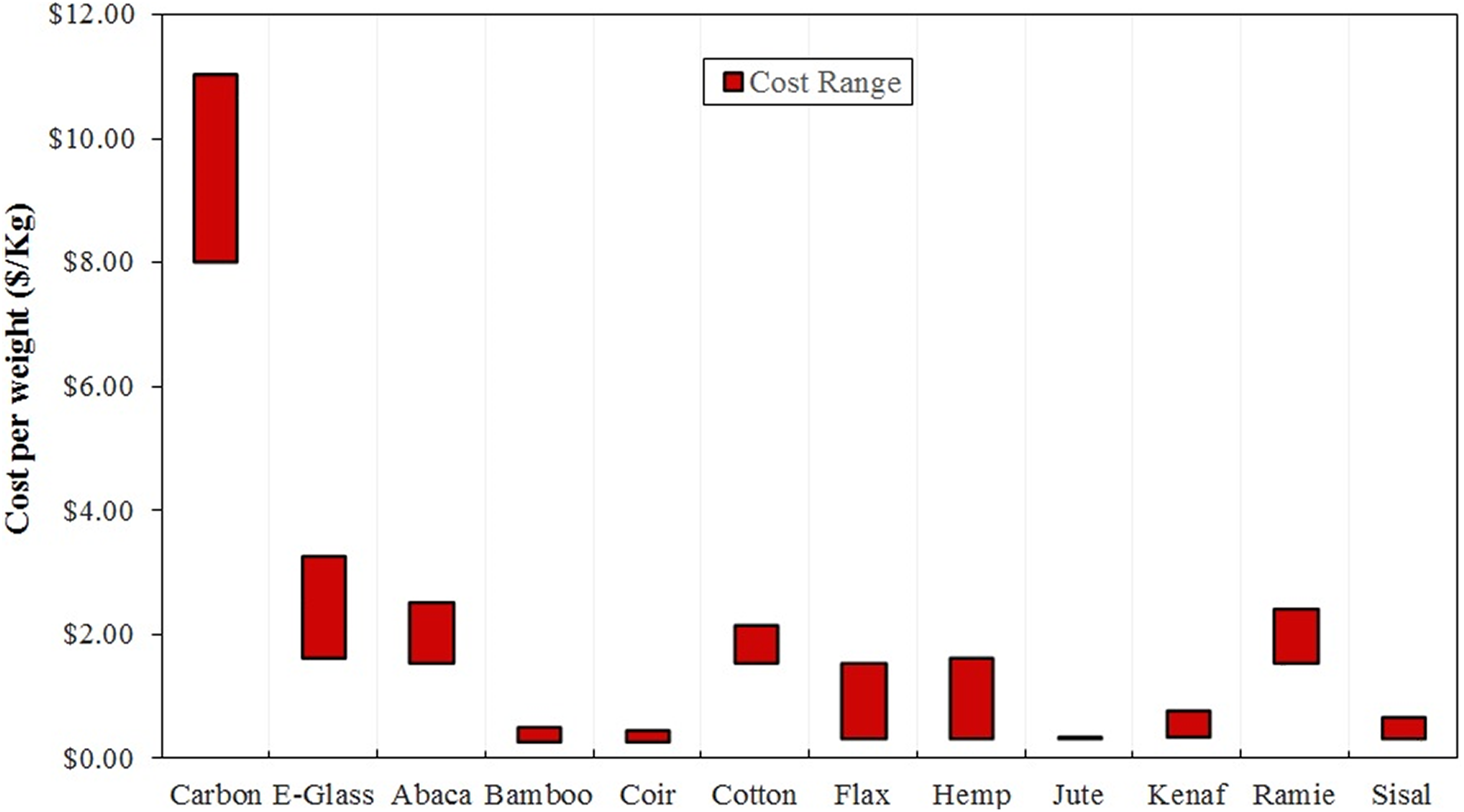
A cursory comparison has been made between natural fibers and the glass and carbon fibers, in specific Young’s modulus and cost per weight. According to Table 2, the specific Young’s modulus of ramie is the second largest one after carbon fiber and it is closely followed by flax fiber. It is observed that the specific Young’s modulus of natural fibers like ramie and flax is greater than that of E-glass. A comparison in cost per weight of the fibers, shown in Figure 3, illustrates that the unit price of most natural fibers is also by far lower than that of glass and carbon fibers. Hence, taking the mechanical performance, cost, and environmental consequences into account, among various fiber composites, NFRC using flax, hemp, and jute fibers can be considered as the suitable potential choices to be used as an alternative to glass and carbon fiber composites for numerous applications.
Fiber selection
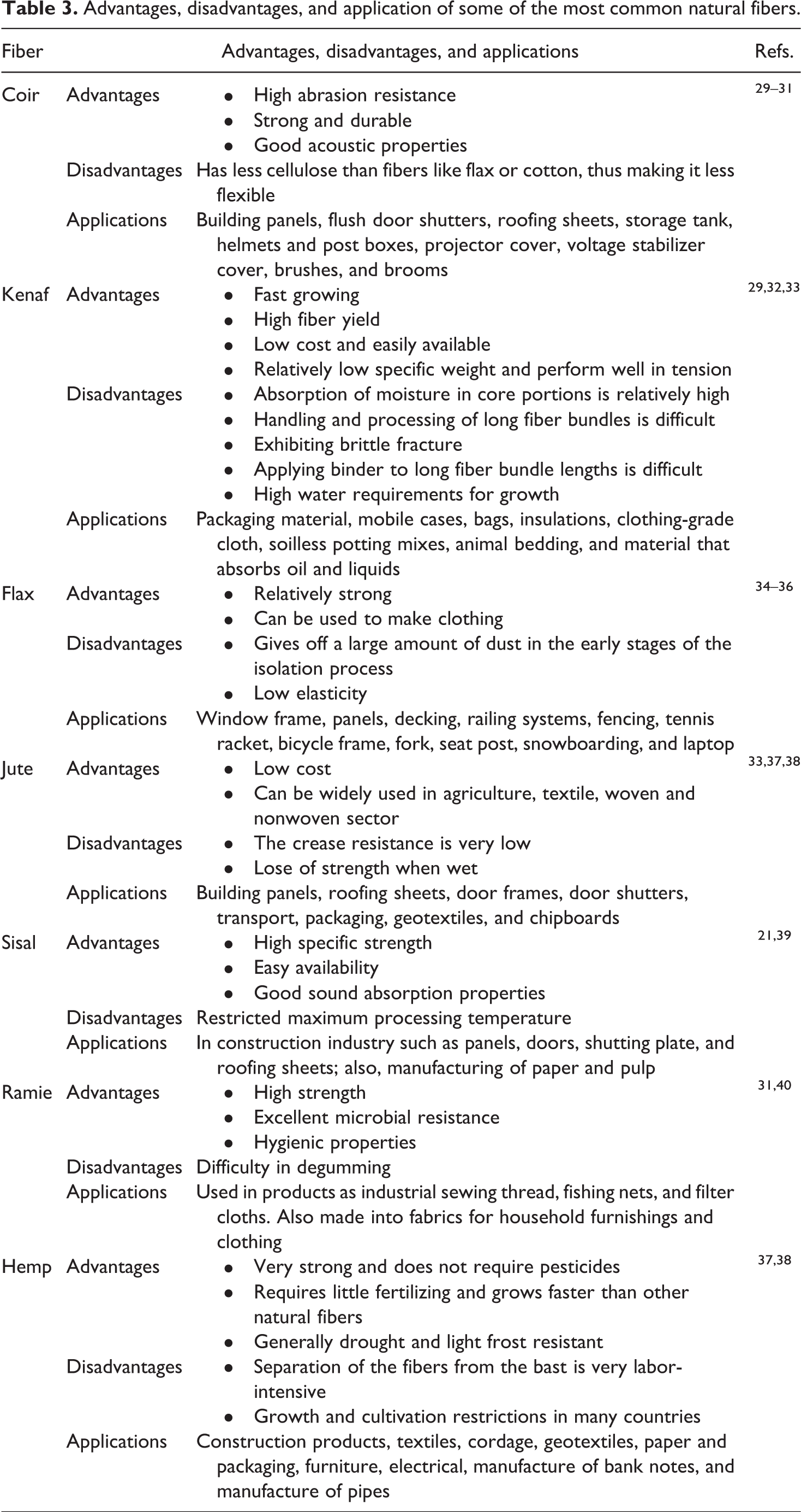
The fiber types or specification differences that seem imperceptible can result in serious functional differences that can directly affect the material performance and the cost. A number of studies have been conducted on the physical properties of fibers including fiber type, fiber size, aspect ratio (ratio between the length and diameter), porosity, fiber quality, moisture absorption, and the way fibers break through compounding with the matrix that considerably influence the final properties of natural fiber composites. 24 –28 Table 3 presents a list of some notable advantages and disadvantages of several commercially available natural fibers used as reinforcement. When it comes to the properties and application of the natural fibers, it is important to state that difference occurs when choosing one type of fiber over another. The performance of the composite depends on many factors such as structure, mechanical properties, physical properties, and microfibrillar spiral angle. Based on their advantages and disadvantages, NFRCs containing fibers such as flax, jute, hemp, and kenaf have been well received in many industries such as packaging, automobile, sport, construction, and electronic industries.
Advantages, disadvantages, and application of some of the most common natural fibers.
The mechanical and thermal properties of the fibers should also be considered in selecting fibers. The salient mechanical properties of the composites such as Young’s modulus, tensile strength, and stiffness are practically determined by the mechanical characteristics of the fibers. Therefore, relevant selection criteria for the choice of suitable reinforcing fibers for a FRC with a polymer matrix briefly include: thermal/physical/mechanical properties and relevance to end application, elongation at failure, sizing and surface treatments for matrix and fibers adhesion and wetting, dynamic behavior, price and processing costs, and availability, lead time, and stable supply source.
In addition, there are some further considerations that include economy, experience, and safety considerations that factor into the selection of fiber for composite material.
Matrix selection
The matrix is a substance that binds the reinforcing fibers together, gives the composite component its shape, and determines its surface quality. The matrix properties determine the composite resistance to most of the degradative processes such as delamination, crack propagation, water absorption, impact damage, thermal creep, and chemical attack that eventually lead to failure of the structure. Furthermore, the position and orientation of the fibers in composites are maintained by the matrix so that they carry the intentional loads, distribute the loads more or less evenly among the fibers, which provide crack propagation resistance due to the plastic flow at cracked tips. 41 Matrices for composites may be a polymer, metal, ceramic, or in some cases carbon. Polymer matrices are commonly used in commercial and high performance applications, while ceramic and metal matrices are usually applied in high-temperature environments, such as motor engines.
The matrix phase of most commercially produced composites is polymer matrix, which can be classified into two different types regarding their degree of reticulation, namely thermoplastic polymers and thermosetting polymers. Matrix selection highly depends on the composite end use requirement as matrix generally defines the overall service temperature of the composite and also determines its environmental characteristics. 42
Thermoset resin is a polymer in a liquid form that changes irretrievably into an infusible and insoluble material by curing. 43 The recycling process of thermosetting composites is very difficult as thermoset resin is nonrecyclable by itself. Thermoset resins are brittle at room temperature and have low fracture toughness and poor elasticity or elongation once hardened. They also offer high thermal stability, good rigidity, resistance to solvents and corrosives, resistance to creep, chemical resistance, and high dimensional stability. The most commonly used thermosetting resins in composites manufacturing are polyester, epoxy, vinyl ester, polyurethane, silicone, polyamide, and polyamide-imide.
Thermoplastic polymer resins are extremely common and usually are cheaper for fabrication compared with thermosets or elastomers. Thermoplastic composites present two major advantages. Firstly, many thermoplastic resins are characterized by high impact strength and toughness compared to thermoset resins. Another major benefit of thermoplastic composites is their ability to be easily recycled and reformed, which is extremely favored in current commercial market. However, it should be noted that impregnating reinforcing fibers in thermoplastic resins is much more difficult as resins are naturally in a solid state. Typical examples of thermoplastic resins include acrylonitrile butadiene styrene, polyvinyl chloride, PP, PE, polystyrene, polyamide (nylon), polycarbonate, thermoplastic polyester (e.g. poly(butylene terephthalate) (PBT), poly(ethylene terephthalate) (PET)), poly(ether ether ketone) (PEEK), and so on. 44
The partial replacement of petroleum-based plastics by novel bio-derived materials from natural renewable resources has significantly attracted the interest of many researchers and industries. Of these, polylactic acid (PLA) is one of the most promising biobased polymers which has replaced many commodity plastics due to its biodegradability and substantial mechanical properties. PLA has shown to present higher mechanical strength and stiffness with reinforcing natural fibers when compared to other polymers such as PP and PE. 45
Volume fraction
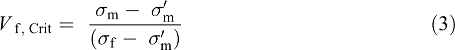
Fiber volume fraction (Vf) is the concentration percentage of fiber volume in the entire volume of a FRC material when impregnated within the matrix. Vf plays a significant role in determining the physical and mechanical properties of composites. For composites consisting of brittle reinforcing fibers in a ductile polymer matrix, NFRCs in particular, based on composites theory, there should be a critical volume fraction (VCrit) below which the strength of a composite will be lower than that of a matrix. 20 The strength–fiber content relationship is presented in Figure 4. As can be seen, there are two different possible failure regimes depending on whether the Vf is exceeding the minimum value (Vmin) or not. If a composite with very few fibers below the minimum volume fraction (Vf < Vf, min) is stressed, fibers failure does not result in composite failure as the polymer matrix can cope with the applied load but the broken fibers, which now carry no load, can merely act as an array of aligned holes within the matrix. This means that reinforcing fibers have weakened the composite rather than strengthened it, and the composite strength is even lower than that of the matrix alone.
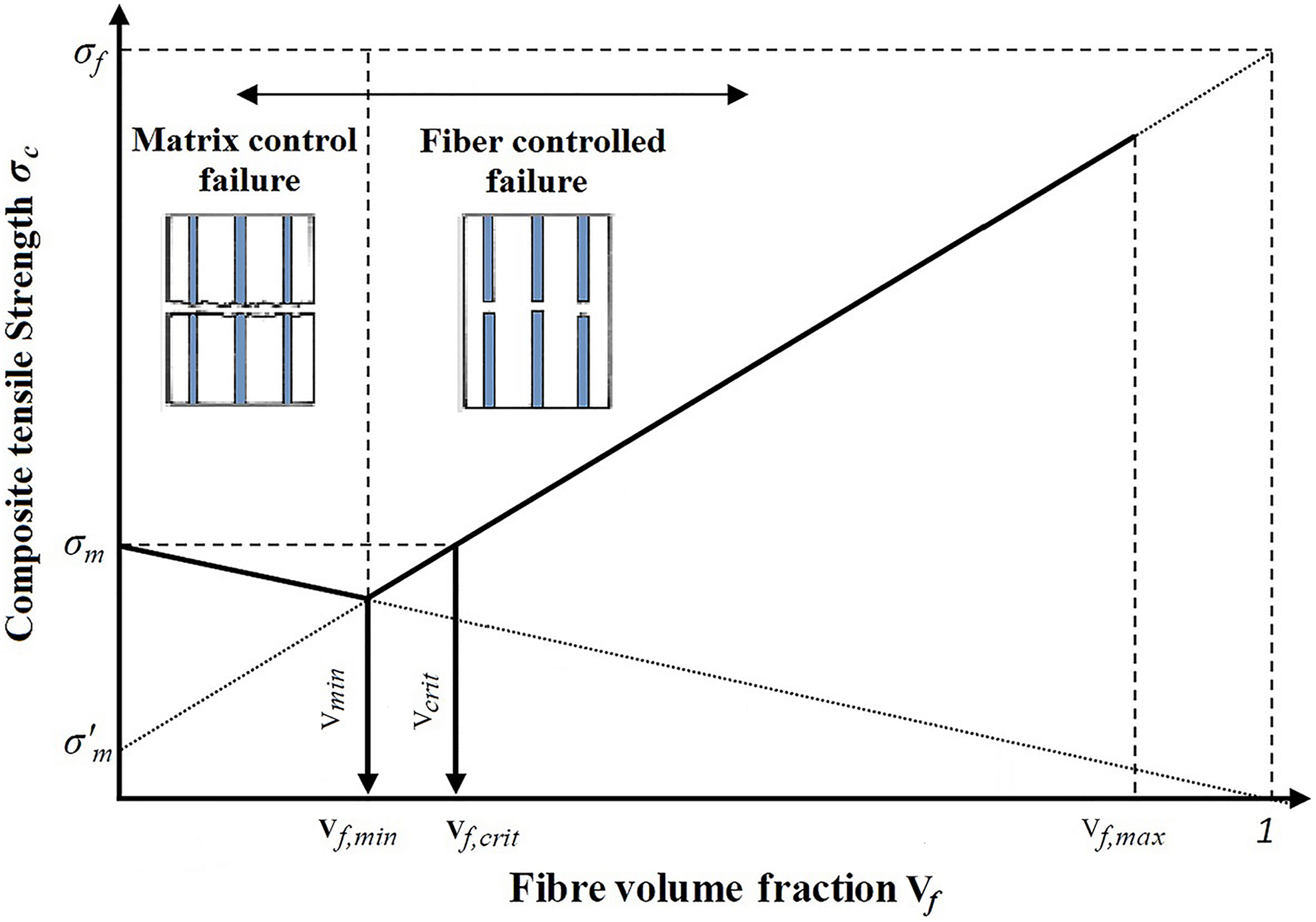
Relationships between composite tensile strength and fiber volume fraction.
On the other hand, if the content of fiber exceeds the VCrit (Vf > Vf, Crit), fibers failure results in composite failure, since the polymer matrix is not able to carry an additional load transmitted to the matrix from the fibers. 46 Therefore, the reinforcing role of the fibers is only happening once the Vf surpasses the Vf, Crit as it is well described diagrammatically by Figure 4 and mathematically by the below equations


where σc is the composite strength, σm is the matrix strength,
It has been reported that the mechanical properties of composites improve with certain increases in Vf. 11,48 However, above a certain level, composite mechanical properties deteriorate drastically due to fiber clotting, increase in porosity, or fiber–fiber interaction. 25,49 Therefore, the proper selection of a fiber volume is of paramount importance for strengthening the composites.
Fiber orientation
Fiber orientation is a key parameter that also plays a key role in controlling the mechanical properties of composites. Proper fiber orientation and dispersion is required to achieve a superior material performance. Generally, optimal strength and stiffness can be achieved by aligning the fibers parallel to the loading direction. 50 It should be noted that when the load is applied perpendicular to the fibers, composites can perform very poorly. However, getting alignment for natural fibers is more challenging than for continuous synthetic fibers. Another method to fabricate a more isotropic composite is to use multiple plies of continuous fibers with the different direction of fibers in each ply. Fibers can vary by 30°, 45°, or 90° angle to adapt for the direction of the applied loads. It has been reported that the microhardness of composites, as well as other mechanical properties such as tensile strength, flexural strength, and impact strength, is also affected by fibers orientation. 51 It was found that with increasing orientation angle of an alfa natural fiber composite from 0° to 90°, its mechanical properties decrease notably. This can be attributed to the fact that longitudinally oriented fibers behave like obstacles avoiding the stress distribution in the matrix, which leads to a higher stress concentration and poor mechanical properties. 48 In regard to the degree of fiber orientation effect on the mechanical properties of NFRCs, the tensile strength and Young’s modulus of hemp/PLA nonwoven composites with fiber orientation angles of 45° and 90° were found to have 48% and 30% of the strength and 53% and 42% of the Young’s modulus of 0° orientation, respectively. 52 In another study on sisal-reinforced epoxy composites, the maximum values of mechanical properties such as tensile strength and flexural strength were obtained in the 90° orientation (unidirectional) compared to 0°/90° and ±45° orientations. 53
Applications
NFRCs are now finding extensive and rapid usage in numerous fields from household articles to industry and military applications. The applications include transportation (automobiles, railway coaches, aerospace), marine, sporting products, construction industries, electronic industries, packaging, and so forth. 17 Using natural fiber in the automotive industry was initiated in the 1930s when for the very first time, Henry Ford advised the usage of natural materials, such as hemp, in producing reinforced soy resin composites for manufacturing body panels. 54 Natural fibers such as flax, sisal, or kenaf have been embraced by car manufacturers and suppliers in the world to reinforce plastic body panels and car interior trim parts such as seat backs, window panels, door panels, packaging trays, hat shelves, and dashboards. European automobile manufacturers (BMW, Audi Group, Ford, Rieter Automotive, Volkswagen, DaimlerChrysler, and Mercedes), for instance, use cellulose fiber composites in many automobile parts, such as using coconut fibers rubber latex composites for the seats of the Mercedes-Benz A-Class model and using flax–sisal fiber mat–reinforced epoxy door panels for Mercedes-Benz E-Class model. 31
Toyota has recently unveiled a particularly unique concept car at Milan Design Week, built entirely from Japanese wood, cedar, and birch, with no nails or screws to hold it together. The Toyota Setsuna powered by an electric motor is built to last a century of use, making a point of being both environmentally friendly and satisfying the public demand for green cars. Figure 5 shows automobile components made of natural composites. Due to the increased environmental consciousness, many NFRCs are used nowadays at the front line of material technology, making their usage more feasible in several advanced applications like building and construction applications. They are also finding a wide range of applications in prefabricated structures that can be utilized in the events of natural disasters such as hurricanes and earthquakes. 55

Automobile components made of natural fiber composites. 31
Manufacturing processes of NFRC
The selection of a suitable manufacturing process to form the structure is of paramount importance in the development of the final composite engineering properties into the desired shape with no defects. The preliminary assessment to choose the most appropriate manufacturing process involves considering several main criteria including the shape, size, and desired properties of the composites, in addition to the manufacturing cost, production speed, and the properties of raw materials. Several main manufacturing techniques have been shown in Figure 6.
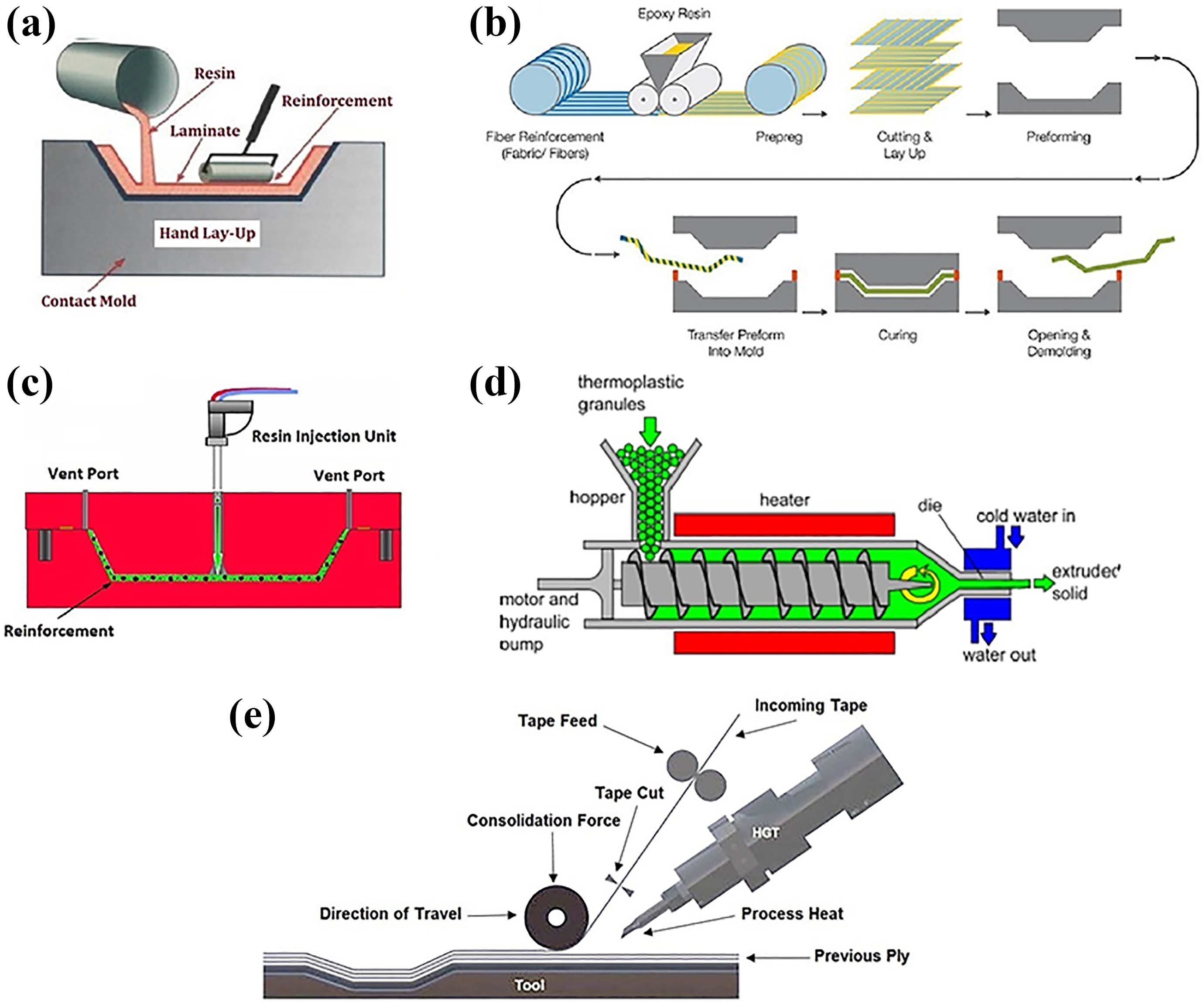
Manufacturing techniques for NFRC. (a) Hand layup process, (b) compression molding, (c) resin transfer molding, (d) extrusion process, and (e) automated fiber placement. 56
Hand layup
The hand layup is the oldest and most basic manufacturing method for composites, which basically involves manual placement of fabric layers, or plies in the mold and succeeding application of resin matrix to form a laminate stack. The wet composite is then rolled, brushed, or squeezed using hand rollers to distribute the resin uniformly, remove entrapped air, and consolidate the composite layers to ensure better interaction between the reinforcement and the matrix and to obtain the desired thickness. Generally, the hand layup manufacturing process can be divided into four elemental steps: mold preparation, gel coating, layup, and curing. This process is labor-intensive where the laminate quality, resin mixing, and laminate resin contents are highly depending on the operator skills, as in this method not much fiber loading is possible. 56 However, longer fibers can be used in this process and its versatility and low tooling cost has made it attractive for applications in marine and aerospace structures. Bulletproof composite panels were fabricated by the hand layup process from ramie fiber–reinforced composites with epoxy as a matrix. 57
Compression molding
Compression molding (CM) is the most common choice for high-volume composite parts normally used for thermoplastic and thermosetting matrices with long or short fiber even randomly oriented. By the use of this fabrication method, nearly 70 wt% of fibers could be incorporated and the thickness of between 1 mm and 10 mm can be achieved. The CM process is similar to the hand layup technique, except for a set of matching dies which remain closed before a cure takes place by means of applying pressure. For small-sized composites, CM is mostly preferred, while for larger parts hand layup and open molding are more favored. Fabrication of NFRCs through the CM technique can be done in two different ways, namely cold compression and hot compression process. In the cold compression process, only pressure is applied and curing takes place at room temperature, while for hot compression pressure and temperature are applied together and curing takes place by applying heat to the mold. 56 In CM, high-quality composites can be fabricated by controlling several key process parameters such as pressure, curing time, holding time, viscosity, and curing temperature considering the types of fiber and matrix. These parameters need to be carefully selected for the desired composite parts. Temperature, in particular, needs to be considered carefully as generally there is a slight difference in temperature at which a particular matrix can be processed and that at which fiber degradation will occur. 20 It has been shown that reduction in tensile strength of fibers normally occurs in a temperatures range from 150°C to 200°C, with strength dropping by 10% in only 10 min. 58 Overall, in order to avoid fiber degradation and achieve proper wetting, there should be a compromise between process pressure, curing temperature, and time which would vary with the different type of material used and the thickness of the sheets or plies.
Extrusion
The extrusion process can be used to fabricate FRC materials by pushing or pulling a material in a uniform cross-sectional area through a given die. This is achieved by softening the matrix material, usually in the form of pellets or beads, and mixing it with a bundle of fibers which are continuously transported into a single- or twin-screw extruder. Extrusion is a simple process that can be effectively used for renewable polymers such as PLA and cellulose-based polymers. Good fiber dispersion is crucial to aim for superior material performance, and twin-screw extrusion is a high shear process suitable for achieving good fiber dispersion. The fiber length measurements after the extrusion process indicated that there is an evident connection between the fiber length after extrusion and the toughness of the fibers as well as the impact strength of the composite. 59 Good fiber dispersion is crucial to aim for superior material performance, and twin-screw extrusion is a high shear process that can help to match good fiber dispersion. 60 Figure 7 presents the most cost-effective manufacturing techniques by production volume as well as their main advantages and drawbacks in fabrication of composite materials.
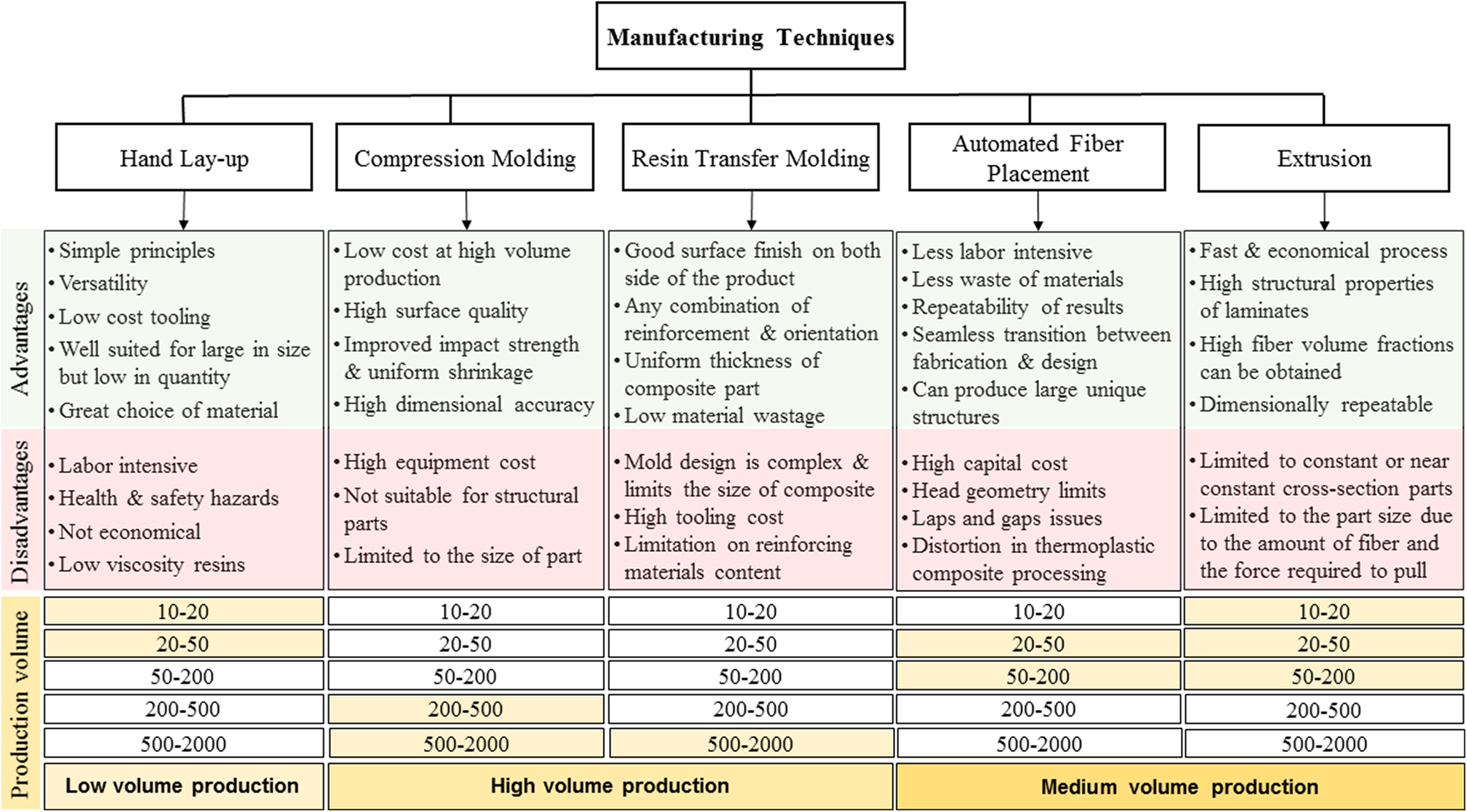
Advantages, disadvantages, and most cost-effective production volume of various composite fabrication techniques.
Resin transfer molding
Resin transfer molding (RTM) is designed for the impregnation of multiple fiber reinforcement performs, either long or woven fibers, within a mechanically clamped, rigid, closed mold. The liquid resin is injected into a mold under pressure and in some cases vacuumed, which is then maintained throughout the polymerization process. The most commonly used resins in this process are epoxy, vinyl ester, phenolic, and polyester. Several variables are closely related to the RTM process including injection pressure, resin characteristics, resin preheated temperature, mold configuration, and fiber preform architecture. 61 The selection and design of the process critical variables are needed in the process development stage to gain good component properties required by the end use application. Numerous studies have been performed concerning the potential of natural fibers as reinforcement with renewable polymers as matrix through RTM. 35,62 –64 The advantages of this process are considerable when compared to other processes including lower temperature requirements, less material waste, almost zero air entrapment, avoidance of thermomechanical degradation and it is suitable for manufacturing large, complex parts with high strength-to-weight ratio. In this process, the structure of natural fibers including the effect of lumen closing determines the compaction and as a result natural fiber composites are less compactable than glass fiber composites due to lower degrees of fiber alignment. 62 The mechanical properties of sisal fiber–reinforced composites fabricated by RTM and CM methods have been investigated. The experimental results revealed that the tensile strength, Young’s modulus, flexural strength, and flexural modulus of RTM samples are higher than CM samples. This can be attributed to the lower void content and water absorption characteristics of composites fabricated by RTM due to good fiber/matrix interaction when compared to CM. 65 In brief, RTM is a versatile manufacturing method that can be used to manufacture large, complex parts with high strength-to-weight requirements from a wide choice of reinforcements, thermosets, and fillers.
Automated fiber placement
Automated fiber placement (AFP) is an advanced method to fabricate large and complex composite structures. The productivity of the manual hand layup can be automated using a controllable robotic system. This method uses a robot to place the continuous fiber–reinforced composite tape and build a structure one layer at a time. In the AFP process, the incoming tape is heated through the use of hot nitrogen or a laser and then each tape is pressed to the mold by a roller for suitable compaction as shown in Figure 6. Highly customized parts can be fabricated by AFP technology as each ply can be laid with different orientation and angle, to best carry the required loads. 66 The main advantages of the AFP system are producibility, repeatability, and considerable reduction in labor costs, material scrap, and manufacturing time compared to other manufacturing methods. This technology has become more popular and affordable these days, as several Western aerostructures manufacturers in the aviation industry such as Boeing, Spirit, and Airbus have got equipped and successfully incorporated it for their products. However, several disadvantages and limitations are related to AFP such as mold shape, compaction roller diameter, head geometry limits and to ply edges created by cut tapes. 67
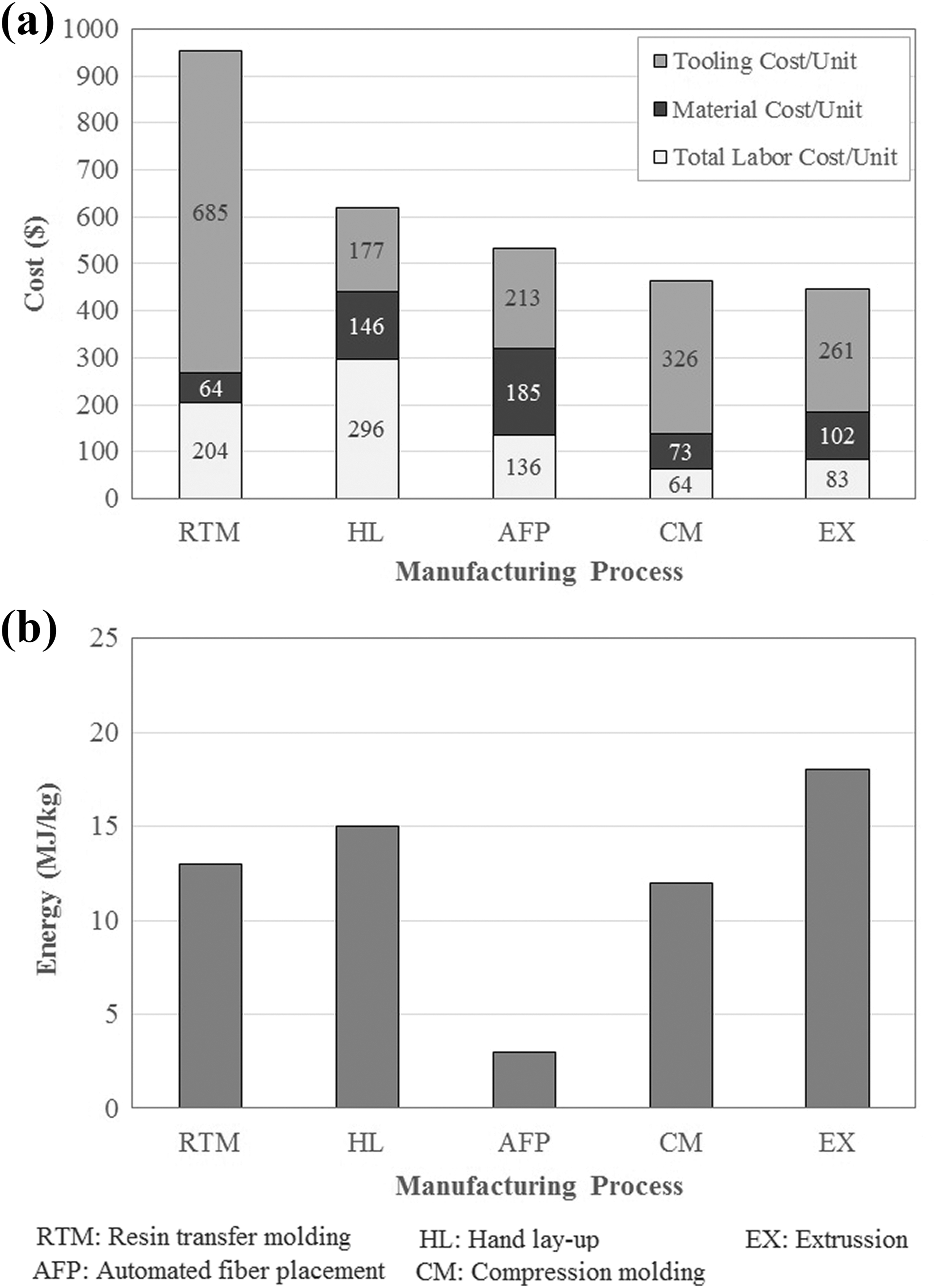
Figure 8(a) shows the estimated per unit cost at unit 100, amortizing tooling and setup in order to fabricate a FRC. The chart also shows the cost contribution from tooling, labor, and material. A comparison of the energy intensities in the manufacturing is shown in Figure 8(b). The high energy intensity requirement of the extrusion process has driven the current increased focus on processes such as RTM and CM. Up to the present time, CM, injection molding, and RTM are the main manufacturing methods for NFRCs, but in the past few years the manufacturing and processing technologies for bio-composites have also developed considerably. Accordingly, new downstream and auxiliary equipment as well as new configurations of feeding systems have been designed and developed such as combinations of different manufacturing processes like extrusion-injection molding or extrusion-compression molding with different screw, mold, and die design. 3
Machining and machinability of NFRCs
Composites are fabricated using various fabrication methods, as mentioned in the previous section, to a near-net shape final product. However, they still need some secondary operations since they cannot be welded together or glued without difficulty to achieve the specific final shape and required tolerance. Thus, the machining process is the common solution to facilitate joining of composite components to other parts in complex assemblies. 70
Conventional drilling
Among various drilling operations that have been used to make holes in composite laminates, conventional drilling (CD) is still the most widely used method in industry to date. CD operations mostly cover mechanical drilling, vibration-assisted twist drilling, and high-speed drilling (HSD).
Mechanical drilling
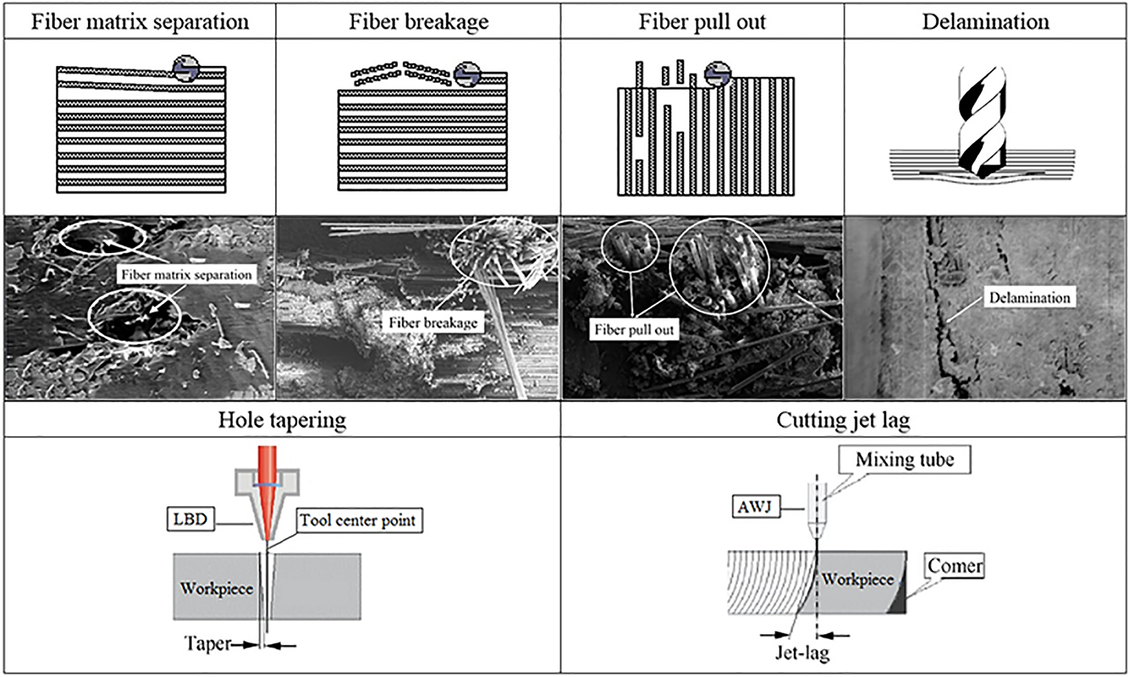
Mechanical drilling is the most frequently used machining operation, as it is a cost-effective process compared to other methods, considering that there are not many other methods that can produce deep circular holes. The holes required by mechanical joining by means of bolted joints and rivets during the assembly of parts with other components are commonly drilled in the semifinished composite part. 56 Owing to some specific characteristics of composite materials such as anisotropy, inhomogeneity, and high abrasiveness, the drilling operation of composites is considered to be difficult. 71 The most frequent damages that affect the quality of the drilled holes are delamination, fiber/resin pullout, fiber matrix separation, and interlaminar cracking, in addition to some other minor undesirable damages such as cutting jet lag and hole tapering in nonconventional machining methods, as shown in Figure 9.
There have been many different tool geometries such as twist, step, slot, dagger, core, brad and spur, and straight flute drill bits with different point angles made of various materials such as high-speed steel (HSS), solid carbide, coated cemented carbides, uncoated cemented carbides, and polycrystalline diamond used in mechanical drilling of NFRC laminates. The material and geometry of the drill bits play an important role in improving the machinability of the NFRCs in several aspects such as reducing drilling damages, enhancing the quality of the drilled holes, and extending tool life. Twist drills made of HSS or carbides tool materials are the first attraction in mechanical drilling of NFRCs among other drill bits. It has been reported that the drilling damage tendency at hole entry and exit decreases with increasing point angle. 75 Table 4 lists some of the reported drilling conditions by several researchers and their concluding remarks when drilling various NFRC laminates. As can be seen from the table, because of different properties presented by different natural fibers and matrices, as well as their different manufacturing methods, it is hard to provide particular guidelines on selecting the important process parameters in order to improve the machinability of these composites. Generally, higher cutting speed, lower feed rate, smaller drill diameter, and point angle of 118° result in good quality holes with low delamination. 86
Drill bit geometry and materials used by different researchers for drilling of NFRCs.
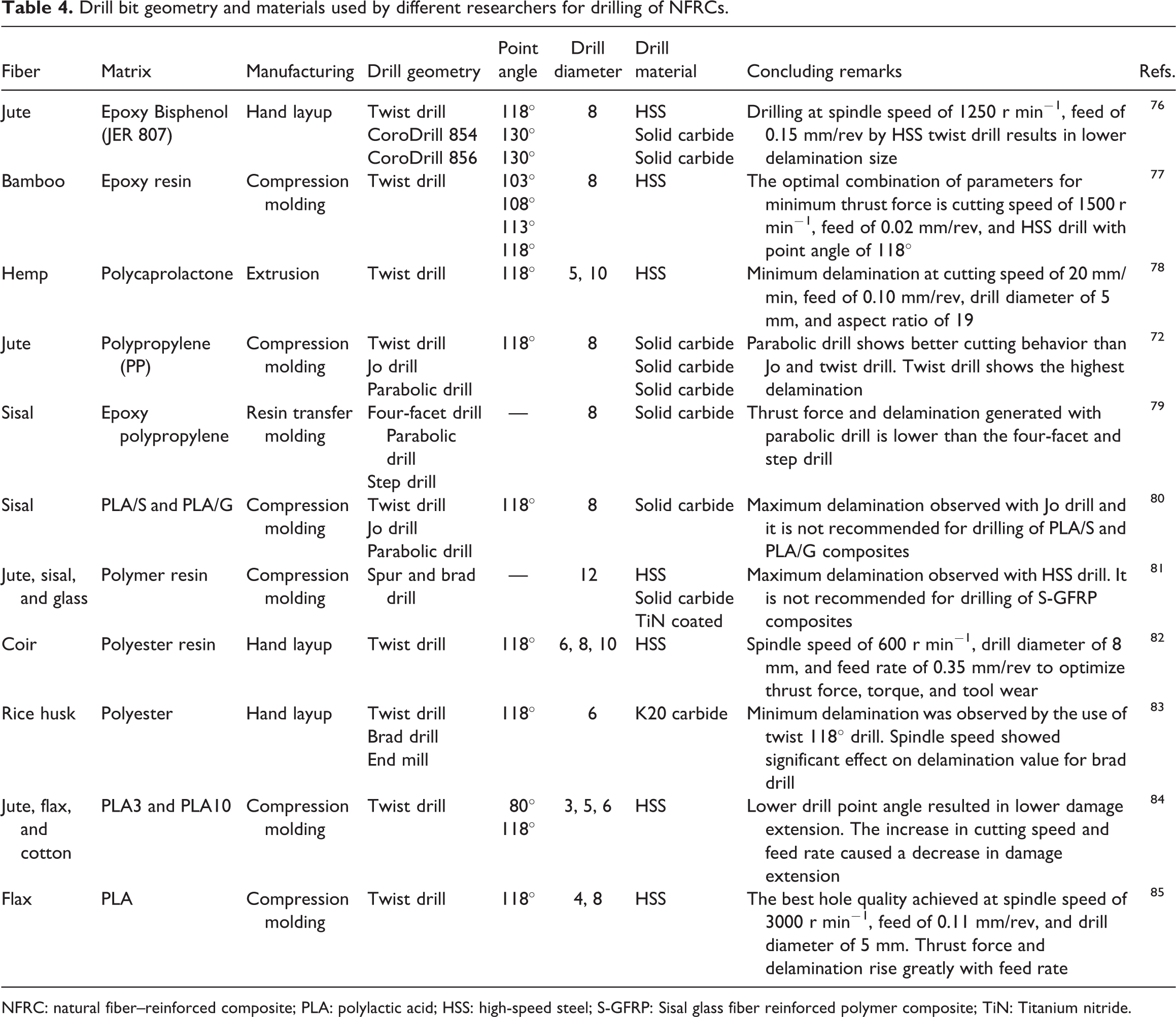
NFRC: natural fiber–reinforced composite; PLA: polylactic acid; HSS: high-speed steel; S-GFRP: Sisal glass fiber reinforced polymer composite; TiN: Titanium nitride.
It is estimated that 60% of all part rejection are due to the poor hole quality, and since holes are drilled in the last phase of production, rejection of parts due to poor hole quality leads to a severe economic loss. 87 A large number of experiments were conducted to minimize the drilling-induced damages of NFRCs and to investigate the influence of input process parameters on output variables such as delamination, tool wear, and thrust force, which are discussed in more detail in the next section. 78,88 –91
Vibration-assisted drilling
The high rejection rate of drilled composites due to the drilling-induced damages around the hole drives engineers and academicians to use an alternative technique for reducing undesired damages. The schematics of the drilling setup and mechanism are shown in Figure 10. The vibration-assisted drilling (VAD) technique has presented a great potential in drilling composite materials in the past few years through the significant reduction of cutting forces, delamination, and tool wear. 92,93 However, VAD is basically different from conventional mechanical drilling. The mechanical drilling is a continuous process, while the VAD is a pulsed intermittent cutting process, which uses a piezoelectric crystal oscillator to induce the vibration on tool or workpiece to make discrete contact between them.
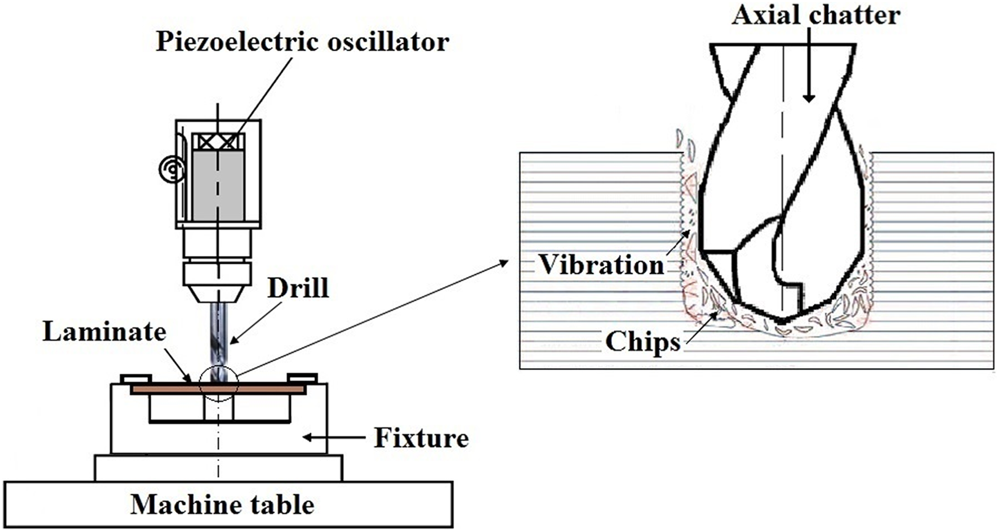
The schematics of vibration-assisted drilling.
Both theoretical predictions and experimental outcomes have shown that the quality of the drilled surfaces can be significantly improved by reducing the axial thrust force exerted by the drill bit on the composite. Thrust force has been found as the empirical reason of delamination in polymeric composite materials. VAD uses the regeneration effect to make axial chatter, facilitating chip breakage and relatively lower axial thrust force which reduces delamination and other related damages in composite laminates. From the experimental results, it was found that vibration drilling can reduce nearly 50% of cutting temperature and 20–40% of less delamination without affecting productivity in comparison to mechanical drilling. 94 Moreover, applying low-frequency vibration during machining makes the tool wear, cutting temperature, and delamination decrease with a subsequence increase in tool life and drilling efficiency, which makes this method suitable for drilling holes on FRCs.
High-speed drilling
HSD is known as one of the key machining technologies capable of improving process productivity and lowering damages induced by drilling of composite materials. Unlike conventional mechanical drilling, HSD of composite materials is very costly as the drilling operation has to be conducted on an especial high-speed machine which is very expensive. However, similar to VAD, HSD provides better quality of drilled holes along with high efficiency and less delamination. It has been revealed that the delamination tendency decreases with increased cutting speed during HSD of composite laminates due to the reduction in cutting forces. 95 A number of experiments have been conducted to investigate the effects of major drilling parameters such as feed rate, spindle speed, drill type, and drill bit point angle on delamination during HSD of composite materials with a maximum spindle speed of 40,000 r min−1 . 95 –98 The experimental results have indicated that larger material removal rates are correlated with minimal delamination, irrespective of the feed speed applied and the delamination tendency decreases as the spindle speed elevates. This happens due to the increase in cutting temperature with an increase in spindle speed, thus endorsing the softening of the matrix and inducing less delamination. 99 However, in HSD, thermal softening of the tool material and the abrasive chip-type are the main reasons for tool wear. While tool wear occurs, axial thrust force will increase with subsequent effect on the tool life with respect to the number of holes. 100
Nonconventional drilling
Considering the damages generated by CD methods such as cracking, chipping, delamination, and high tool wear, particular attention should be given to other novel and nonconventional processes to create a good quality hole-like feature in FRC laminates.
Ultrasonic drilling
Ultrasonic drilling (USD) is a nonconventional method of drilling in which electrical energy is transformed into mechanical vibrations by the use of a transducer, which are then transferred to the energy-focusing tool. USD has significant advantages over CD technique such as improved surface roughness and less delamination damages. This method has been effectively used for drilling of conventional FRP composites and metal matrix composites to improve the quality of drilled holes. It has been found that applying ultrasonic vibrations during drilling of FRP composites decreases the drilling forces (thrust and torque) and burr formation, which results in outstanding reduction in both drilling-induced delamination and surface roughness defects up to 50%. 94,101 This considerable reduction in thrust force can be attributed to the chip breakage and the reduction in friction because of ultrasonic vibrations. In drilling operation, the cutting speed around the chisel edge area is very low and consequently the back rake angle is negative. This results in an increase in thrust force in this area. In USD using ultrasonic vibrations with proper amplitude, an impact regime in this area reduces thrust force by making cracks in reinforcement fibers. 102 Force reduction generally improves the quality of drilled holes and surface finish, and reduces power consumption and production cost. The most outstanding comparative advantage of USD compared to other techniques is it neither generates thermal, chemical or metallurgical damage on the workpiece nor produces remarkable residual stress, either aspect is substantial for the reliability in service. 10 However, the setbacks of modern USD are that it is a slow process owing to its low material removal rate, the machining setup is considerably expensive, and it is less economical compared to other nonconventional methods such as laser drilling or abrasive water-jet machining in case of single-hole production but not in multi-hole production.
Laser drilling
Laser beam drilling, as a noncontact material removal process, provides a solution to some of the critical difficulties that conventional machining processes can result in. Laser drilling of composite laminates has recently found wide applications in numerous fields of industrial applications due to the good quality of cut surface, low production cost, and short processing time. The Nd: YAG laser is the main laser used for laser drilling of metal matrix composites, and CO2 laser is mostly used for cutting FRP and graphite/epoxy composites. 103 Laser drilling offers a variety of advantages over CD as it is a noncontact, abrasion less technique that eliminates tool wear, machine-tool deflections, vibration of drill bits, and delamination caused by thrust force. Lasers can also be used for almost all types of materials. Although interesting for the absence of tool–material interactions, laser machining presents some notable drawbacks that must be attentively considered. The main limitation in laser drilling is the maximum thickness which can be cut with an acceptable quality. Above 5–10 mm thickness, especially in holes with a large aspect ratio (H/D), an extensive undesirable taper may take place. Moreover, laser drilling for composite materials is far more difficult since laser machining is a thermal process, and composite constituents usually have different thermal conductivities, heat capacities, and vaporization temperatures. 104 During the laser process, the temperature at the ablation front may not surpass the vaporization temperature of fibers, but it is considerably higher than the temperature of degradation or decomposition of the polymer, which results in surface deterioration and polymer burnout. 105 Many experiments indicated that good quality of the holes can be achieved when the thermal conductivity of the reinforcing fibers and matrix are close together.
Other machining processes
Near-net shape composites require fewer machining operations than standard materials, which reduces the need and thus the cost of machining processes. However, several machining processes such as turning, milling, grinding, and trimming are commonly used for machining composites in order to facilitate joining of parts to meet dimensional and assembly requirements or required tolerance in many industries dealing with these materials.
Milling
After the drilling process, milling is the most common machining process mainly as a corrective operation to create high precision and quality surfaces in various composite materials. However, during milling operation, damages can be induced to the surface in the forms of delamination, microcrack, fiber pullout, and matrix burning, which have detrimental effects on the performance of the composite materials. 70 The quality of the machined surface of NFRCs considerably depends on the nature of fibers on the one hand and the thermal stress on the contact surface caused by friction between the tool and the material on the other hand. Thermal stress on tool becomes more crucial when a tool with low heat capacity and a small diameter is being used for machining NFRCs which are generally characterized by their low thermal conductivity. The heat generated during the machining process cannot be absorbed by the milling tool due to low heat capacity and results in greater thermal stress, more tool wear and as a result lesser operational safety. 106 The experimental results indicated that low feed rate leads to a minimum surface roughness in milling of kenaf fiber–reinforced composites while the cutting speed did not affect the surface roughness considerably. 107 Nonetheless, a greater depth of cut and high cutting speed is found to produce product with a good surface finish. High cutting speed, low feed rate, and medium depth of cut are reported as the optimum machining conditions in milling of woven jute natural fiber composites to obtain less delamination and superior surface roughness. 108
Turning
As mentioned earlier, most NFRC components do not need secondary machining operations such as turning except for finishing requirements. Turning is not a cost-effective process and very few investigators have studied the machinability of NFRCs in turning. Most of the studies on turning operation have shown that minimizing the surface roughness is a difficult task. The machined parts have poor surface finish due to the inhomogeneous microstructure of reinforcing fibers and abrasiveness of these materials. 109 According to an attempt that has been made to investigate the effect of rotation speed in the range of 450–1400 min−1 and feed rate in the range of 0.1–0.61 mm on wood plastic bio-composite while depth of cut was remained constant, it is recommended to use higher tool nose radius, higher cutting speed, and lower feed rate to obtain better quality of surface finish. 110 In addition, application of a tool with a linear cutting edge can help achieve better quality of surface roughness. 111 The surface roughness is the major significant factor affecting coating performance in turning of the NFRCs. 112
Machining-induced defects and contributing factors
In this section, challenges related to machining of NFRCs and the induced damages are discussed. Generally, the machining process is applied to produce the desired shapes within the prescribed dimensional tolerances and achieve high surface quality. The general defects originated by the manufacturing and machining process are matrix imperfection, poor and rich resin area, interlaminar cracks, voids, debonding, burrs, delamination, and thermal damage.
Delamination
Among the defects associated with machining, delamination is found to be the most critical one. 71,99 Delamination is mainly an inter-ply failure phenomenon induced by an exterior force, such as drilling, which results in separation of different layers of reinforcement or plies. Delamination has been found as a major concern during drilling of composite laminates as it can result in a drastic reduction of structural integrity, assembly tolerance, surface finish quality, and bearing strength. 113,114 There are two distinguishable delamination mechanisms associated with the drilling of FRCs known as “peel-up” delamination which occurs around the periphery of the drill entrance and “push-out” delamination which occurs at the exit of the drilled holes periphery, as shown schematically in Figure 11. Peel-up occurs when the cutting edge of drill touches the composite laminates, the abraded material is pulled along the flute and spirals up before being effectively cut. This action generates a peeling force in the axial direction through the slope of the drill bit flutes which separates the upper plies from each other forming a peel-up delamination zone at the top surface. Peel-up delamination is not always appearing at drill bit entry as the peeling force is a function of tool geometry and friction between the tool and workpiece. 115,116 As the tool further advances to the exit plane, the thickness of uncut piles beneath the drill becomes smaller and resistance to deformation decreases. Eventually, at some point, the thrust force applied to the uncut plies exceeds the interlaminar bonding strength of the material, and pushdown delamination occurs. It has been widely reported that the pushdown delamination is more extensive than that associated with the peel-up. 117 While the level of peel-up damage mostly depends on cutting speed and drill bit point angle, that of pushdown is dependent on the feed rate and drill diameter. Moreover, natural fibers such as flax or kenaf react differently to the applied thrust force in comparison to that of synthetic fibers. This can be attributed to the soft nature of natural fibers, mainly due to their high cellulose content, thereby the energy can greatly be dissipated through fiber deformation in contact with a solid drilling tool. 118 This feature enables the natural fibers to deform under the interaction with cutting tool and limit any failure because of the fiber brittle fracture. 119 Nevertheless, in order to overcome such difficulties, developing a proper procedure and selecting precise cutting parameters are absolutely crucial.
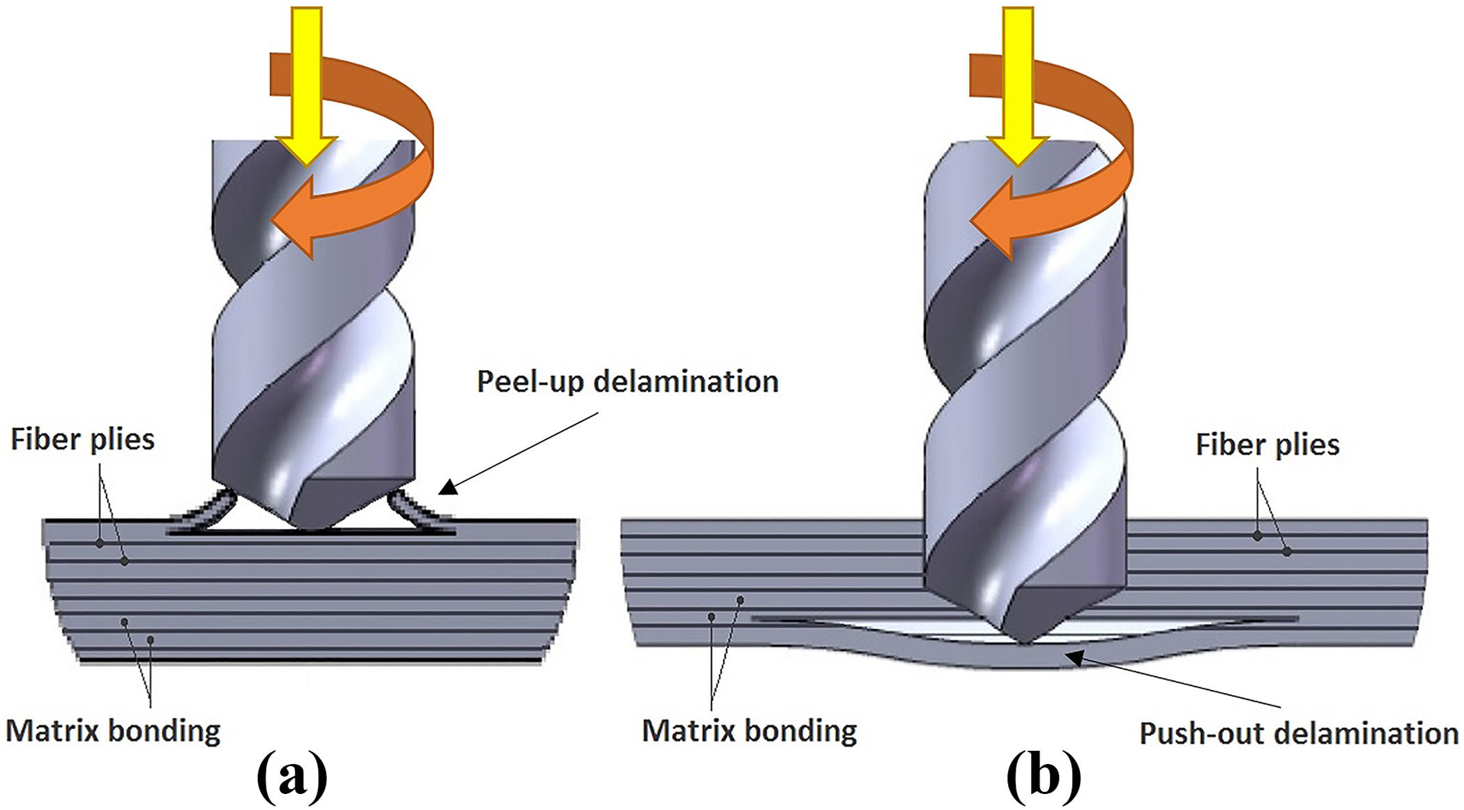
Mechanisms of delamination (a) peel-up at entrance and (b) pushout at exit.
Delamination assessment
Delamination assessment in NFRC materials is a rather challenging task, especially for dark fiber–reinforced composites since their color makes the visual inspection difficult. There exist various dimensional and nondimensional measures used to evaluate the degree of delamination damage. Among different techniques employed to assess delamination, delamination factor is an important parameter. The one-dimensional delamination factor (Fd) is described as the ratio of the maximum diameter of the observed delamination (Dmax) to the nominal diameter of the drill hole (Dnom), 120 as shown in Figure 12. It is calculated using the below equation
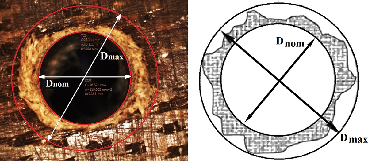
Scheme of evaluation of one-dimensional delamination factor.

However, the conventional delamination factor might give a higher value of delamination because just a few fibers can make a large radius with little delamination of the drilled hole. Hence, the following two-dimensional delamination factor (Fa) was proposed to consider only the damaged area 121

where Adel is the delamination damage area and Anom is the nominal area of the drilled hole. The conventional delamination factor (Fd) does not truly depict the real delamination zone of the hole because it does not consider the area of delamination, and the two-dimensional delamination factor method takes the damage area into account but neglects the maximum crack length while assessing the delamination factor. Hence, a new and better approach than abovementioned methods was suggested to calculate the delamination factor named as adjusted delamination factor (Fda). The first part of equation (6) reflects the length of cracks contribution, and the second part represents the extent of the damage area contribution
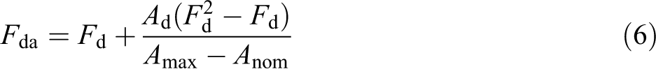
where Fd is the conventional delamination factor, Ad is the area of the delamination zone, Amax is the area related to Dmax, and Anom is the area corresponding to Dnom. The adjusted delamination factor found to be more precise than earlier methods. However, this method may still be inaccurate and tends to give a larger value due to its additive formula. Thus, equivalent delamination factor (Fed) was proposed and it is calculated using the below equation 122
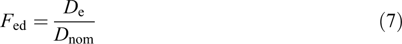
where
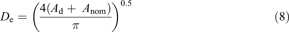
Although equivalent delamination factor appears to be a better method for measuring delamination, it does not reflect the severity of damage accurately. Hence, refined delamination factor (Fdr) was proposed as another measure. 123 In this method, the total damage area is divided into three areas, namely heavy damage area (AH), medium damage area (AM), and low damage area (AL), as it is shown in Table 5. The parameters used in equation (9) are arrived by analyzing the captured delamination images in seven different stages using the concept of neural network with MATLAB 7.0 tool
Evaluation of delamination factor using various methods.
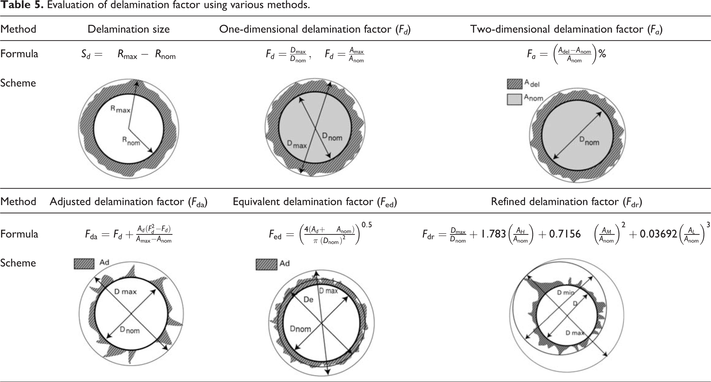

This factor is found to be better than previously mentioned factors in delamination assessment as it considers all the elements of delamination damage. Table 5 consolidates the various assessment methods and equations used for assessing delamination.
Many studies by various researchers have illustrated several non-destruction techniques for measuring delamination damage in composites to obtain dimensional parameters like length, shape, area, and size of delamination, which include optical microscope, 114,124,125 ultrasonic C-scan, 122,126,127 acoustic emission (AE), 128,129 digital image processing technique, 99,130 –132 shadow moiré laser based imaging technique, 133 and X-ray computerized tomography. 130,134,135 Among these, digital image processing and microscopy are the most commonly used and cost-effective techniques for measuring the radius or diameter. Developments in digital image processing have made processing and analyzing of the captured images more reliable.
Effects of input variables on delamination
The quality of the drilled holes, especially in terms of delamination, has been shown to be strongly dependent on the machining input factors such as spindle speed, feed rate, drill diameter, drill bit geometry, and drilling operation condition. It has been reported by many researchers that delamination increases with feed at any cutting speed using various drill bits. This is mainly due to the increase in cutting forces with increasing feed during the drilling process. Thrust force is considered as the main reason for delamination and it is believed that no peripheral damage around the drilled hole occurs below critical thrust force. Therefore, delamination typically results from excessive thrust force during drilling operation. 10 The experimental results indicated that the influence of spindle speed on the thrust force and peripheral damage was not that considerable for any of the drill types tested, while the feed rate was found to play the main role on the responses such as thrust force, torque, and delamination damage area. 26,131,136 It has been revealed that the thrust force and consequently the delamination tendency decrease slightly with an increase in cutting speed. Higher spindle speeds will lead to lower forces, according to the general principle of high-speed machining, and hence lesser delamination damage is expected. 76 However, the results of few research are not in agreement with this trend, and they noticed in their experimental work that the extent of delamination damages raised with increasing cutting speed during CD of composites. 73,137,138 These differences in the observed trends cannot be reflected as contradictions but as subjective depending on several different issues. For instance, tool wears out more quickly at higher cutting speeds, which can lead to increased thrust force and torque. The generated torque during drilling is also correlated to the feed and increases with the increase in the feed rate. Toward the end of drilling, torque may raise up dramatically because of chip blockage in the helix. 139
The key for overcoming drilling-induced delamination to achieve better drilling accuracy lies in decreasing thrust force and torque by optimizing the input parameters. A clear rise in the torque value was seen by increasing the diameter of drill for all drilling speeds owing to the fact that higher shear force is required for cutting the materials from the hole. Many investigations reported that the optimum setting of the input parameters is a combination of moderate diameter of the drill bit, lower feed rate, and higher spindle speed, which results in minimum delamination and long tool life. 70,81,87,140
Surface roughness
The surface quality of the machined composite component is very important in the assembly of mechanical parts and is an indicator of exactness of the manufacturing process. The performance of the machined parts along with the cost of production is notably affected by the produced surface roughness. 141 In drilling, surface roughness is a very important quality as the mechanisms of creep, wear, fatigue, and corrosion depend on it and it also demonstrates the level of irregularity on circumferential walls of the drilled holes. 142 The quality and performance of a composite product is highly dependent on the surface condition created by machining. In the milling process, surface finish is normally expected as a main manufacturing goal particularly in edge trimming operation. Good surface finish not only ensures the product quality, but also decreases the cost of manufacturing. Thus, surface finish roughness/quality can be considered as an important issue in the field of engineering machining, which can noticeably affect the functioning of composite parts as well as cutting parameters and machine selection during the planning process. 143 Therefore, several researchers studied the effect of machining factors like feed rate, speed, and drill diameter to optimize the machining process in order to obtain a superior surface roughness. It was found that the value of surface roughness (Ra) increases with the feed rate unlike the cutting speed; an increase in cutting speed causes a decrease in surface roughness. This behavior is mainly due to the decrease in cutting forces. Hence, better surface finish can be achieved at higher cutting speed and lower feed rate. The experimental results also indicate that at low feed, the values of Ra increase with the increase in diameter of the drill. This happens as a result of an increase in thrust force and torque as well as the generated temperature around the tool edge which ruins the stability of matrix and creates fuzzy and rough cuts. However, further increasing of drill diameter at some point may also result in better surface roughness once the cutting temperature reaches the composite transition temperature (Tg) in which the composite will transition from a glassy state to a rubbery state. At this stage, matrix can deform easily and make a smooth cutting surface. 115 Drill diameter combined with feed rate has a greater effect on delamination and surface roughness when it is compared to spindle speed during drilling of hemp fiber–reinforced composite (HFRC) laminates. 81 The experimental results showed that HFRC recorded the lowest delamination factor and surface roughness in comparison to glass, jute, and banana fiber–reinforced composites. 144 Moreover, apart from drill diameter, the drill geometry is found effective on the surface quality of the holes in the drilling of NFRCs. Increasing the number of flutes results in increased surface roughness due to the increase in tool–material contact per unit of time. Most of the results have proved that at higher spindle speeds, lower feed rates, lesser drill diameters, and point angles, the removal of fibers from the matrix is completely sheared resulting in relatively good surface finish. 131
Tool wear
In all machining processes, tool wear is one of the major features to assess the machinability of materials. In fact, minimum tool wear is an indicator of good surface quality of the drilled hole. 141 Tool wear during the drilling process can result in serious damages such as delamination, which has a substantial economic impact. Excessive tool wear, in particular, is one of the major reasons for high cost of drilling long NFRC as the number of holes which can be drilled with one particular tool is limited. 145,146 The major reason for tool wear is the rise in temperature and thermal softening of the tool material, as well as the abrasive nature of the chips. Basically, there are two main regions of tool wear in a cutting tool, that is, flank wear on the tool flank face and crater wear on the tool rake face. 56 The main wear mode in drilling of FRCs is flank wear, which occurs because of sliding contact with the hard and abrasive reinforcing fibers. However, less tool wear was observed in NFRCs since natural fibers, in general, are less abrasive than their synthetic counterparts due to their lower strength. 147 In drilling of composites, tool wear appears in different several ways, depending on the geometry and material of drills, various material combinations of workpiece and drilling parameters. There are three tool wear mechanisms associated with drilling of composite laminates, namely abrasive wear, chipping, and adhesion. The abrasive wear mechanism is a mechanical wear characterized by scratching of reinforcing fibers inside the soft polymer matrix in the sliding direction. 148 Based on investigations, 124,149 tool wear is not uniform along the edge and it can generally be divided into three different regions: primary region, secondary region, and tertiary region. In primary or initial wear region, during the start of drilling, tool wear is mainly caused by chipping which can clearly be noticed at rake face, chisel edge, secondary cutting edge, and corners. Chipping appearance may be because of relatively hard fibers. In secondary or steady wear region, abrasive wear can be seen on flank faces and in severe wear region, adhesion wear with microchipping appears on the flank face of cutting tool due to the high temperature built up on the tool as shown in Figure 13. Among different tool wear mechanisms, flank wear was found to be the most dominant wear mode under most drilling conditions. 120,150
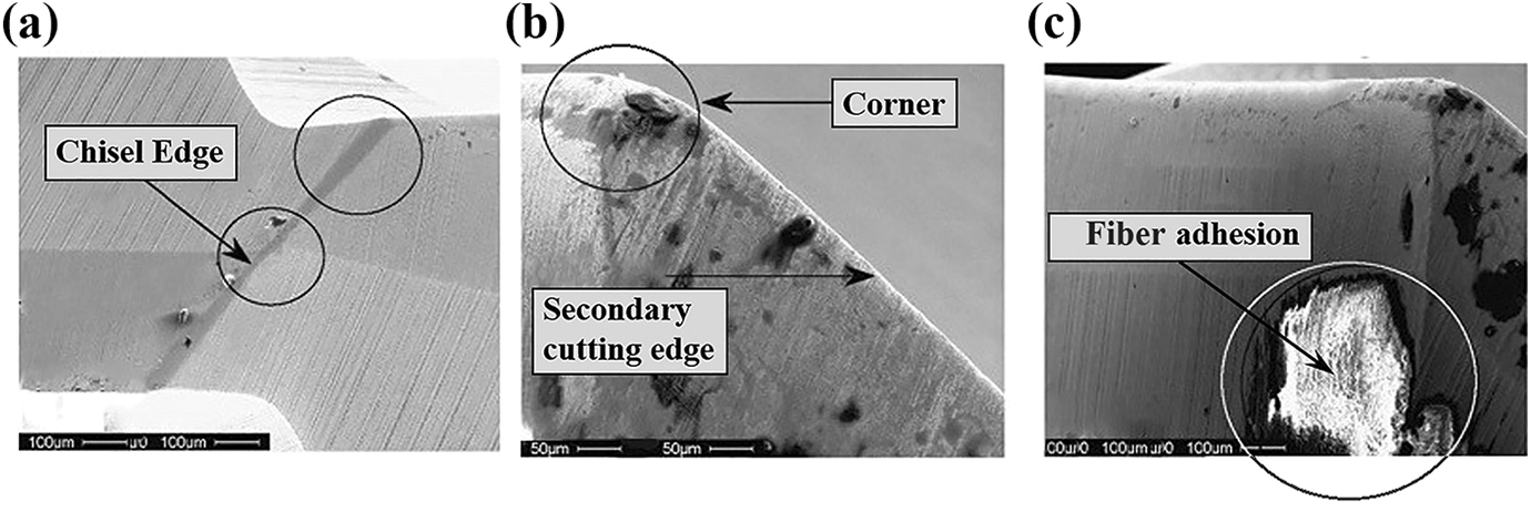
Scanning electron microscope (SEM) images of tool wear viewed in drilling using a cemented carbide (WC) drill at spindle speed of 15,000 r min−1 and feed rate of 0.1 mm/rev: (a) chisel edge aggressive abrasive wear, (b) flank wear on the secondary cutting edge and rounding of corner of drill, and (c) adhesion of reinforcing fiber on the flank face of the drill. 124
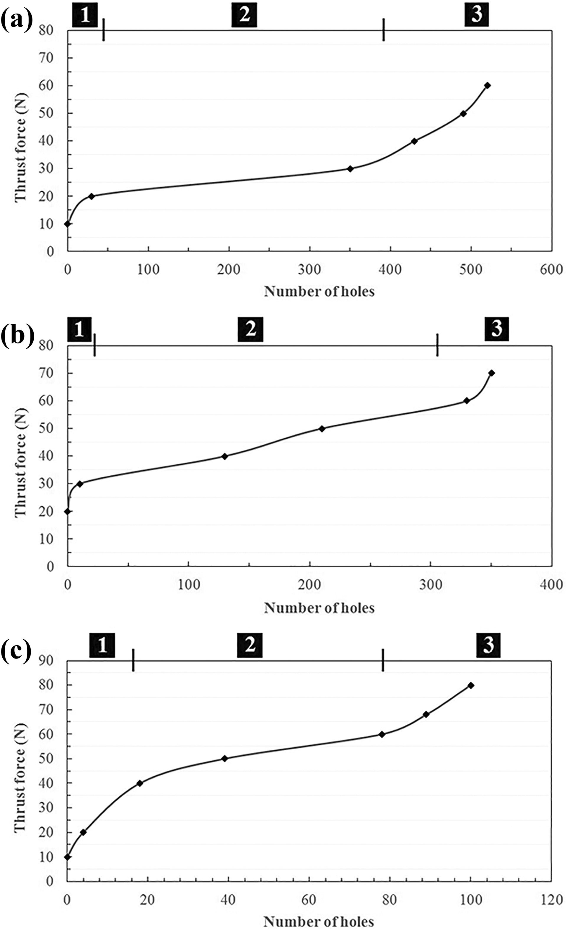
Tool wear is sensitive to change in drilling parameters such as spindle speed and feed rate. A clear relation was found between tool wear, cutting forces, and the quality of the drilled hole, in terms of dimensional accuracy and surface finish. In general, increasing cutting speed and feed rate increases cutting temperature and flank wear of drill bits and results in shortening tool life. It was found that optimum cutting values of parameters in drilling of coir fiber–reinforced composites using Nelder–Mead and genetic algorithm methods are lower drill bit diameter, lower speed, and moderate feed rate. 90,151 Accordingly, an increase in the flank wear results in a significant raise in cutting forces.
As mentioned earlier, tool wear affects the quality of surface finish and can result in serious damages in the composite laminates. Nevertheless, it was noticed that a steady increase in the rate of wear in both primary and tertiary regions affects the drilling force considerably, which in turn causes higher delamination at the hole entry and exit. Several studies have investigated the effect of the input variables and tool wear on delamination factor and the results indicated that tool flank wear causes a noticeable increase in delamination factor. This is mainly because thrust force increases with tool wear and it becomes more significant as the cutting speed increases. 71,116 Moreover, as the drilling operation goes further, with the increase in the number of drilled holes, hole surface roughness (Ra) was found to increase gradually due to the tool wear. When drilling operation commences, chipping appears owing to the sharp cutting edges of the drill bit. 152 The initial chipping together with increasing flank wear during drilling leads to a noticeable increase in cutting forces as shown in Figure 14. An increase in thrust force results in the appearance of microcracks at the ply interfaces and extensive fiber pullout, therefore deteriorating the final hole surface quality. 124 For a constant drilling process, when hole quality is reduced and maximum thrust force emerged, that means the end of tool life, that is, tool wear exceeds acceptable level. Therefore, by evaluating the thrust force with respect to the number of holes drilled, tool life can be predicted.
Online monitoring of machining-induced defects
There is a strong relationship between tool wear, thrust/cutting forces, and the quality of the drilled hole, in terms of delamination and surface roughness. Through online monitoring of the cutting forces and tool condition monitoring system, strategies can be designed to control and optimize the process for increasing the quality and productivity. Several types of sensors are available for monitoring the drilling operation such as accelerometer, AE sensors, spindle mounted strain gage sensors, vibration sensor of the tool and workpiece, and motor current sensors. 124 Among all the different types, AE sensor is considered to be the most suitable candidate in the field of machining composite materials because it is cost-effective and can evaluate the process without destroying the material condition or disrupting the operation. AE is regarded as an active intelligent indicator for monitoring damages in the drilling process. 153 AEs are transient energy waves generated by the sudden release from localized sources within a material undergoing stress or subjected to mechanical load. AE sensors can record high-frequency wave sources from matrix deformation, fiber cutting, matrix cracking, tool wear, and delamination. Once the signals are attained, a processing method should be implemented to characterize the AE signals by relating different damage mechanisms occurring during drilling of composites with specific signal features. It has been reported that either time domain statistical analysis or spectral analysis like Fourier transform is preferred when the signals are stationary. Figure 15 shows the waveforms and corresponding power spectrum of AE signals during drilling of different number of holes in FRC. It can be conferred from Figure 15 that by increasing the number of holes, both frequency and amplitude results change noticeably in value, which indicates the tool status deterioration. Changing the energy during the drilling of the 30th hole demonstrates the energy emitted from fiber–matrix debonding and related defects with frequency centered at about 80 kHz. At the start of drilling for the first hole, the cutting edges are sharp and the cutting process is basically smooth with no abrupt variation, thus producing uniform wavelet coefficients indicating cutting of fibers. As the number of drilled holes increases, the magnitude of wavelet coefficients increases, indicating deterioration in tool condition. 154 During the drilling of the 30th hole, an increase in the amplitude of wavelet coefficients along with the long duration of the frequency components indicates that the damages, like matrix cracking and delamination, continue for a while even after the fiber breakage. 155
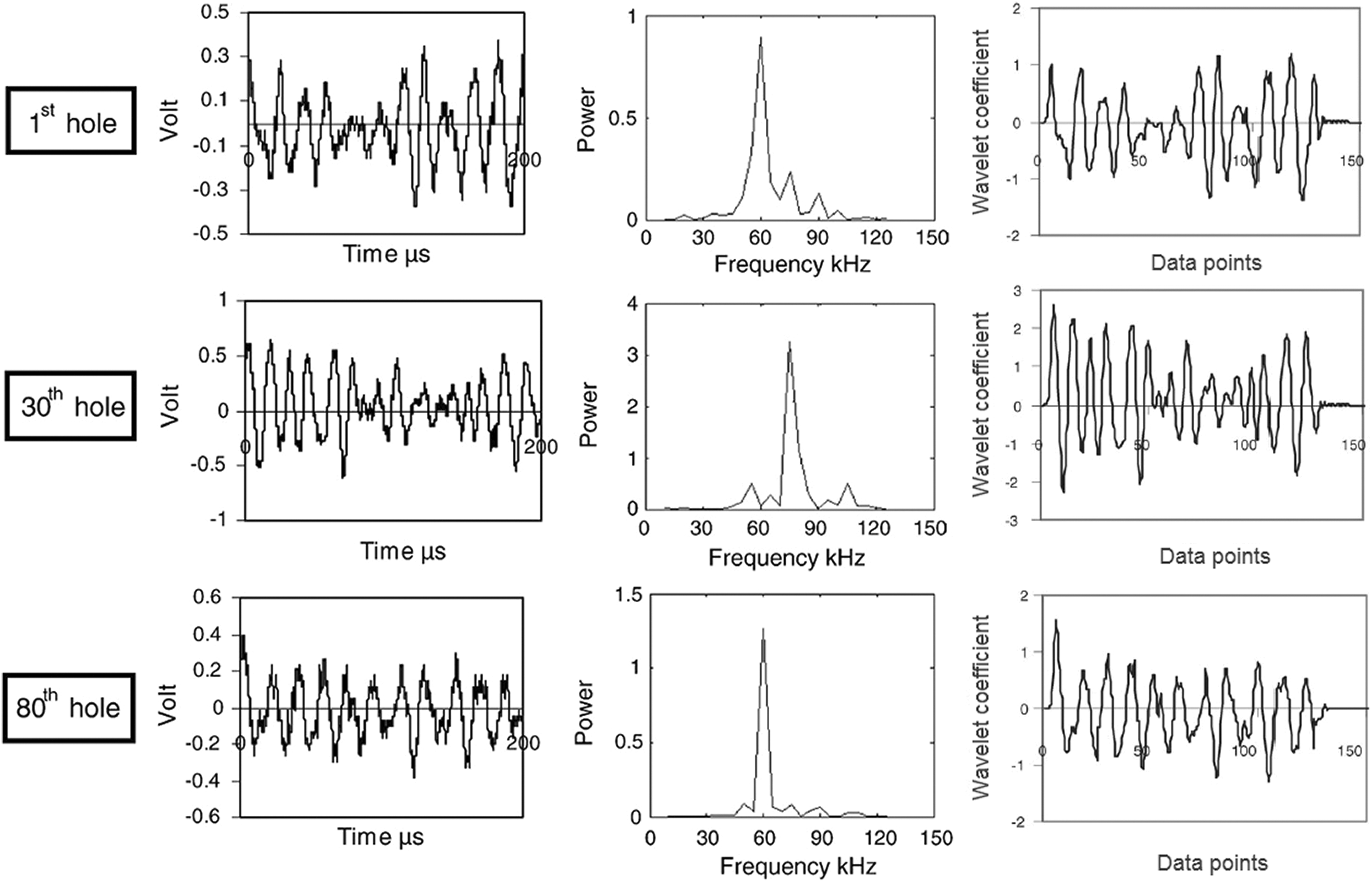
Raw waveforms, power spectrum, and wavelet coefficient of AE signals during drilling of different number of holes in FRCs. 154
The experimental results on delamination damage showed that delamination has a close relationship with thrust force and AE energy as shown in Figure 16. Accordingly, the level of delamination can also be predicted by the number of AE pulses passes further than the threshold value (shown by a red line in Figure 16). Comparing the damage-free hole with the two holes with different extent of delamination damages in Figure 16, it is confirmed that the hole with more severe delaminations makes more peak feature pulses in the AE rms signal. 129 Considering the fact that tool life can be predicted by thrust force, the AE signal can also be used for tool life prediction. Therefore, monitoring of delamination status and tool wear is possible by using AE sensor to improve the efficiency of drilling composite materials as well as save costs.
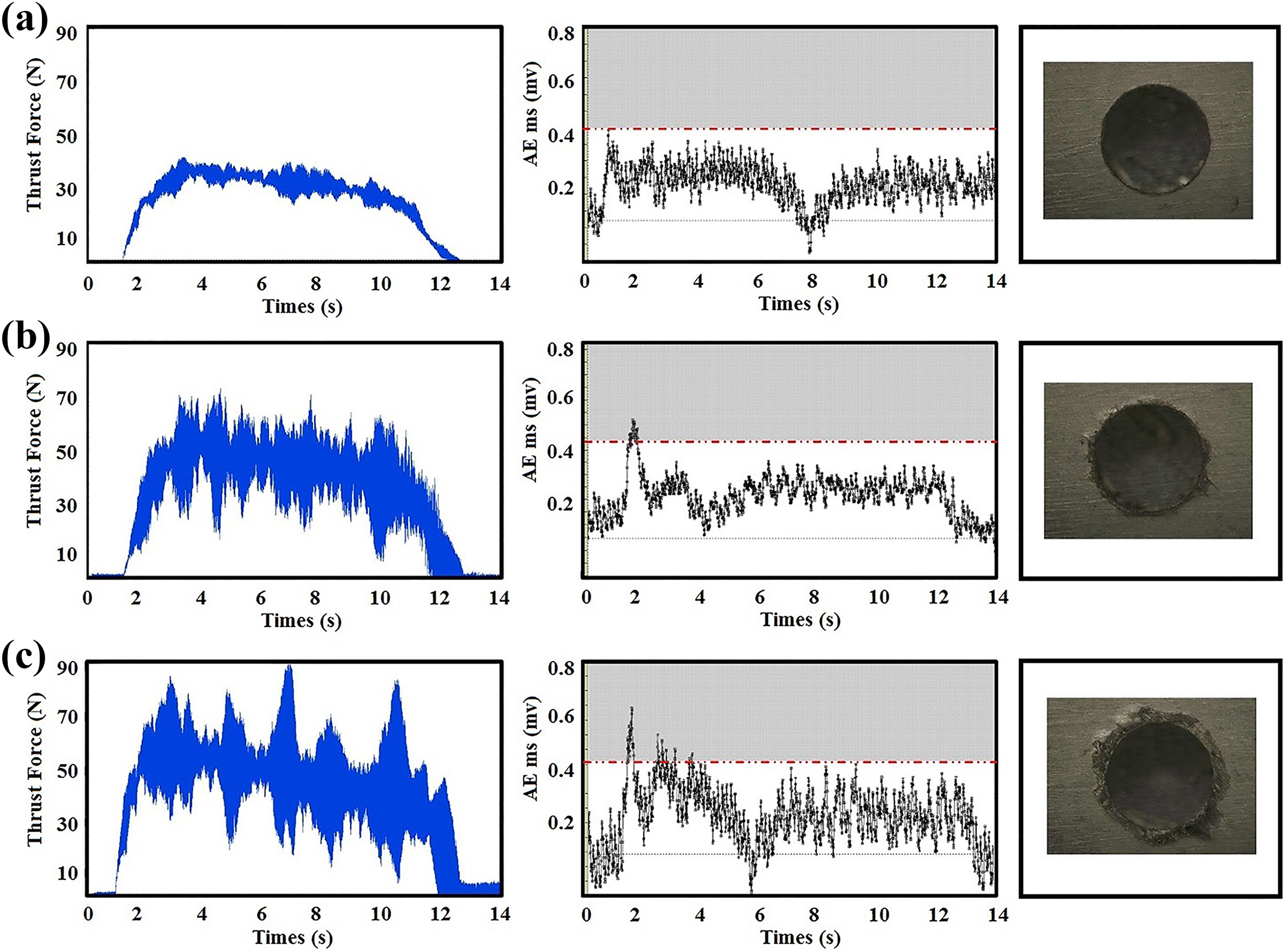
Comparing three holes by delamination, thrust force, and AE rms: (a) damage-free hole with no delamination (b) hole with delamination damages, and (c) hole with serious delamination damages. 129
Conclusions
The outstanding mechanical and physical properties of natural fibers such as high strength-to-weight, high stiffness-to-weight, low density, good thermal insulation, and biodegradability have encouraged the use of these materials to replace petroleum-based and nonrenewable resources in reinforcing composite materials.
There is a wide range of natural fibers available worldwide from both animal and plant origins. Selection of natural fiber for NFRCs strongly relies on the desired properties of the composites as specified by their application. These green composites have found several industrial applications including load bearing and outdoor applications such as automotive exterior parts, sports equipment, transportation facilities, and marine structures, although some limitations occur regarding mainly moisture absorption, variability, and dimensional stability.
During the fabrication process of composites, the process parameters determine the characteristics of the composite and which in turn has an impact on the machinability. The type of fiber can lead to large functional differences that affect the performance of the composite directly, as well as cost. Based on the matrix type, material, shape, size, and desired properties of the final composites, there are several manufacturing methods such as hand layup, CM, RTM, and AFP suitable for fabricating a wide range of NFRCs.
The machinability of NFRCs is affected not only by machining parameters such as feed rate, cutting speed, tool type, and tool size, but also by the physical and mechanical properties of the fibers, as well as by their volume fraction, orientation, aspect ratio, and dispersion in the composites. The delamination, fiber pullout, debonding, tool wear, and the sticking of synthetic resins are the main issues in the machining of NFRCs.
In drilling of NFRCs, conventional mechanical drilling is found to be the most convenient and cost-effective approach to drill holes compared to other drilling processes. VAD and USD have lesser thrust force and lesser delamination damage, and hence generate better results compared to conventional mechanical drilling, which indicates that both methods are more suitable for drilling of NFRCs.
Thrust force and torque are the two main parameters responsible for delamination during drilling of NFRCs but so far there is no well-accepted mathematical model considering thrust force, torque, and cutting parameters simultaneously or a comprehensive literature wherein thrust force and torque are controlled at the same time during drilling. In common, thrust force increases with an increase in the feed rate, and drill diameter, and decreases with an increase in the spindle speed. The torque also exhibits the same trend as thrust force. Controlling both thrust force and torque would be a considerable contribution toward damage-free drilling of NFRCs.
A relationship exists between cutting variables (thrust and cutting forces), tool wear, and the final quality of the drilled hole. Accordingly, the quality of drilled holes can be improved by in-process monitoring in order to record the whole process status through the measurement of thrust force, torque, power, and other indicators. AE sensors as the most practical and intelligent indicators can be used to record the high-frequency waves emanating from damage sources such as matrix deformation, fiber cutting, tool wear, and delamination in order to monitor the process.