
Abstract
Continuous measurement of cardio-respiratory signals offers various kinds of information valuable for the diagnosis of disease and management of the disease process. The article reports the development of the Piezofilm yarn sensor for healthcare applications, and investigates its performance by monitoring cardio-respiratory signals of human body over an extended period of time. Piezofilm yarn sensor was developed by embedding the thin PVDF strips within the textile yarn. The working mechanism of the Piezofilm yarn sensor is based on voltage generation due to the applied stress. In order to deploy the Piezofilm yarn sensor in the application environment, it was integrated into the knitted textile fabric and then sewn to form belt to be placed at the chest wall and wrist area. The raw signals were acquired through the Piezofilm lab amplifier, National Instrument data acquisition device and SignalExpress software. Fast Fourier Transform analysis was performed to calculate the average cardio-respiratory signal frequencies. Based on Fast Fourier Transform analysis, an additional signal-processing step was added to eliminate the unwanted mechanical interference and body signals by using an Infinite Impulse Response band pass filter. The Piezofilm yarn sensor embedded sensing fabric was able to measure both respiratory rate and heart beat rate under static and dynamic conditions. The wrist area measurements for heart beat signals were found to be more uniform in comparison to the chest area measurements. Apart from the general healthcare, this sensing fabric could also be used in studies related to biorhythms, sports, detection of sleep apnea and heart problems.
Keywords
Introduction
In recent years, growing body of work related to wearable health monitoring systems has been reported [1–3] Such systems are intended to use in non-clinical environment and could improve the quality of patient life and reduce the cost of hospitalisation by detecting and preventing the major diseases at early stage. The technology of electronics textile has been in the forefront in the development of such systems. Initial attempts were made by attaching or inserting the rigid sensor components into textiles in order to create textile-based sensing structures [4]. Thereafter, efforts have been focused on producing textile materials with sensing capabilities, instead of using external sensing components. Textile-based structures seem to be good candidates for this aim, thanks to their enhanced comfort and flexibility in comparison to the rigid electronic systems. Textile sensing structures can be developed at various levels of textile manufacturing methods. Hence, sensors can be integrated into textiles at different levels of textile products for health informatics purpose (acquisition, transmission, processing, storing and analysing of health information). The first level covers the fibres [5, 6]; the second level deals with the yarns [7–10] which are manufactured from fibres and the third level is the fabric structures [11–15] which are manufactured through various kinds of fabric forming process such as knitting, weaving, non-woven and braiding. Some successful prototypes have been developed during the last decade for measuring human physiological parameters such as skin temperature [13, 16], heart rate [17], breathing rate[18], ECG [19] and blood pressure [20]. Among these measurements, cardio-respiratory monitoring is an important area in health informatics as respiration and heart beat patterns give valuable information about the general health and condition of patient. Any abnormality in the cardio-respiratory signals can be a sign of some illnesses such as panic attacks, anxiety, asthma, chronic obstructive pulmonary disease, anaemia or heart failure [21].
Generally, textile-based sensing structures have been designed to convert the mechanical stimuli into a measurable electrical signal. The widely used sensing principles in electronic textiles are inductive [22], capacitive [23], piezoresistive [24] and piezoelectric [25] principles. Piezoelectricity is defined as the generation of electrical polarisation in a material by applying mechanical stress to that material [26]. This effect can be observed in many materials ranging from natural materials (quartz, tourmaline, bone, silk, dentin, etc.) to man-made materials (crystals, ceramics, polymers, etc.) [27–29]. Among the piezoelectric materials, polyvinylidene fluoride (PVDF) is the most suitable polymer material to interact with textiles considering its effective electrical output and flexibility [30]. Integration of piezofilm into the textile structures is becoming a considerably more widespread, thanks to their textile-like character and good electric properties [30–33]. The strain or pressure sensing capability of the piezoelectric PVDF material and the absence of the requirement for an external power supply introduce many advantages of its usage in many areas of daily life.
One of the distinctive properties of piezofilm is its high sensitivity to dynamic strain, especially in the range of 10 to 15 mv per microstrain for 28 µm thickness. Some qualifications, such as durability, shock resistance, withstanding millions of flexing cycles, biocompatibility and functionality in harsh and biological environments, make piezofilm a perfect candidate for vital signs monitoring such as heart beat rate and respiration rate [34]. Some examples of the applications are documented in various studies [25, 30, 32, 35, 36].
In addition to its sensing properties, the piezoelectric material can also be used as an energy source by collecting the generated signal [37]. Piezofilm can be utilised in many clothing applications as an energy generator since human body movements represent a perfect source of mechanical energy.
Numerous research efforts towards the integration of piezoelectric property into textiles have been reported as discussed above. However, no attention has been paid towards the use of encapsulation technique for the creation of piezofilm-embedded textile yarns. The literature review has demonstrated that the sensing textile products were mainly developed through weaving, knitting, embroidery, sewing, coating and printing technologies or their combinations [2, 38, 39].
This paper investigates the performance of the sensing fabric (made out of PVDF film based textile yarn) in the real working environment, i.e. measurement of the heart beat and respiration rate of a human subject. A novel fabrication method was used to create the Pizeoelectric Yarn Sensor (PYS) with sensing properties and good textile character. The sensing yarn was utilized then to develop a knitted Piezoelectric Yarn Sensing Fabric (PYSF) on a flat-bed knitting machine. This paper also provides information for preparation of sensor sheets, preparation of PYSF belt and cuff for cardio-respiratory monitoring and the experimental set-up. Thereafter, detailed information is provided for the assessment of the output signals. Digital filtering techniques have been applied in order to extract usable signal from the acquired data and to calculate the average heart beat and respiration rates.
Materials and methods
Measurement of heart rate
The studies related to heart rate monitoring by using piezofilm have demonstrated that respiratory movements affect the quality of acquired heart rate signals. Hence it is important to filter heart beat signal properly without any loss of the desired heart beat signal. According to Sharma et al., most of the physiological phenomenon occur at 1–3 Hz equivalent to 72–180 beats per minute [33]. For filtering breathing signal and other noises, 1 Hz (lower) and 10 Hz (upper) filters can be applied in order to extract real-time signals [34]. Applied band pass filter between 0.8 Hz and 2 Hz covers a physiological range of heart [40] and again a band pass filter between 0.1 Hz and 0.5 Hz covers a physiological respiratory rate [41].
In preliminary testing, it was found that the size of peizofilm could affect the cardio-respiratory measurements. In order to analyze this effect, 30 mm long piezofilm sheets were prepared in three different widths, i.e. 1 mm, 6 mm and 12 mm.
Piezofilm strips of 1 mm were integrated with textile yarn through an encapsulation technique in order to make the PYS. The signals generated out of the PYS were transferred to the data acquisition board through conductive yarns. Later on, these developed PYS were knitted along with the textile yarn in order to create the PYSF. The sensing fabric was cut and stitched to make belt for the chest and wrist areas. The experiments were performed on human body by using both raw piezofilm sheets and the PYSF fabric belt (made out of PVDF based textile yarn). Finally, the PYSF belt and cuff performance were compared with PVDF sheets.
Preparation of samples
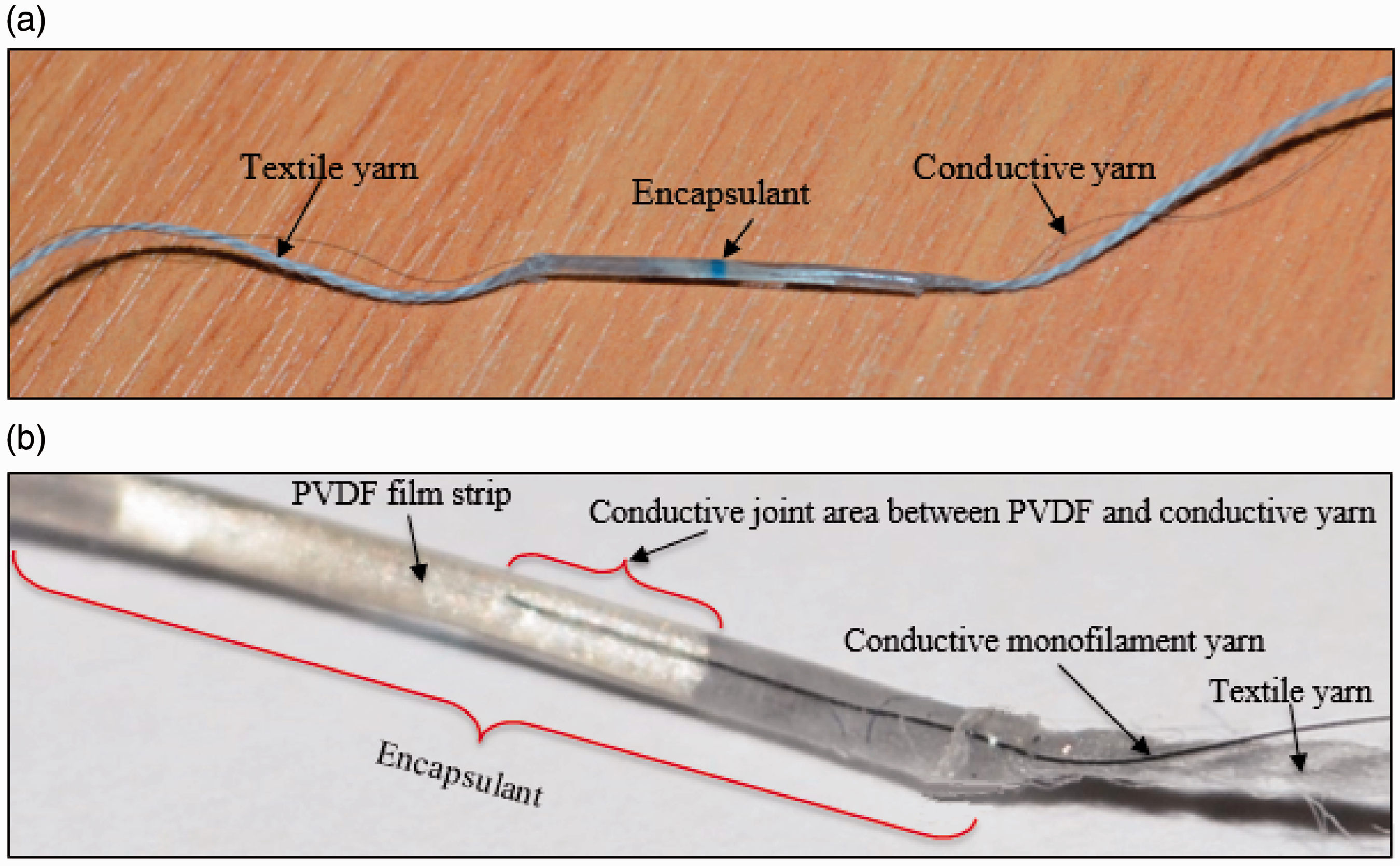
PYSs were prepared by encapsulating piezofilm strips (1–1.5 mm × 10 mm sized) into textile yarns. Initially, a conductive monofilament (carbon coated nylon 6.6) yarn was attached to piezofilm strips in order to create conductive pathways to carry the signal generated. Cyanoacrylate adhesive and silver paint were utilised for creation of conductive joints. This semiproduct was placed into a Polytetrafluoroethylene (PTFE) tube (1 mm inner diameter) with textile yarns and the tube was filled with Dymax-GA-140-LV UV/VIS Gasket polymer as an encapsulant. Thereafter, the resin was cured for 15 s by using Dymax Blue Wave 50 UV curing equipment. In the end, Teflon tube was removed carefully by leaving all sensor areas encapsulated in the resin. In Figures 1 and 2, a schematic view and photographic images of the developed PYSs are presented, respectively.
Conceptual illustration of design of piezofilm yarn sensor. Photopgrahic images of (a) a piezofilm yarn sensor and (b) a closer view of encapsulated area.
The knitted fabric (PYSF) made out of PYSs should meet some requirements such as good skin contact and minimum dislocation of sensing unit within the structure in order to have an accurate result. To achieve this aim, PYSF samples were developed by selecting the knit design with reduced stretch. This would provide the dimensional stability and help the sensing part to retain its location within the structure during the measurements.
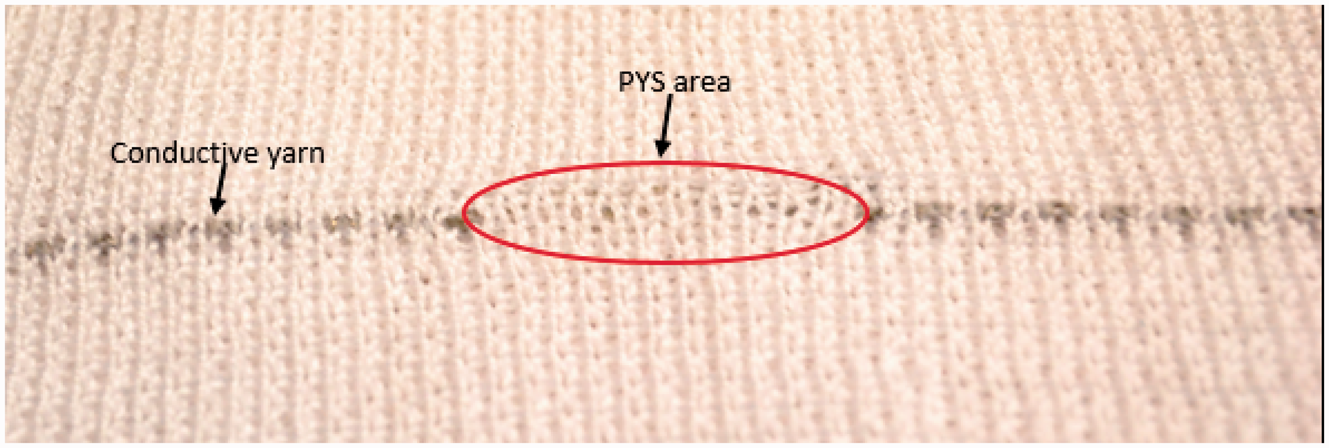
PYS samples were knitted along with acrylic yarn on a manual flat bed knitting machine. It should be noted here that while acrylic yarn was knitted in normal stitch arrangement, the sensing part of PYS was knitted as a float stitch to prevent damage which may be occurred by the needle. The knitted fabric has five courses and six wales per centimetre. Base fabric was knitted as a full milano arrangement as seen in Figure 3. This knitted structure has a relatively higher dimensional stability and less stretchability. This would help to avoid the dampening of the force resulting in less voltage output. An image of the full Milano knitted fabric with the inclusion of the single PYS is shown in Figure 4. Finally, Velcro pads were sewn on base fabric to fasten the PYSF belt.
Needle notation of piezofilm yarn sensing fabric based on Milano knitting arrangement. Photograph of piezofilm yarn sensing fabric showing the floated PYS in the middle of the knitted structure.
Experimental set-up
Test rig set-up
A piezofilm is also a capacitive sensor and therefore the generated charge leaks through the dielectric itself or into the experimental circuitry. The Piezofilm Lab Amplifier is developed by Measurement Specialties for controlling this charge leakage in a suitable way for the application. The amplifier has two modes i.e. charge mode and voltage mode. In the charge mode, the generated charge flows into the circuit components then to a feedback capacitor removing all charge from the sensor. The charge mode feedback capacitor has a range of 100 pF–100nF. By selecting a higher feedback capacitor, the overall gain of sensor output will be decreased; however, selecting a lower value will produce additional sensor gain. In the voltage mode, all charge stays on the sensor and the input signal behaves as though it has been presented with extremely high impedance. In this mode, the impedance seen from the input terminals should be maintained at infinite value. In this case, the input terminal of the measurement device shows an open circuit characteristic. Virtually, no charge generated by the sensor is sunk in the measurement device. Accordingly, the voltage drop across the cable becomes almost zero. This allows accurate voltage sensing which is free from cable impedance variations. Virtually this extremely high input impedance can be practiced by means of operational amplifiers (op amps). As seen from Figure 5, input voltages at positive and negative terminals are equal and the current drawn by them is zero. For a stable circuit, a bleed resistor is required on the input. This mode is used if the lab amplifier will be changed by a simple buffer stage or an “End of cable” output voltage is preferred. In the voltage mode, the input impedance can be adjusted from 1 G (50PF) to 1 M (50PF). This property helps to change the electrical resistance at the input of the amplifier. During experiments, a visible signal could only be gotten when this control was set to 1 M. Gain control on the amplifier ranges between 0 and 40 dB, and 40 dB will provide a linear gain of 100× which helped to capture heartsignals.
Schematic drawing of an operational amplifier.
A piezofilm lab amplifier, National Instruments (NI) data acquisition device and NI SignalExpress software were used to acquire the output signals from the human body through the sensing part. Two-step signal filtering was applied for noise reduction. An initial filtering step was applied by pieozfilm lab amplifier before having the measurements, and the settings were adjusted in the 0.1—10 Hz frequency range by applying the bandwidth filter. Also, measurements were performed on voltage mode with 40 dB gain and 1 M impedance. Figure 6 depicts the schematic diagram of experimental measurement set-up.
Experimental set-up to monitor the cardio-respiratory signals of human body generated by the PYSF.
First, a FFT method was used to find the average respiration and heart beat frequencies and then infinite impulse response (IIR) band pass filters were used to eliminate interference from the breathing and heart beat signals.
Tests with duration of 60 s have been performed in steady and dynamic states while the subject was sitting, walking and standing. Sensor belt and cuff were placed on the chest and wrist areas, respectively.
Results and discussion
Test results for PVDF sheets (chest area)
All experiments were performed in voltage mode. However, for investigation purposes, the charge mode was also used for comparison. Before the start of the test, the amplifier settings were adjusted (1–10 Hz frequency range, 40 dB gain for the measurement of heart and respiration rate).
The experiments were carried out by placing piezofilm strips onto the chest area with the help of a double-sided tape. In order to see the heart beat amplitude clearly, the subject was instructed to hold his breath for an extended period of time (30 s). When the chest is in the expanded position filled with air, the heart signals tend to be in high amplitude with reduced noise. This experiment, which was done by holding breath, does not include the measurement of the breathing rate. Experiments were also performed at sitting position with normal breathing pattern. Figure 7 shows the effect of different amplifier settings on the measurement of heart beat signal.
Cardio-respiratory measurements at different amplifier settings: (a) charge mode, holding breath; (b) charge mode, breathing; (c) voltage mode, holding breath and (d) voltage mode, normal breathing.
It can be observed from Figure 7 that the results obtained in voltage mode with normal breathing condition have an advantage that the heart beat signal can easily be distinguished from breathing signal. Hence, this setting was employed for the rest of experimental measurements in this study.
Figure 8 shows results of cardio-respiratory signals obtained from 30 mm long PVDF sheet strips of different widths, i.e. 1 mm, 6 mm and 12 mm. It can be observed from the graphs that PVDF sheets of any given size were able to record cardio-respiratory signals. However, some unwanted interference signals from human body and environment were also noticed. Thus, an additional signal-processing step was added to eliminate the interference from the cardio-respiratory signals. Firstly, a Fast Fourier Transform (FFT) method was used to find the average respiration and heart beat frequencies and then an IIR band pass filter was used to eliminate interference from the breathing and heart beat signals.
Cardio-respiratory signals obtained from PVDF sheets (Chest area). *Heart beat rate (HBR), respiration rate (RR).
As it is clearly seen from Figure 9, there is a positive correlation between PVDF sheet size and voltage output, i.e. the bigger size PVDF film produced the stronger output signals.
Relationship of piezofilm size (width) to its full scale voltage output.
In this case, R2 value of 1 indicates perfect fitting of regression line to the data. This means that the R2 value of the voltage–force curve shows how good voltage output value is for predicting the applied force stimuli.

Also, it should be noted that the magnitude of the breathing signal is not only higher than the heart beat signal but its signal output pattern is also more uniform than the heart beat output. The reason behind this observation is that the pressure of the torso during the respiration is much higher than the vibrations of the chest area created by beating of heart.
Test results for PYS Fabric (PYSF) on chest area
Figures 10 and 11 show the results of cardio-respiratory signals which were acquired from a PYSF belt in sitting position. In this arrangement, two samples of PYS were used along with the textile yarn to construct the PYSF belt in order to get sufficient output signals. As evident from the graphs of Figures 10 and 11, the PYSF belt was able to acquire both signals sufficiently. However, the breathing signal output pattern is more uniform in comparison to the heart beat and the magnitude of the respiration signal is higher than the heart beat signal, similarly to the PVDF sheet measurements. Another test was also performed when the subject was walking. The subject wore the belt that was connected to the set-up. Hence, walking action was performed without moving forward for 60 s. Heart beat signals were successfully obtained in this case. Respiratory signals could not be acquired properly due to the motion artefacts of the human body during the walking action. However, it is still possible to observe respiration due to increased amplitude of the heart beat signal at inhaled state as seen in Figure 11(b). The FFT analysis was performed to find the average heart beat rate while the digital signal filtering was applied in order to remove unwanted interference from the heart beat signal.
Close view of cardio-respiratory measurement results from chest area in sitting position: (a) PYSF and (b) 1 mm piezofilm strip. PYSF belt cardio-respiratory signal measurements (a) during sitting (b) during walking.

Test results for PVDF strip and PYSF cuff (wrist area)
Cardio-respiratory signals were successfully taken from chest area as discussed in the previous section. Now the wrist experiments will be explained. Because of the location of the wrist, it was not possible to get the respiration signals; therefore, only heart beat signals were acquired. Figures 12 and 13 show the results obtained from the wrist area measurements. It can be observed in the graphs that the heart beat signals are clearer and selectable in comparison to the measurements taken from the chest area. In previous tests, respiration signal was dominant to heart beat signal. In this case, PYSF cuff measurement performance was comparable to PVDF film strip performance. However, signal magnitude of PYSF cuff is found to be slightly lower than PVDF film strip due to reduced contact to human skin compared to PVDF film strip.
Close views of pulse measurement results for comparison: (a) PYSF and (b) 1 mm piezofilm strip. Comparison of PYSF and piezofilm during heart beat rate measurement at wrist position.

Conclusion
A PYS has been developed by embedding the piezoelectric PVDF strip within the textile structure. A knitted sensing fabric made out of the PYS was deployed to monitor the cardio-respiratory signals in the non-clinical environment. The working mechanism of the PYS is based on the voltage production of the PVDF strips due to the applied stress. This principle was exploited to capture the impacts or vibrations generated by the respiratory efforts and the heart. FFT analysis and digital filtering techniques (IRR bandpass) were applied to get the useful breathing and heartbeat signals out of the raw data.
The sensing fabric was able to measure both respiratory rate and heart beat rate under static and dynamic conditions, e.g. in sitting position 1.47 Hz and 0.2 Hz for heartbeat rate and respiration rate frequencies, respectively. When the subject wore the PYSF, only heart beat signal was obtained during walking action. Respiration signal was lost due to motion artefacts. However, this problem could be eliminated by changing elasticity and tightness of the belt. Wrist area measurements for heart beat signals gave more uniform signals in terms of average signal amplitude compared with the chest area. In addition, absence of breathing interference prevented heart beat signal amplitude expanding and contracting. Also, it should be noted that the magnitude of the breathing signal is not only higher than the heart beat signal but its signal output pattern is also more uniform than the heart beat output. The reason behind this observation is that the pressure of the torso during the respiration is much higher than the vibrations of the chest area created by beating of heart (Chest wall test).
The integration procedure of the PVDF into the fabric has resulted in slight decrease in the signal amplitude compared with 1 mm piezofilm strip. However, knitted sensor measured the bio-signals successfully.
It can be concluded that the PYSF could be used to monitor the cardio-respiratory signals in the static and dynamic environment, and this is a promising work to be improved in the future for use in daily life for health monitoring or sports applications.
Footnotes
Declaration of Conflicting Interests
The author(s) declared no potential conflicts of interest with respect to the research, authorship, and/or publication of this article.
Funding
The author(s) received no financial support for the research, authorship, and/or publication of this article.