
Abstract
The electromagnetic shielding effectiveness (EMSE) of herringbone, whipcord, barathea, and crêpe woven fabrics, which are twill and sateen derivatives, woven with textured steel yarns has not been investigated so far. Therefore, in this research, textured stainless steel yarn, which has soft feeling and flexibility, required properties for clothing fabrics, was selected as a conductive yarn to produce conductive fabrics whose weaves are twill, twill and sateen derivatives. The EMSE of these common clothing fabrics woven with different conductive yarn densities were measured by free space measurement technique with different antenna polarizations, because of the possibility to obtain measurements for a large bandwidth. It was observed that all conductive clothing woven fabric samples shielded well in medium and high frequency bands, which contain 900 MHz GSM, 1800 MHz GSM, 2100 MHz 3G, and 2400 MHz Wi-Fi bands. Most of the samples give acceptable EMSE values up to 40 dB at certain frequencies. The EMSE of fabric samples would remain almost the same, although conductive yarn density changed, because of diagonally or symmetrically arranged conductive yarn floats in fabric structures. The EMSE characteristics of different weave types are investigated and it is seen that when the yarn floats arrangement is changed the EMSE characteristic changes. And also, it is observed that measurements of fabrics, positioned so that the weft yarns were parallel to the antenna polarization are similar to those of fabrics, positioned so that the weft yarns were vertical to the antenna polarization.
Keywords
Introduction
Electromagnetic (EM) pollution has become a part of human life since the first quarter of the 20th century. Electrical and EM energy has found wide application areas with the developments in technology. Although the electrical and electronic devices which we use in our daily life make our life easier, they create EM pollution problem which is really a serious problem. In this regard, EM fields have possible effects on human health. So, it is important to create public concern about the exposure to these EM fields. Nowadays, a definition called “electrosmog” is created to define EM pollution. The expectations from textile materials change and vary with the changing life styles and the new concepts brought by the new life styles including shielding for EM fields [1].
EM field is a concept to explain the effect of charge particles to each other and direction of this effect, which is created around the charges, changes with characteristics of charges, distance from the charges, and motions of charges. EM fields consist of electric and magnetic fields. There exist many human-made EM field sources around us, such as cathode ray tube (CRT) television, cell phones, radars, computers, home appliances, transmitters, base stations, and magnetic resonance imaging. In literature, the magnetic field is found to have more effects on human health [2]. It is though that for higher frequencies, electric field has more effect. Because of this, it may be desired to shield electric and magnetic field together or separately depending on the application. EM spectrum, which includes radio, microwave, infra-red, visible light, ultraviolet, x-ray and gamma-ray frequencies, spreads between frequencies of MHz (106 Hz) and EHz (Exa Hz or 1018 Hz). The microwave frequencies cover 300 MHz to 300 GHz which correspond to the wavelengths of 1 m and 1 mm, respectively. The microwave frequency spectrum is divided into several bands. The ultra high frequency band has a frequency range of 300–3000 MHz which includes many commercial bands such as 900 MHz GSM, 1800 MHz GSM, 2100 MHz 3G, and 2400 MHz Wi-Fi. Since many electronic consumer products operate at those frequencies, shielding of EM fields of these specific frequencies are quite attractive [3].
Shield is a barrier used for preventing EM fields to diffuse into the media of interest. Materials which have the ability of EM screening are commonly used to reduce the power of EM fields. The performance of a screen is defined with shielding effectiveness (SE) value. The results of SE measurements depend on the measurement method, frequency range, sample dimensions, and the characteristic of the material [4].
Recently, conductive textile materials, which are lightweight, flexible, and non-expensive, have been commonly used in many applications instead of metal screens: Perumalraj et al. [5] selected copper as a conductive filler to produce copper core yarns with cotton fiber as sheath material to make plain and twill woven fabrics, and measured the EM shielding effectiveness (EMSE) of these fabrics in the frequency range of 20–18,000 MHz with coaxial transmission equipment. They observed an increase in SE with an increase in the number of conductive fabric layers, finer yarn count, warp density, weft density, cover factors, and a decrease in SE with copper wire diameter. Roh et al. [6] used metal composite yarns, which were used in the construction of plain woven metal composite fabrics, were produced with commercially available metal filaments and polyester (PET) filaments. Plane-wave shielding properties of the composite fabrics were measured between 30 and 1500 MHz using the coaxial transmission-line method. They observed that while the overall EM SE increased with metal content, different frequency dependence related to the aspect ratio of metal grid structure.
Özdemir and Özkurt [7,8] measured the EMSE of some cellular and diced woven conductive fabrics woven with stainless steel core yarns at different weft densities by free space measurement technique at horizontal polarization of the antenna. They observed that woven fabric samples, which were positioned so that the weft yarns were parallel to the antenna polarization, shown good EM shielding performances in high frequency band, namely industrial, scientific and medical (ISM) band. They also observed that the EMSE of woven fabric samples increased in accordance with the steel core yarn density in high frequency band if the fabric samples were positioned so that the weft yarns were vertical to the antenna polarization. When the effective surface conductivity increased, the decrease in the EMSE of woven fabric samples, which were positioned so that the weft yarns were parallel to the antenna polarization, was observed, adversely.
Su and Chern [9] selected stainless steel as the conductive filler to produce stainless steel hybrid yams to make plain and twill woven fabrics. The EMSE of these fabrics was measured by coaxial transmission equipment in the frequencies range from 9 KHz to 3 GHz. The experimental results showed that denser structures of stainless steel fabrics had a higher EMSE. The fabric made from the core yarns had a higher EMSE than that made from the cover yams and the plied yams. Analyses of the weave types reveal that the plain weave had a higher EMSE than twill weaves. Cheng et al. [10] produced twill copper fabrics (3/1) and obtained their EMSE using a coaxial transmission line holder in the frequency range of 144–3000 MHz. They observed that with an increase in the number of conductive fabric layers, warp density, and weft density, an increase in SE occurred, whereas with an increase in wire diameter, a decrease in SE occurred.
Chen et al. [11] measured plane-wave shielding properties of 2/2 twill woven fabrics and laminated composites at 30–1500 MHz using the coaxial transmission-line method. Copper wire and polyamide filaments used as core yarn were wrapped with polypropylene filaments. They found that the SE of a single layer was barely satisfactory for general applications and the multi-layer fabrics provide adequate plane-wave SE (20–55 dB) when the wave was normally incident and laminate thickness was >1.6 mm. Duran and Kadoğlu [12] investigated the shielding characteristics of 3/1 twill woven fabrics produced with cupper core yarns. They found that weft density, thickness of the copper filament in the core, and frequency were significant factors for achieving the EMSE.
Varnaitė et al. [13] wove plain fabrics with only polyethersulfone (PES) warps. Conductive yarns were inserted in the fabrics in three different variants: 1) 25 picks PES + 1 pick PES/INOX; 2) 49 picks PES + 1 pick PES/INOX; 3) 71 picks PES + 1 pick PES/INOX. The fabric with only the PES picks was used as control fabric. It was found that the bigger quantity of conductive weft yarns increased values of the shielding factor. And also shorter half decay time resulted in increase of shielding factor. Sandrolini and Reggiani [14] tested the five electrically conductive woven and non-woven fabrics by circular coaxial transmission line holder in the frequency range 300 kHz–3.6 GHz. The results showed that a low surface resistivity value was a requirement for a higher SE especially for woven materials. The nickel amount used for the metallization did not have such a strong relation with the SE, as the geometry of the warp and weft of the textile played an important role in the shielding performance, too.
Palamutçu et al. [15] developed an EM shielding efficiency (SE) measurement set and tested its reliability within the circumstance of the produced electrical conductive plain knitted and plain woven fabrics. In these fabrics, Co/Cu and Co/Cu/Ag yarns with different ratios were used. For woven specimens at the 860–960 MHz frequency range, the highest level of average EMSE value was found belong to the specimen, which had the lowest level (finest conductive fiber) of conductive fiber content. It was also observed that the highest attenuation was obtained at 1790 MHz with the woven specimen, which had the finest conductive fiber. Joyner et al. [16] examined protective suit consisting of an overall with an integral hood, gloves, and oversocks, constructed of an electrically conductive fabric, theoretically and experimentally for EMSE at radiofrequencies (RFs) in the range from 200 kHz to 4 GHz. They found that at microwave frequencies, the fabrics were certainly capable of providing SE of greater than 20 dB. However, a suit might have a lower SE due to openings and zippers. In order to achieve 20 dB SE to low-impedance low frequency (<30 MHz) fields the fabrics would have to be considerably more conductive. Więckowski and Janukiewicz [17] discussed about the scope of application of the measurement methods of EMSE of textiles, their limitations, and the possibilities for comparisons of the results. They noted that there is currently no effective method for comparing the results of SE measurement obtained based on MIL-STD 285 & IEEE-STD-299 for comparison to ASTM D4935.
The 2/2 twill, 3/1 twill, herringbone and whipcord, which are twill derivatives, barathea and crêpe, which are sateen derivatives, are common weaves used for clothing fabrics [18]. The studies in the literature focused on EMSE of twill and sateen fabrics woven with core conductive yarns in low and medium frequency bands. The aim of the study is to investigate the EM SE of some common clothing fabrics, whose weaves were 2/2 twill, 3/1 twill, herringbone, whipcord, barathea, and crêpe, in large band width. The other aim of this study is to seek for the usability of these clothing fabrics, which were woven with textured steel yarns, inserted in certain intervals, as EM shielding material for GSM, 3 G and Wi-Fi, radiophone and baby monitors. And also the effect of conductive weft yarn density on the EM SE of fabric samples was searched.
Theoretical
EM shielding
Shielding is a term that explains the protection from the unwanted signals by using any material and method which decreases the signal penetration in the media interested. In shielding methodology, the signal strength in the media depends on several parameters related to material properties such as electric and magnetic behavior, conductance on the surface and in the volume, material thickness, and of course system material can be seen in Figure 1, where: Wave transmission on a thin layer of media [17].

The two power densities in this ratio are the measured powers before and after the shield are placed, respectively. The angle of incident wave to the media under test is known as polarization. In regular wave propagation tests, vertically and horizontally directed (polarized) waves are used in measurements shown in Figure 5. By changing wave direction, the behavior of material under test can be tested for changing conditions of polarization depending on material internal structure. The polarization can be changed by antenna rotation physically or manipulation of signal source electrically.
The measurement set-up [22].
Experimental
Production of woven fabric samples
In this research, 24 types of clothing woven fabric samples (42 × 42 cm) were produced in weaving workshop of in-house by CCI automatic sample rapier loom (Evergreen 8900, Taiwan). The 100% PET yarns and textured stainless steel yarns, which have soft feeling and flexibility, required properties for clothing fabrics, were used. The optical image of the textured steel yarn was taken by using Olympus BX 43 Microscopy as shown in Figure 2. The specifications of yarns are given in Table 1. Weave patterns are shown in Figure 3. While the conductive yarns were inserted in certain intervals to obtain different open-grid structures of conductive yarn within the fabrics, which resulted in different conductive weft yarn densities, the conductive and the PET yarns were used in 1 to 4 orders as warp yarns. The characteristics of the conductive fabrics, whose weave interlacing coefficients and average float length of yarns are equal to each other, are shown in Table 2. The open-grid structures of the conductive yarns are represented with gray squares and letter of T, whereas the PET yarns are represented with white squares and letter of P in Figure 4. Both white and gray squares also represent intersection points between warp and weft yarns. Warp and weft settings of 24 kinds of clothing woven fabric samples on the loom were 20 cm−1, which was calculated for the loom state. And also reference samples were woven for all kind of weaves with only 100% PET warp and wefts.
Optical image of textured steel yarn. Weave patterns used in experimental: (a) 2/2 twill, (b) 3/1 twill, (c) herringbone, (d) whipcord, (e) barathea, and (f) crêpe. Schematic diagram of open-grid structures formed in the woven fabrics (gray squares: conductive steel yarns; white squares: polyester yarns). The specifications of yarns. The specifications of conductive fabrics. T represents textured steel yarn, P represents polyester yarn.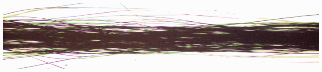


Fabric samples were coded according to their weave pattern, warp, and weft densities as in Table 2. The letter and number in each fabric code represent weave patterns and weft yarn arrangement, respectively. The 2/2 twill, 3/1 twill, barathea and crêpe weaves are square unit weaves, so the number of each warp and weft yarn interlacing is equal to each other, namely the average yarn interlacing is equal to number of yarn interlacing. And also the average float length of warp yarn is equal to the average float length of weft yarn. The average float length F has been calculated according to Ashenhurst [20] by equation (2);


The specifications of herringbone and whipcord woven fabrics.

Measurement of EMSE
In this study, free space measurement technique was used in order to determine SE of woven fabrics. Fundamental measurement method was based on the signal attenuation on two sides of woven fabric material located on far field zones of transmitter and receiver antennas. Far field region for interested frequency band is between 0.3 m and 1 m approximately depending on frequency. Because of that, antennas are placed far away from that distance. Transmitter antenna had horizontal polarization. Woven fabrics behaved as a reflector, absorber, and attenuator on incident field. The ratio of total amount of transmitted signal strength over total incident signal strength determined the SE term related to material properties given above. The measurement set-up and the practical measurement set-up are shown in Figures 5 and 6. A spectrum analyzer, Anritsu MS2711D (Anritsu, Morgan Hill, CA) with the option of transmission measurement was used for the tests. In transmission measurement option, reference level without shielding material under test was taken automatically with normalization process and the signal level with the material was compared in logarithmic scale in terms of RF power.
Practical measurement set-up.
In other words, initially, the reference signal was collected without the shielding material at all frequencies. Afterwards, the woven fabrics were attached on the foam layer which was placed between receiver and transmitter equipments. Finally, the signals obtained from both states were compared. Each fabric sample was measured two times; the fabric sample was positioned in the manner that the warp yarns were firstly vertical to the antenna polarization, in a word vertical measurement, secondly parallel to the antenna polarization, in a word horizontal measurement. The measurements were realized within a band of 800–3000 MHz. In this spectrum, GSM 900, GSM 1800, several ISM bands which can be used for personal purposes in limited power levels such as IEEE811.1 bg band were available. Conductive woven fabrics were investigated for attenuation levels and the frequencies in a wide band.
The received signal may be affected by reflections from surrounding environments such as walls, metal equipments, etc. in each case, with and without material under test, when the equipment cannot overcome that interference conditions. The spectrum analyzer used in these measurements has a capability of transmission mode operation. In this operation, the system calibrates received power for every frequency component in working spectrum, then, the attenuation is stored for each frequency. This option prevents reflection effects by considering with or without material cases, and a relative signal attenuation is stored. By the same interference signal is applied in both cases, the result is more accurate.
Results and discussion
The reference fabric samples woven without conductive yarns have too much low EM SE as shown in Figure 7.
The EMSE of reference fabric samples woven without conductive yarns for vertical measurements: (a) 2/2 twill, (b) 3/1 twill, (c) herringbone, (d) whipcord, (e) barathea, and (f) crêpe.
In Figures 8–13, the one colored graphics show the original signal, whereas the two colored graphics show the average of signal as well as the original signal in order to make signal levels more visible against noise, which is generated by reflections and refractions due to the measurement environment. The average of EMSE values were taken by running average technique by using offline data.
The EMSE of 2/2 twill weave: (a), (c), (e), (g) vertical measurements of fabric samples woven with TP 1:1, TP 1:2, TP 1:4, TP 1:8 weft arrangements, respectively; (b), (d), (f), (h) horizontal measurements of fabric samples woven with TP 1:1, TP 1:2, TP 1:4, TP 1:8 weft arrangements, respectively.
The EMSE of sample A1 has an average value of 8 dB around frequency bands of 1400–3000 MHz which covers the 1800 GSM, 2100 3 G, and 2400 Wi-Fi bands and 5 dB at frequency band of 900 MHz as given in Figure 8. This sample has a very large bandwidth but low EMSE values. As the conductive ratio becomes smaller, the EMSE values of A2, A3, and A4 for vertical and horizontal measurements drop to 5 dB at around 1800 MHz, as expected. This is due to the fact that adjacent conductive weft floats are arranged, in the same way in these samples, by shifting one warp yarn. The horizontal and vertical measurements differ slightly since the warp and weft yarns in 2/2 twill have the same weave interlacing coefficient, namely the same average float length.
It is observed in Figure 9 that the B samples have three bandwidths. The first one is 900–1000 MHz with an average EMSE of 10 dB, the second one is 1600–2000 MHz which has an average EMSE of 9 dB, and the third one is 2200–3000 MHz which has an average EMSE of 12 dB. The EMSE of 3/1 twill is higher than 2/2 twill, this is due to the fact that yarns in 3/1 twill passing over three intersecting yarns run in the diagonal direction, whereas yarns in 2/2 twill passing over two intersecting yarns. The average EMSE values of all B samples around mentioned frequency change insignificantly as the conductive ratio changes, quite the contrary. This is probably because of the fact that in sample B2, B3, and B4 conductive weft yarn floats arranged diagonally by shifting one warp yarn, therefore the strong interaction happened between the conductive weft yarns against EM waves, and this increases the EMSE of B2, B3, and B4. The vertical and horizontal measurements for all B samples do not differ; this is because of the fact that the warp and weft yarns in 3/1 twill are interlaced together by passing over and under each other in the same way.
The EMSE of 3/1 twill weave: (a), (c), (e), (g) vertical measurements of fabric samples woven with TP 1:1, TP 1:2, TP 1:4, TP 1:8 weft arrangements, respectively; (b), (d), (f), (h) horizontal measurements of fabric samples woven with TP 1:1, TP 1:2, TP 1:4, TP 1:8 weft arrangements, respectively.
Samples of herringbone woven fabrics appear to have larger bandwidth yet with low EMSE values as given in Figure 10. The average EMSE value drops to 7 dB but the effective bandwidth can be considered between 900 and 3000 MHz which includes the 900 GSM, 1800 GSM, 2100 3 G, and 2400 Wi-Fi bands. The large bandwidth causes the low EMSE values. The average EMSE values of all C samples around mentioned frequency range are almost similar as the conductive yarn ratio changes. This is probably due to the symmetrical arrangement of the conductive weft yarn floats, thus the conductive weft yarns interact with each other against EM waves, and this increases the conductivity of C2, C3, and C4. The vertical and horizontal measurements are nearly the same for C samples too, since the warp and weft yarns in herringbone weave have the same weave interlacing coefficient, namely the same average float length, the intersection of warp yarns differs from that of weft yarns though.
The EMSE of herringbone weave: (a), (c), (e), (g) vertical measurements of fabric samples woven with TP 1:1, TP 1:2, TP 1:4, TP 1:8 weft arrangements, respectively; (b), (d), (f), (h) horizontal measurements of fabric samples woven with TP 1:1, TP 1:2, TP 1:4, TP 1:8 weft arrangements, respectively.
When D samples’ measurements are investigated in Figure 11, the effective EMSE values are observed around 1600–2000 MHz with an average value of 9 dB and 2100–3000 MHz with an average value of 11 dB. The average EMSE values of D samples do not change significantly, as the conductive ratio reduces. It is probably because of the fact that in D2, D3, and D4, half of the conductive weft yarns passing over two intersecting yarns and arranged diagonally by shifting one warp, whereas other half of the conductive weft yarns have the highest weave interlacing coefficient in whipcord weave, and these increase the EMSE of D2, D3, and D4. Since the conductive weft yarns have two different yarn interlacing coefficients, namely two different average float lengths, whereas the conductive warp yarns have the same weave interlacing coefficient, namely the same average float length, the horizontal measurements differ from vertical measurements.
The EMSE of whipcord weave: (a), (c), (e), (g) vertical measurements of fabric samples woven with TP 1:1, TP 1:2, TP 1:4, TP 1:8 weft arrangements, respectively; (b), (d), (f), (h) horizontal measurements of fabric samples woven with TP 1:1, TP 1:2, TP 1:4, TP 1:8 weft arrangements, respectively.
The E samples in which conductive warp and weft yarn floats are arranged diagonally can also be considered as large bandwidth shielders, since they have average EMSE values between 9 and 12 dB within the frequencies of 1600–3000 MHz as shown in Figure 12. These samples are the most effective ones since they have large bandwidth and moderate EMSE values. The average EMSE values of all E samples around mentioned frequency range are almost similar as the conductive yarn ratio changes. This is probably due to the diagonal arrangement of the conductive weft yarn floats, and this increases the conductivity of E2, E3, and E4. The horizontal and vertical polarized measurements show difference but the efficient frequencies do not change. The reason explained for 2/2 and 3/1 twill woven fabric samples is valid here also.
The EMSE of barathea weave: (a), (c), (e), (g) vertical measurements of fabric samples woven with TP 1:1, TP 1:2, TP 1:4, TP 1:8 weft arrangements, respectively; (b), (d), (f), (h) horizontal measurements of fabric samples woven with TP 1:1, TP 1:2, TP 1:4, TP 1:8 weft arrangements, respectively. The EMSE of crêpe weave: (a), (c), (e), (g) vertical measurements of fabric samples woven with TP 1:1, TP 1:2, TP 1:4, TP 1:8 weft arrangements, respectively; (b), (d), (f), (h) horizontal measurements of fabric samples woven with TP 1:1, TP 1:2, TP 1:4, TP 1:8 weft arrangements, respectively.

The F samples in which conductive warp yarns are arranged diagonally as in the D samples show similar results to D samples. It is seen in Figure 13 that they are most effective between the frequencies of 1600–2000 MHz and 2100–3000 MHz having average EMSE value of 11 dB for both frequency bands. The average EMSE values of all F samples around mentioned frequency range are almost similar as the conductive yarn ratio changes. The reason explained for barathea woven fabric samples is valid here also. The vertical polarized EMSE values are approximately the same with the horizontal polarized EMSE values. The reason explained for 2/2 twill, 3/1 twill, and barathea woven fabric samples is valid here also.
The frequency responses of different grid structures show that, only the specimens woven with highest density of conductive weft yarns give best EMSE performance and as the yarn density are decreased, related EMSE patterns in frequency band stay similar, except for 2/2 twill woven specimens. That can be explained because of resonant frequencies’ wavelengths are very big depending on the yarn sizes, but specimens woven with highest density of conductive weft yarns behave as conductive planes, which have maximum EMSE performance. The frequency response of the EMSE in all samples has band limited manner and those bands are similar for specimens woven with the same weaves.
Since the first samples have highest density of conductive weft yarns and the same characteristics as other samples of the same weaves woven with lower conductive weft yarn densities, it is meaningful to compare the EMSE characteristics of the first samples within them. When the vertical measurements of the samples are investigated, the samples A1 and B1 show the similar EMSE characteristic; however B1 has 1–2 dB EMSE values better than A1. Moreover, C1 has a new EMSE frequency band around 1160 MHz and 10 dB EMSE values, compared to other samples A1, B1, D1, E1, and F1. Furthermore, D1, E1, and F1 have worse EMSE characteristic in the lower frequency bands but F1 has better EMSE values in the upper bands compared to the samples D1 and E1. Also, the horizontal measurements of the samples show the same characteristics as the vertical measurements of the samples.
Conclusions
In this paper EMSE measurement of 2/2 twill, 3/1 twill, herringbone, whipcord, barathea, and crêpe woven fabrics, produced on automatic sample loom with textured steel yarns, were first time investigated. Open-space measurement was preferred because of the possibility to obtain measurements for a large bandwidth. Anritsu MS2711D spectrum analyzer with the option of transmission measurement was used in the measurement for the frequencies between 700 and 3000 MHz which spans the frequency bands of interest.
Most of the samples gave acceptable EMSE values up to 40 dB at certain frequencies. The first samples of 2/2 twill, whipcord and barathea woven fabrics, second samples of whipcord and barathea woven fabrics and all samples of 3/1 twill, herringbone and crêpe woven fabrics show acceptable EMSE characteristic for the frequency bands of 1800 MHz GSM and 2400 MHz Wi-Fi bands, which were between the 10 dB and 25 dB. All samples exhibited better EMSE values, which were bigger than 10 dB, for frequencies above 1800 MHz.
The average float length, the weave interlacing coefficient and the arrangement of yarn floats, which determine the fabric structures and properties, have significant effects on the EMSE performance of clothing fabric samples:
The effective frequencies did not change with the weave pattern, due to their equal average float lengths. Although the average float length of 2/2 twill is equal to that of 3/1 twill, the EMSE values of 3/1 twill woven fabrics, in which yarns pass over three intersecting yarns, were higher than those of 2/2 twill woven fabrics. The 3/1 twill woven fabrics have the best EMSE values at frequency band around the 2400 MHz up to 15 dB. Symmetrical arrangement of yarn floats leaded to enlarge the bandwidth and to decrease the SE of herringbone woven fabrics to 7 dB. The EMSE of crêpe woven fabrics, whose construction is similar to whipcord weave in respect to diagonal arrangement of warp yarn floats. The crêpe woven fabrics in which conductive warp and weft yarn floats are arranged diagonally showed the best EMSE performance at frequency band around the 1800 MHz up to 25 dB.
The 2/2 twill, 3/1 twill, whipcord, barathea, and crêpe woven fabrics show approximately the same EMSE characteristics since their yarn floats are arranged in diagonally. However, in herringbone woven fabrics yarn floats are arranged symmetrical to vertical axis which changes the EMSE characteristic of this weave by adding a new shielded frequency band around 1160 MHz with EMSE value of 10 dB.
When the density of conductive weft yarn decreased in most of the weaves, the EMSE did not change significantly, it is considered that diagonal or symmetrical arrangements of conductive yarn floats, which lead the interactions between the conductive yarns against EM waves, cause to increase the EMSE. Moreover, the vertical and horizontal measurements of woven fabrics were nearly the same, whose average float length and interlacing coefficient of warp yarn are equal to those of weft yarn, namely the squire weave structures. On the other hand, the vertical and horizontal measurements of whipcord woven fabrics differ from each other. This is due to the fact that half of the conductive weft yarns’ interlacing coefficients and average float lengths are not equal to conductive warp yarns’ interlacing coefficients and average float lengths.
Consequently, the conductive clothing fabrics produced with textured steel yarns within the scope of this study have good EMSE values in medium and high frequency bands, so these can be used as EM shielding material for 1800 GSM, Wi-Fi, radiophone, and baby monitors. However, the EM shielding properties of these clothing woven fabrics should be improved in 900 GSM and 3 G frequency bands. And also, it is necessary to model the EMSE of woven fabrics with simulation programs to make evident the situations mentioned above. The future study will be conducted on analytical relations between weave pattern and EMSE properties. Also, in order to increase the bandwidth of the EMSE performance, which is limited in bandwidth, new weave patterns can be studied by using computer simulations in complex shapes difficult to evaluate in analytical models.
Footnotes
Declaration of Conflicting Interests
The author(s) declared no potential conflicts of interest with respect to the research, authorship, and/or publication of this article.
Funding
The author(s) received no financial support for the research, authorship, and/or publication of this article.