
Abstract
Conveyor belts are widely used in almost all industries, agriculture and construction. They are made of fabric and rubber carcass and rubber covers. Pipe conveyor belts are a relatively new technology in comparison to the conventional conveyor belts, as they offer many advantages and additional features. However, one of the main problems concerning pipe conveyor belts and appearing at the close of the belt is the collapse of the edges inward. This causes gaping of the belt, which may result in a loss of material being carried. The main purpose of the performed study was to develop a new woven structure which would restrict the undesirable effect of collapsing the edges of the pipe conveyor belt inward. To achieve the main objective, it was pre-determined, how the weave influences the piping of the belt. Nine fabrics of different weaves were made with polyester warp and polyamide weft. New position was built as part of the research to measure the pressure of piped belt on a set of rollers located on its circuit. Analysis of the results allowed development of the new woven structure with a variable rigidity on the belt width. In one woven fabric three different weaves were used symmetrically to its longitudinal axis. The study of the newly designed belt showed that it has better closing properties and that the effect of collapsing the edges inward was eliminated.
Keywords
Introduction
Conveyor belts are designed for the technological transport of all kinds of bulk materials and damp which do not cause permanent adherence to the belt and conveyor construction elements. These conveyors are applicable wherever it is necessary to fast and accurately transport materials on the distance specified by the range of one or more coupled conveyors [1].
Conveyor belts are mostly used in coal mines and minerals, as well as in cement and lime industry, paper, sugar mills, agriculture, power plants and others [1–3].
The textile conveyor belt is made of fabric and rubber carcass and rubber covers. The carcass may consist of two to six spacers made of synthetic polyamide and polyester fabrics impregnated with a solution of latex which provides an intermediate layer preventing from delamination of fabric and rubber.
More and more often transport strings consisting of short single conveyor belts are exchanged by long conveyor belts. Such possibilities are obtained not only by better conveyor belts and drives but also due to the use of curvilinear conveyors (with curvature in the horizontal plane). The use of conveyor belt transport significantly increased after introduction of pipe conveyor belts which enable closing tightly the material transported [4].
The use of pipe conveyor belts allows the transport of bulk products at a high angle of inclination over 40° and in systems with curves of small arcs. Piped conveyor belt at the same time protects transported material from the weather, which is very important in view of protecting the environment [5]. The conveyor is more stable on straight sections and, in particular, on arcs compared to the trough belts [6].
Conveyor belt at the point of contact with the drive and reverse drums is flat. Pipe conveyor belt is closed in the work field or return and maintained by a set of four or six rollers on its circuit [7–13].
Many researchers examine the dynamic properties of conveyor belts [14], the physical and mechanical properties, the impact of rubber aging on these parameters, the shear fatigue strengths [15,16] as well as ways to connect the belts [17]. At the same time, the adhesion of rubber to reinforcing fabrics is an important aspect [18]. The properties of the pipe conveyor belt were modelled by finite element method [19], and their behaviour was presented in a number of references [20–25].
While working, the belt changes its physical and mechanical properties; its structure is damaged, its size and shape change. Flexible properties of the belt are degraded while dynamic use. After some time of use, a closed belt does not tend to take the pipe shape; it is flattened and deformed [26,27].
One of the main problems of pipe conveyor belts appearing at the close of the belt is the collapse of the edges inward and rotation of the conveyor with respect to its axis causing gaping of the belt, which may result in a loss of material being carried.
In recent years, many manufacturers offer special belts for the pipe conveyor belts of variable rigidity, e.g. of different spacers width Figure 1b, c and d, variable scale of strings, variable diameter of strings or other combinations of the elements forming the carcass [28]. Typically, a special belt for the conveyor consists of three zones of different rigidity: the central zone, symmetrical to the longitudinal axis of the conveyor belt and two, also symmetrically arranged, edge zones of enhanced or reduced rigidity compared to the central part [29–31]. Figure 1 shows examples of carcass structures in pipe conveyor belts.
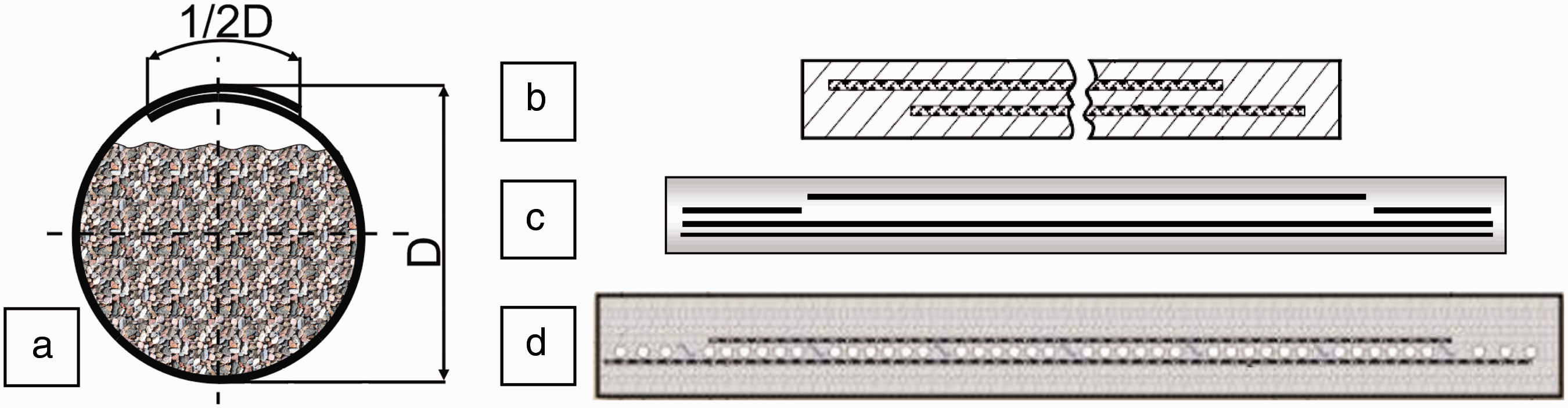
A varied bending rigidity on the width is to facilitate piping of the conveyor belt with an overlap equal to half of the diameter (Figure 1(a)).
The appropriate rigidity of pipe conveyor belts is obtained by a combination of fabric and steel transverse reinforcements. The steel cord belting has a stepped transverse reinforcing cord usually made of nylon fabric. The bending rigidity and the form force of the pipe conveyor have a great influence on its piping, wear and tear, as well as running resistance and stability of pipe conveyor [33,34].
In order to eliminate differences in the forces acting on several layers of the belt carcass, resulting from the position of the fabric in the belt cross-section, on its thickness, one-spacer conveyor belt was modelled.
Weaving process enables modelling the internal structure of the fabric at the very beginning of its formation. Variety of weaves provides possibilities to form the surface of the fabric in order to obtain the best satisfactory properties of the product. This involves both the appearance of the fabric and functional properties of the product. Fabric structure influences a number of qualities such as appearance, smoothness, air permeability, drape, heat insulation, waterproof [35–41].
The main purpose of the performed study was to develop a new woven structure which would restrict the undesirable effect of collapsing the edges of the pipe conveyor belt inward. To achieve the main objective, it was pre-determined, how the weave influences the piping of the belt.
Material
Weaves of particular fabrics and their bending rigidity (G).

The fabrics were made in ‘Metso Fabrics’ company in Lodz on Dornier loom with harness machine. The chosen and produced fabrics have the following weaves: (A) plain weave; (B) twill weave; (C) twill cross weave; (D) satin weave; (E and H) warp rep weave; (F and G) weft rep weave; (K) satin weave with higher density of weft (Table 1). The areal density was about 1530 ± 15 g/m2 except for weft rep weave (F, G) and satin weave with higher density (K), where it was 1650 ± 30 g/m2. These weaves easily enable grouping the warp threads. The measurements of bending rigidity of nine raw fabrics showed that bending rigidity of the fabric along warp and weft depends on the weave (Table 1) and on the length of coverings of the threads set. The number of thread floats also influences bending rigidity. The more the intersections in a set, the higher the bending rigidity in the set. In plain and weft rep weaves of large number of warp intersections (A, F, G), bending rigidity of fabric is the largest. In weaves with long coverings of warp and weft, bending rigidity of fabrics is lower (twill weave B, C, satin weave D) (Table 1).
The fabric after weaving goes to vulcanisation and becomes a conveyor belt [42,43]. The fabrics are positioned in warp direction on the belt.
The analysis of measurements of the transverse flexibility according to EN ISO 703 of the conveyor belts proves that the higher bending rigidity of woven fabric, the lower its transverse flexibility. The minimum value of these parameters for belt F was 0.378 ± 0.002 and maximum value of transverse flexibility for belt D was 0.392 ± 0.003, which corresponds with bending rigidity of woven fabric.
Experiment
A special device was built to measure the pressure of piped belt on six rollers located on its circuit. Depending on the rigidity of the textile and rubber composite, forces may vary from 0 N to 8000 N.
Textile and rubber composites formed in a pipe with a length of approximately 4.5 m, held up with a construction on both sides of the measuring device, were subjected to measurement of pressure forces on six rollers on its circuit. The pipe shape was observed by placing the belt in the additional sets of rollers on both sides of the measurement device (Figure 2). For the conditions used, measurement accuracy of the instruments is in class 1 according to EN 10002-2. Fault in indicating and recording the maximum force at each point of the range does not exceed ± 1%. The accuracy of measurement methods and measurement results is consistent with the standard PN-ISO 5725.
Schema of the device to measure pressure forces of the pipe conveyor belt on the set of rollers (a) entire device, (b) the six movable rollers.
The measuring device consists of two parts: mechanical and electronic. The mechanical part is mainly a frame with six movable rollers (Figure 2(a)). These rollers are made of steel and may rotate around their own axes. The roller diameter is 89 mm and the width is 110 mm. The electronic part is a force sensor in a set of one roller.
This set is removable and enables assembling it in six different positions (Figure 2(b)). The measurement is static and stored in a portable electronic recording unit with the ability to rip the data on the computer.
The relationship between moving the central set about the axis of the measuring device and the curve radius of the belt curvature in the horizontal plane.

After rolling the belt, always the same edge was fitted on the second. The test was repeated three times for each conveyor belt. Except for collecting the measurement data, there were also pictures taken.
Measurement results and discussion
Analysis of results and photos taken during the measurements clearly shows the diversity of piping manners of the belts depending on the weave of fabric carcass. The trend to taking the shape of pipe, which is the actual transverse rigidity of the belt (along weft threads), affects the pressure forces acting on particular rollers. In all conveyor belts tested, collapse of the edges inward was observed (Figure 3), which is the most common problem for users of such belts.
(a) The device to measure pressure forces of the pipe conveyor belt on the set of rollers. (b) The photo of the pipe conveyor belt not touching the top, first roller. (c) The pipe conveyor belt with the edges collapsed inward.
These observations are reflected in the research on the belt pressure on a set of rollers where the top rollers 1 and 2 were not loaded. In this case, total weight of the conveyor belt was arranged on the other four rollers.
Analysis of the results of the forces distribution on the pipe circuit showed, among other things, that high rigidity of fabric A (plain weave) and F, G (weft rep weave) affects low flexibility of the belt, which results in that roller 4 (in the bottom) is less loaded compared to rollers 3 and 5 (Figure 4(a)).
Charts of the distribution of pressure forces on individual rollers for fabrics A and C on the right side showing the influence of the belt rigidity on that distribution.
Belts of high flexibility (C, D, E, H), in which reinforcing fabrics have low rigidity (twill and satin weaves) (Table 1) [44] show the greatest load of roller 4 (bottom) (Figure 4(b)). Depending on the belt, roller 4 was more or less loaded to rollers 3 and 5. For fabrics B and K, force distribution on rollers 3, 4, 5 was almost the same 46 ± 5 N.
Belts arrange asymmetrically in a set of rollers, because there is always an overlap of one end on the other, which causes the asymmetry. On rollers 1 and 2, they were not loaded at all, and on roller 6 (symmetrical to 2) forces were small about 5 N.
Another type of measurement was the analysis of how the belt affects rollers on the arcs. Shifting the middle set of rollers relative to the outside sets allowed conducting measurements of the belt pressure on the rollers at different radii of the arcs.
Reducing the radius of the curvature arc horizontally causes the pressure increase on the rollers on the inside of the arc (Figure 5(a)). Changing the radius results in a significant decrease of the pressure on roller 3 (outside the arc) and an increase on rollers 5 and 6 (inside the arc). The trend is clearly visible in belts H or D (Figure 5). Change of the radius actually does not change the pressure on the bottom roller (4) (Figure 5(c)).
The distribution of forces on a roller when changing the radius of the curvature arc of the belt 400 to 50 m on the example of belt D. (a) roller 3 on the outside of the arc, (b) roller 5 on the inside of the arc and (c) roller 4 in the bottom.
The value of pressure changes when changing the arc is different depending on the weave—for fabric D, the changes are significantly higher than in the case of fabric A which has much larger rigidity [44]. This is due to differences in the bending rigidity of the individual fabrics, and, as a result, conveyor belts. For belts of low transverse flexibility and high bending rigidity of fabrics, the arc change did not significantly affect the change of pressure on rollers 3 and 5. For belts of high transverse flexibility and low bending rigidity of fabrics, changing the radius of the arc, statistically significant, caused differentiation of the pressure on rollers 3 and 5. For elastic belts, the greatest pressure was on roller 4 and the arc change caused that these belts charged more roller 5 and relieved roller 3. For belts of high rigidity, the pressure was statistically higher on rollers 3 and 5 compared to 4, which resulted in statistically insignificant pressure change during the arc change.
What can be clearly stated is that the weave of the belt carcass affects its rigidity, which results in different pressure forces on the rollers. In contrast, the rubber which is the same in each belt does not eliminate the differences of mechanical properties of fabrics [44].
The results of the analysis of the bending rigidity of the fabrics and the pressure forces on the rollers on the pipe circuit allowed to design a new woven structure. Combining the above analysis with the previous analysis presented in the article [44] enabled the development of a new woven structure.
Formation of the new woven structure of variable bending rigidity on its width symmetrically to the longitudinal axis of the belt
The idea that guided this research was to develop such a woven structure to vary the bending rigidity of the belt on its width. Using the information about the existing pipe conveyor belts, it was decided to shape differences in belt rigidity symmetrically to its longitudinal axis.
Analysis of the mechanical properties of fabrics and conveyor belts with reinforcement based on these fabrics [44] and analysis of belts pressure on the rollers on the pipe circuit both allowed to optimize individual sections of the belt on its width to retain the belt in a predefined manner.
A fabric and a belt were produced of the same width of 100 cm, as nine fabrics described earlier. Taking into account the overlap of the radius length, the pipe circuit is 86.4 cm of radius 13.7 cm.
The belt was divided into three different sections symmetrically to its longitudinal axis to vary its bending rigidity on the circuit (on the belt width). Individual fragments of the belt were made in a single weaving process of one fabric but different weaves.
Half of the circle circuit was divided into three arcs: (A) 45°, (B) 90° and (C) 45°. This division is symmetrical to the longitudinal axis of the belt. The last arc was extended by half the circle radius because of the belt overlap, i.e. C′ 28.66° (Figure 6).
Division of half of the piped belt into elements (a) 45°, (b) 90°, (c) 45°, (c′) 28.66°.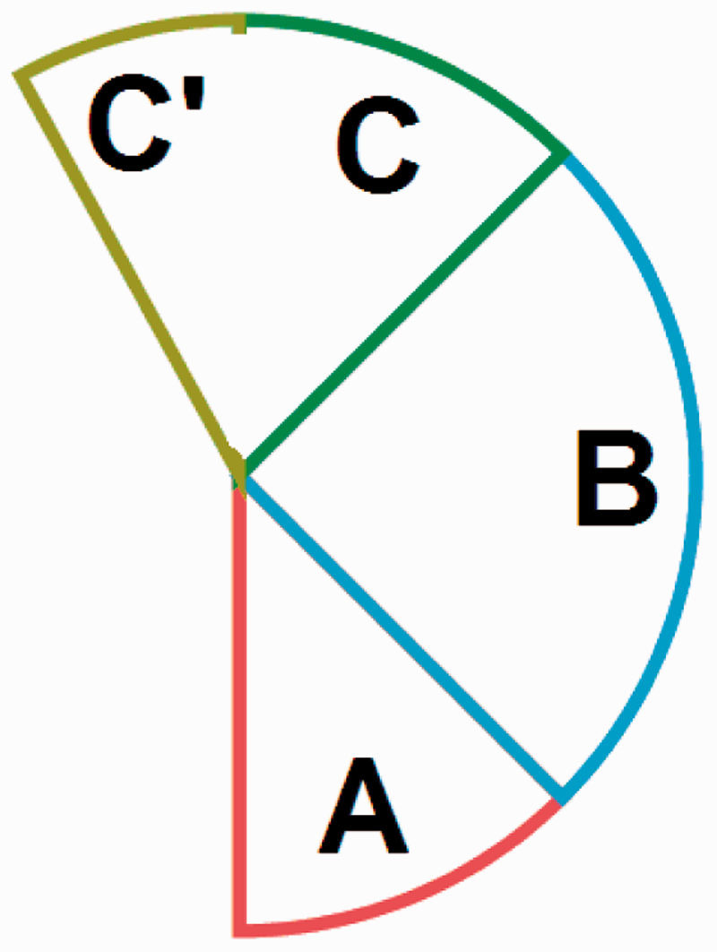
It is provided to divide half of the circle in three parts, because the arc length of variable rigidity must be sufficient for weaves used in particular fragments to have an actual and effective impact on the belt rigidity.
Such division of the circuit, the width of the belt due to the rigidity of the individual elements preferably affects the belt drape, i.e. the edges do not collapse inward of a closed pipe, while an easy formation of the trough.
Careful analysis of the effect of weaves on fabrics rigidity as well as on transverse flexibility of the belts and belts pressure on a set of rollers allowed to assign the following weaves to the arcs.
Weaves applied in a new woven structure.

Arc B has weave of the fabric reinforced with back weft. The main objective of this section is to strengthen the belt structure on this arc of the circle. Back weft weave has a compact structure of high rigidity, which results in spontaneous unfolding of the belt. The forces acting on that rigid element, located at this point of the circle act centrifugally on the belt, which contributes to a better belt adhesion to the rollers.
The last fragment consisting of arcs C and C′ is woven with a rep weave 1/1 pitch 0001000. This weave does not prevent building up of threads in part B of the belt. It is rigid enough so that the edges of the belt do not collapse inward while facilitating smooth closing it. The warp in this weave has long interlaces, which is advantageous for the belt strength. The measurements of the belt made for this weave show that its transverse flexibility is similar to the belt of plain weave (low), however, considerably exceeding strength along the warp and weft [44].
A new woven structure was designed with standard Dornier loom with electronic dobby able to control 20 harnesses. The individual pieces of fabric have weaves: satin, back weft and warp-rep (Table 3). Weaving of this fabric did not require any investment costs. The most complicated thing was a method of drawing-in harnesses because they were not typical, in sequence, but modified, dependent on weaves.
While various weaves were decided to be implemented on the fabric width, unconventional way of threading the harnesses should be applied. Satin weave is designed for eight harnesses, back weft weave for four harnesses and warp-rep weave for the next four. The remaining four harnesses are designed for selvage.
The weaving parameters were the same as during the previously made nine tests, i.e. fabric with warp PES 2200 × 4/60 (four threads of 2200 Tex twisted together with 60 twist/m) and sett 120 threads/dm and weft PA6.6 1400 × 5/90 (five threads of 1400 Tex twisted together with 90 twist/m) and sett 43 threads/dm and weaving width 118 cm with reed 30 blades/dm, four threads between the blades.
After making, the newly designed woven structure was impregnated with latex in order to improve the rubber adhesion and vulcanized in the same way and with the same parameters as the previous belts. Finally, the belt was made of the width of 100 cm with protectors 2 + 2 and thickness of 7.3 mm (Figure 7).
New woven structure covered with latex (upper part) with the vulcanized element.
Experimental verification of the new belt
Results of measurements of different parts of the new woven structure and transverse flexibility of the belt.

Warp sett was different within one fabric. In satin weave, where there are long interlaces, warp could build up increasing its sett. Weft sett was the same for all parts of the fabric.
Maximum thickness was observed for the part woven with back weft weave. This is due to the construction of the weave. Satin weave, where weft threads do not build up, had lower thickness. Warp tends to group and lay on the surface of the fabric. The smallest thickness was in the case of rep weave.
The value of transverse flexibility of the new belt is in upper limits compared to the results of the previous nine belts [44]. This may mean that this belt will tend to take the trough shape spontaneously.
Since the strength along warp exceeds 550 N/mm, the new belt can be classified with full responsibility as a minimum belt EP550, which was a benchmark and reference point while designing the fabric.
Measurements of the pressure of piped, newly designed belt on a set of rollers located on its circuit were made. Analysis of the measurement results and photos taken during the experiment indicates that the new piped belt tends to maintain its shape and the edges do not collapse inward (Figure 8). The belt puts pressure on all the rollers on the circuit (Figure 9), which will certainly contribute to its longer durability. More even distribution of pressure forces on the belt circuit is beneficial for reducing the destructive forces acting when the belt charges only the bottom rollers, as it was in the case of nine belts tested previously (Figure 4).
Piping of the new belt (a) View on the rollers, (b) View on the cross section of the pipe conveyor belt. Distribution of pressure forces of the new belt on the rollers on its circuit.

Analysis of the changes in the belt pressure on the rollers while reducing the radius of the arc curvature in the horizontal plane shows that for roller 3 (on the outside) pressure changes are within statistical error. The increase in pressure of the belt is more visible for rollers 4 (bottom), and 5 (on the inside of the arc) (Figure 10). These results show that new conveyor belt combines higher transverse flexibility and lower rigidity of the nine previous fabrics. For roller 3 (on the outside), the changes of pressure forces are not statistically important as for belts of low transverse flexibility (A, F) but the pressure increases on roller 5 (inside the arc), as it was for belts of high transverse flexibility (D) (Figure 5(b)).
Distribution of forces on roller 3 (a) (on the outside of the arc), roller 4 (c) (bottom) and roller 5 (b) (on the inside of the arc) while changing the radius of the arc curvature of the new belt from 400 to 50 m.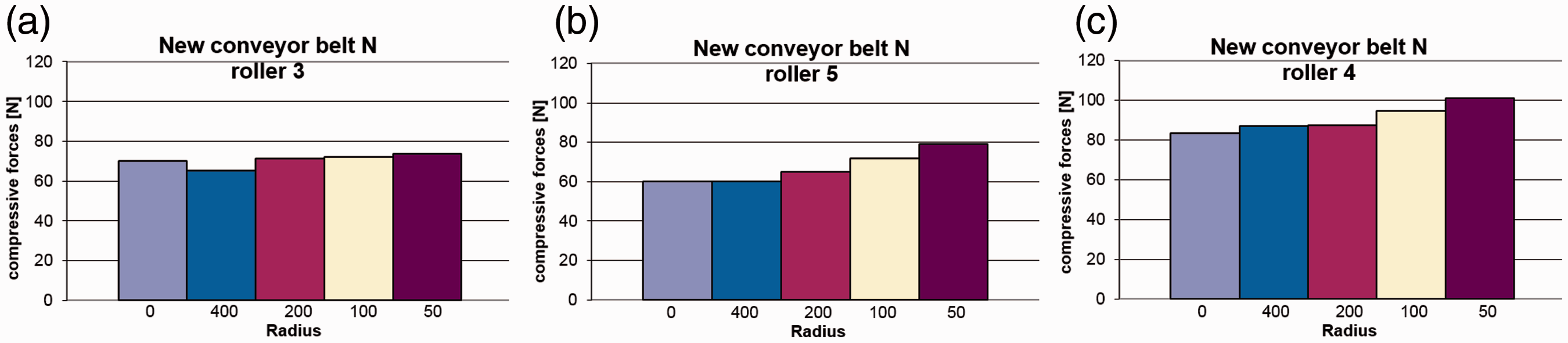
In summary, it can be assumed that the objective of the work was achieved by changing weaves of the fabric on its width in 1-spacer belt, which results in that the belt edges do not collapse inward while maintaining high transverse flexibility and better closing properties.
The structure of the fabric along the belt axis is formed so as to achieve a high degree of flexibility, thereby minimizing the internal stresses while returning of the belt on the end rollers of the conveyor. Such structure of the belts paves the way for new possibilities of their design.
Conclusions
The problem of conveyor belts has been studied and developed for many years; however, manufacturers are still working on new structure possibilities of pipe conveyor belts. One of the problems with the existing solutions is collapsing the edges of the belt inward.
There were made fabrics being reinforcement for 1-spacer conveyor belts. A study of mechanical and structural properties of these belts was conducted [44]. This paper presents the results of measurements of pressure that the piped belts exert on a set of rollers located on their circuit and their transverse flexibility. The following conclusions were drawn on the basis of the first part of the study:
High rigidity of the fabric affects low flexibility of the belt, resulting in that the bottom roller is less loaded compared to the side rollers. Belts of high flexibility, in which reinforcing fabrics have low rigidity, are characterized by the highest load of the bottom roller. Reducing the radius of the belt arc increases pressure on the rollers on the inside of the arc and decreases it on the outside.
Careful analysis of the obtained results allowed modelling a new woven structure of variable bending rigidity symmetrically to its longitudinal axis by selection of appropriate weaves. Production of the fabric, its vulcanization and making the belt of innovative construction allowed a positive verification of the assumptions.
The conveyor belt was made with a possibility to take a pipe shape and close whose edges do not tend to collapse inward. Its construction allows to minimise the stresses generated in the structure at the moment of return of the conveyor belt by eliminating multiple spacers and gaining high transverse flexibility. One-spacer belt has minimal thickness, which reduces its weight, thus reducing the resistance movement while scrolling the belt through the drums. What is also very important is that during production of this new type of woven fabric any investment costs were not necessary.
This solution is an important step in improving the belts in the industry, which will help to better protect the material carried by the belt from weather conditions such as rain and wind, thus taking care of the environment.
In addition, the idea of forming different mechanical properties within one fabric through the implementation of different weaves on its width could spread to other areas of industry in which there is such demand.
Footnotes
Acknowledgements
Conveyor Belts Factory Wolbrom S.A. is kindly acknowledged for delivering the materials and producing new belt. Special thanks to Marek Gardela for useful cooperation. Metso Fabrics Lodz is acknowledged for help in production of woven fabrics.
Declaration of Conflicting Interests
The author(s) declared no potential conflicts of interest with respect to the research, authorship, and/or publication of this article.
Funding
The author(s) disclosed receipt of the following financial support for the research, authorship, and/or publication of this article: The work was funded by National Science Centre (Poland), Project 3215/B/T02/2011/40.