
Abstract
The demand for woven spherical shapes, particularly in applications such as fiber-reinforced plastic (FRP), is increasing. However, the production of woven two-dimensional fabrics in three-dimensional (3D) shapes using conventional weaving machines faces technical limitations. As a result, draping and cutting processes are commonly employed to transform flat woven fabrics into 3D shapes, leading to challenges such as structural distortions, thread interruptions, layer overlaps, and high cutting losses. To address these issues, this research introduces a novel weaving technology that enables the creation of spherically curved woven fabrics utilizing conventional weaving machines. Using the developed technology it is possible to fabricate double curved fabrics without the cutting and usual draping processes that can be implemented to reinforce FRP components. The study presents mathematical models capable of calculating the required 3D surfaces for such fabrics. By adopting this technology, the need for draping and cutting processes can be eliminated, leading to improved quality and structural integrity of the final product.
The production of three-dimensionally shaped fiber-reinforced plastic (FRP) has traditionally relied on the cutting and layering of flat woven or stitch-bonded fabrics. However, this approach often results in thick spots in the final product due to overlaps at the joints of individual cut parts. Alternatively, draping flat fabrics into the desired three-dimensional (3D) shape can lead to a wrinkled final product, especially when using stiff high-performance fibers such as carbon fiber or glass fiber.
To overcome these limitations, extensive efforts have been made to develop technologies for the direct production of 3D textile shapes. Research activities have primarily focused on reducing process costs by creating near-net-shape semi-finished products, eliminating the need for cutting and layering, and enhancing the draping capabilities of textiles using advanced weaving technologies. These advancements enable the creation of 3D shapes structures that are free from wrinkles and exhibit superior structural integrity, even when utilizing high-performance fibers.1 –3
Significant progress has been achieved in textile fabrication technology, particularly in the areas of knitting and weaving. Knitting technology has seen developments in both flat knitting machines and multiaxial knitting machines.4 –7 Furthermore, there is the possibility of producing 3D textiles by means of braiding and winding processes.8 –10 However, these are usually limited to rotationally symmetrical geometries and often require a core. Similarly, advancements have been made in weaving technology for different types of 3D structures such as multilayer, spacer, or tubular fabrics.11 –20 In most developments, the fabrics are produced flat and then draped into the desired 3D surface 21 or created by selectively joining individual layers and then shaping them. 22
For instance, variable take-off mechanisms have been designed for weaving machines, allowing for the extraction of varying warp thread lengths for the production of three-dimensionally shaped fabrics. However, the adaptability of the variable take-off system for producing different shapes is limited, reducing flexibility. Consequently, the need remains for a weaving process that combines high productivity with the ability to introduce variability. In this regard, the authors have developed a new weaving process for the production of 3D shapes. 23 The desired spherical curvature of the fabric is achieved by incorporating different lengths of warp yarns. This incorporation is made possible by substituting the conventional take-up mechanism of the weaving machine with a fabric retainer system, resulting in extraction of different lengths of warp yarns. To establish the relationship between the interlacing pattern of warp and weft yarns and the resulting incorporation, mathematical models describing the weaving process must be developed. These models aim to capture the correlation between the desired geometry and technological constraints. In this study, the developed model is presented, applied, and evaluated.
Overall, the research described in this paper addresses the challenges associated with the production of woven 3D shapes by the conventional weaving process, providing insights into novel weaving technologies and mathematical models that enable the direct creation of complex textile shapes.
Definition of the volume-enclosing surface of the considered fabrics
In the literature, 3D textile shapes are often defined as voluminous shapes that consist of multiple thread systems arranged in a layered manner. These shapes possess thread systems in all three spatial directions, making them unsuitable for description using a two-dimensional (2D) coordinate system. In addition, textile shapes that exhibit one- or two-axis curved surfaces without any prior mechanical manipulation, thereby enclosing or surrounding a volume, are also considered 3D textile shapes. The specific type of textile and the number of thread sets used are irrelevant in this classification. However, it is necessary to further classify these shapes based on their enclosing or surrounding surfaces in the present context.
Closed shapes refer to 3D textile shapes that completely enclose a volume, such as tubular or spherical shapes. Furthermore, a subdivision can be made based on profile shapes. These shapes feature profiles with defined cross-sectional geometries, such as L, T, or I shapes, running along a straight or curved profile axis. It is important to note that textile shapes transformed into 3D forms through subsequent processing steps, such as deep-drawing, draping, or assembling cut parts, are not considered as 3D textile shapes in this context.
A spherically curved fabric is a specific type of 3D shape where the surface encloses a volume and exhibits regular characteristics. This can be further divided into a hemisphere as soon as the surface encloses half of a spherical volume. In this context, “regular” refers to the property of the surface mapping being homeomorphic, continuously differentiable, and injective for each point on the surface. For the surfaces discussed in this paper, we impose additional restrictions to further define their properties.
the points of the surface are always positive; the project of the surface from ℝ3 → ℝ2 is bijective, and thus the surface has no points with equivalent coordinates with respect to (x, y, z).
Furthermore, the type of curvature is defined. Only biaxial shapes whose curvature axes are not parallel are considered, such as shell parts or hemispheres (Figure 1(b)). These objects are defined as double-curvature structures. Distortion-free unwinding is only possible with uniaxial curved structures whose curvature axes run parallel (Figure 1(a)). These types of curvature are not determined as spherically woven structures. In the following, the surface of double-curvature fabrics are considered.
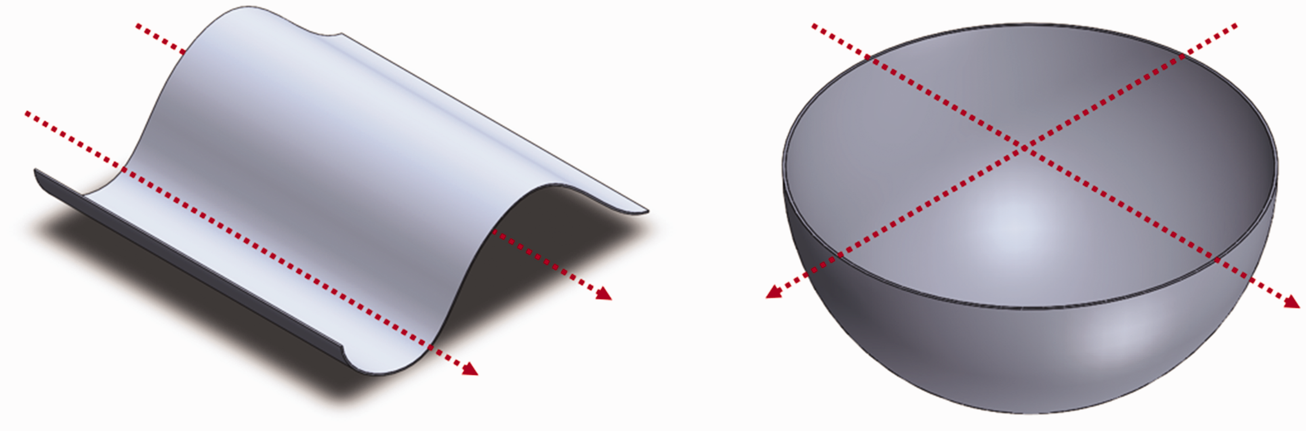
(a) Shape with a single curvature. (b) Shape with a double curvature.
Description of the developed method
The production of conventional fabrics involves the orthogonal interlacement of longitudinal warp yarns and transverse weft yarns. 24 The spacing between the longitudinal warp yarns is determined by the inserted weaving reed and subsequent feeding of the warp yarns. The distance between the transverse weft yarns is influenced by the chosen weft density, which is adjusted based on the speed at which take-up of the weaving machine operates. Higher take-up speeds result in lower weft densities, while lower take-up speeds yield higher weft densities. The weft insertion speed remains constant during the weaving process. The weft density stays constant across the fabric width, resulting in a consistent length for the warp yarns within the fabric structure.
To transform fabrics into spherically curved shapes without introducing negative structural distortions, varying thread lengths must be incorporated. These varying thread lengths along the fabric width through crimping warp yarns differently by introducing different weave structures (plain, twill, etc.) in predetermined regions cause the fabric to naturally curve into a 3D spherical shape. For instance, an increase and decrease in warp thread lengths across the fabric width creates a curved shape (refer to Figure 2).
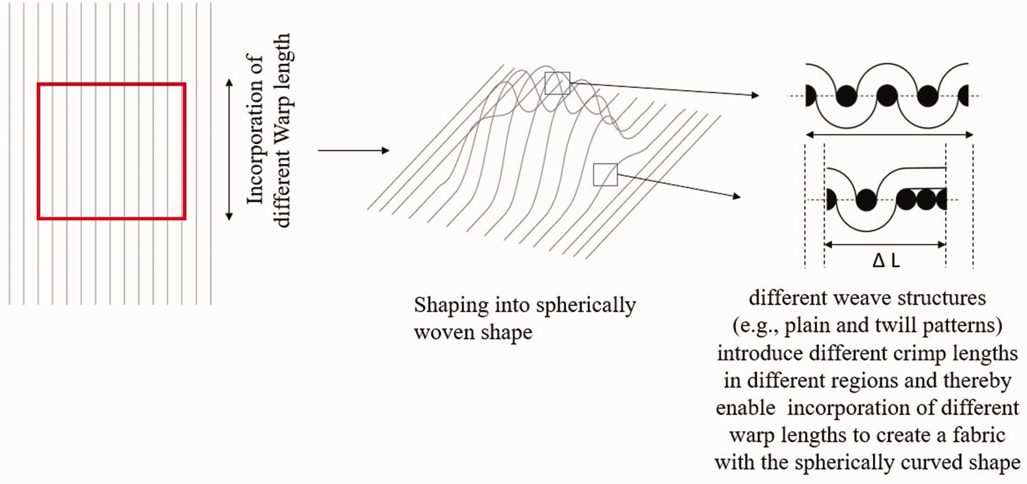
Creation of a spherically curved structure via different warp lengths.
Conventional weaving machines typically take up warp yarns uniformly, which poses a limitation for generating a fabric curvature. To address this limitation, a take-up-free weaving technique has been developed. 23 This new technique retains different warp lengths across the fabric width by utilizing various weave patterns in different predetermined regions for the interlacing of weft and warp yarns. The jacquard technique is employed for shedding, allowing control over each individual warp thread. Specifically, shorter warp yarns can be incorporated when the number of crossing points with weft yarns is reduced (see Figure 2). Due to the different incorporation of the warp yarns, caused by the locally different interlacing of the fabric, the warp yarns are incorporated into the fabric with different lengths. These differences in length cause the fabric to acquire the double-curvature shape. The curvature of the textile structure is created by changing the warp thread lengths. The weft yarns are inserted with an excess length so that they run over the curving. After the fabric has been produced, it is removed from the weaving plane and manually molded to shape.
Referring to the introduced definition of the characteristic of the 3D shape of the fabrics, in this work a 2D fabric is produced, the shape of which has a double-axis curved surface. We do not produce multilayer fabrics, which are often referred to as 3D fabrics, due to the additional thread course in the fabric thickness direction.
By eliminating the conventional take-up mechanism of the weaving machine, the weft yarns are pushed by the reed along the fabric width, leading them to be close to each other. As a result, different intersections of the warp and weft yarns lead to different incorporation of the warp thread lengths in specific fabric areas. Consequently, different weft thread densities are observed across the fabric width, resulting in varying warp thread lengths. As previously described, a conventional take-off is not used. To retain the fabric at the fabric-fell position, the authors have developed a completely new solution. Here, the movement of the fabric away from the fabric-fell is carried out by the movement of the weaving reed. The fabric is pushed away from the fabric-fell, so to speak. To prevent the fabric from slipping back into the fabric-forming zone, a retaining hook system was developed.
In this innovative fabric retaining method for weaving machines, the authors have devised a unique approach to address the limitations of traditional variable take-off techniques. Here, the movement of the weaving reed is harnessed to efficiently push away the fabric from the fabric-fell position. By coordinating the motion of the weaving reed, the fabric is effectively pushed away from the fabric-fell into the retainer hook system, facilitating a smooth extraction process.
To ensure that the fabric remains securely outside the fabric-forming zone, a retaining hook system has been designed and implemented. This system comprises hooks strategically positioned to prevent any slippage or re-entry of the fabric into the fabric-forming zone. The retaining hooks effectively hold the fabric in place as it is pushed out of the fabric-forming zone by the weaving reed, ensuring a reliable and efficient fabric advancing process. In detail, a double hook system was developed that is installed on a platform of the weaving machine. As shown in Figure 3, the weft thread inserted last is moved along the lower hook system into the noses of the upper hook system and fixed there. This secures the entire fabric-fell and prevents it from slipping back. The installation of the implemented arrangement in a rapier weaving machine is shown in Figure 4.
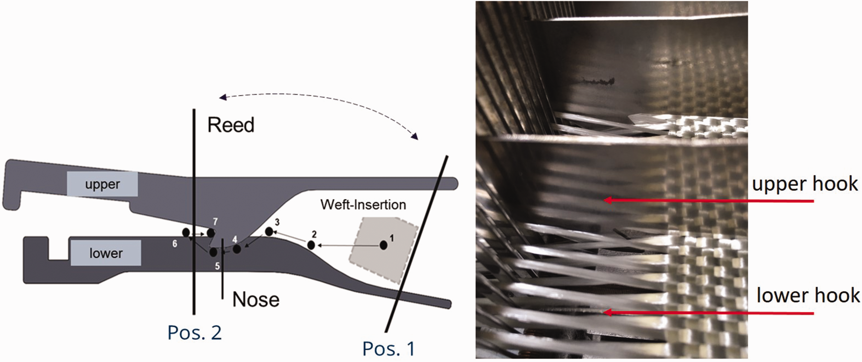
(a) Hook system for retaining the fabric at the fabric-fell position. Numbers 1–7 indicate the path of the inserted weft pushed by the reed and (b) Installation of the hook system.
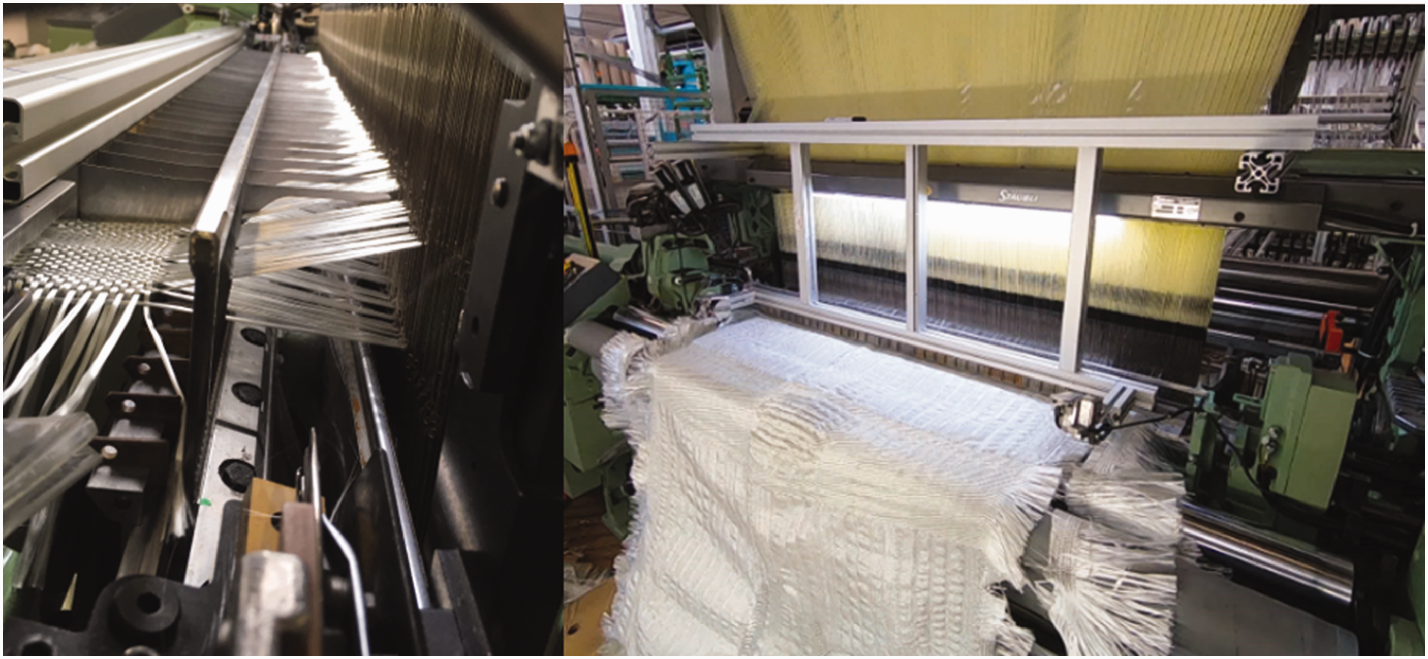
Installation of the retainer hook system for retaining the fabric at the fabric-fell and the emergence of the double-curvature fabric from the weaving machine.
To achieve the desired 3D shape, a mathematical process-describing method needs to be developed to determine the required warp thread lengths and arrange the corresponding weave areas in the overall weave pattern. This method ensures the accurate incorporation of the necessary weave pattern variations throughout the fabric manufacturing process.
Mathematical modeling approach for take-up-free woven structures
The primary challenge in take-up-free weaving is to accurately calculate the required interlacement between the warp and weft yarns to achieve the desired curvature. This process can be divided into the following distinct steps:
detection and description of the curved surface; covering the surface with virtual warp and weft yarns; traceability to interlacing of the weft and warp yarns.
Detection and description of the curved surface: the surfaces of simple double-axis curved geometries can be described very well with second-degree surfaces.25,26 These surfaces are called implicit surfaces and can be described by the equation of form, where the general second-degree equation within the Cartesian coordinate system can be represented as follows:

This representation represents a mixed term due to the xy, xz, zy components, whereby the principal axes are not parallel to the coordinate axes. By means of the principal axis transformation, these mixed terms can be eliminated, resulting in the following equation:

From this equation, general second-degree surfaces such as ellipsoids can be described as follows:
where a,b,c are the coefficients and x,y,z are the non-homogeneous variables.
Describing surfaces through second-degree equations becomes exceedingly complex as surface complexity increases. Moreover, a corresponding equation must be developed for each geometry, making this method inefficient. For this reason, surface capture through interpolating methods is more practical, allowing any surface to be derived from a computer-aided design (CAD) model and calculated. Common software tools can import the CAD file and interpolate surface points, which can be used for further calculation and allocation of the geometry using virtual warp and weft yarns. In this study, the geometry was captured using MATLAB software. The CAD surface of the target geometry generated by any CAD software is imported as an STL file into MATLAB, which returns a vector containing the x,y,z-coordinates of the surface points. These points can be used to reproduce virtual thread courses on the geometry and to determine their lengths.
Covering the surface with virtual warp and weft yarns: in order to infer the warp thread lengths to be inserted, the geometry must be occupied with virtual warp and weft yarns in advance. For this purpose a calculation method for rotationally symmetric spherically curved surfaces was developed.
Method via smoothing splines
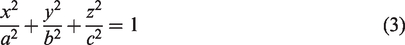
The proposed methodology involves the implementation of virtual yarns to cover the geometric structure, with the warp and weft yarns aligned horizontally and vertically across the surface. To define these yarns, initial start points are generated along the x- and y-axes. The intersection points between these directions are then identified, providing x-, y-, and z-coordinates for each crosspoint. Utilizing these coordinates, the paths of both the weft and warp yarns are determined by employing a smoothing spline algorithm implemented in MATLAB, as described in Equation (4). The smoothing spline function is determined by specifying the smoothing parameter u and the corresponding weights wi. A value of u in the range of 0–1 is chosen, where 0 generates a least-squares linear fit to the data, while 1 produces a cubic spline interpolant. The resulting output is depicted in Figure 5, illustrating the plotted outlines of the weft and warp thread paths:

Covering the surface with virtual warp and weft yarns via the smoothing spline.
Adjustment of the crossing points
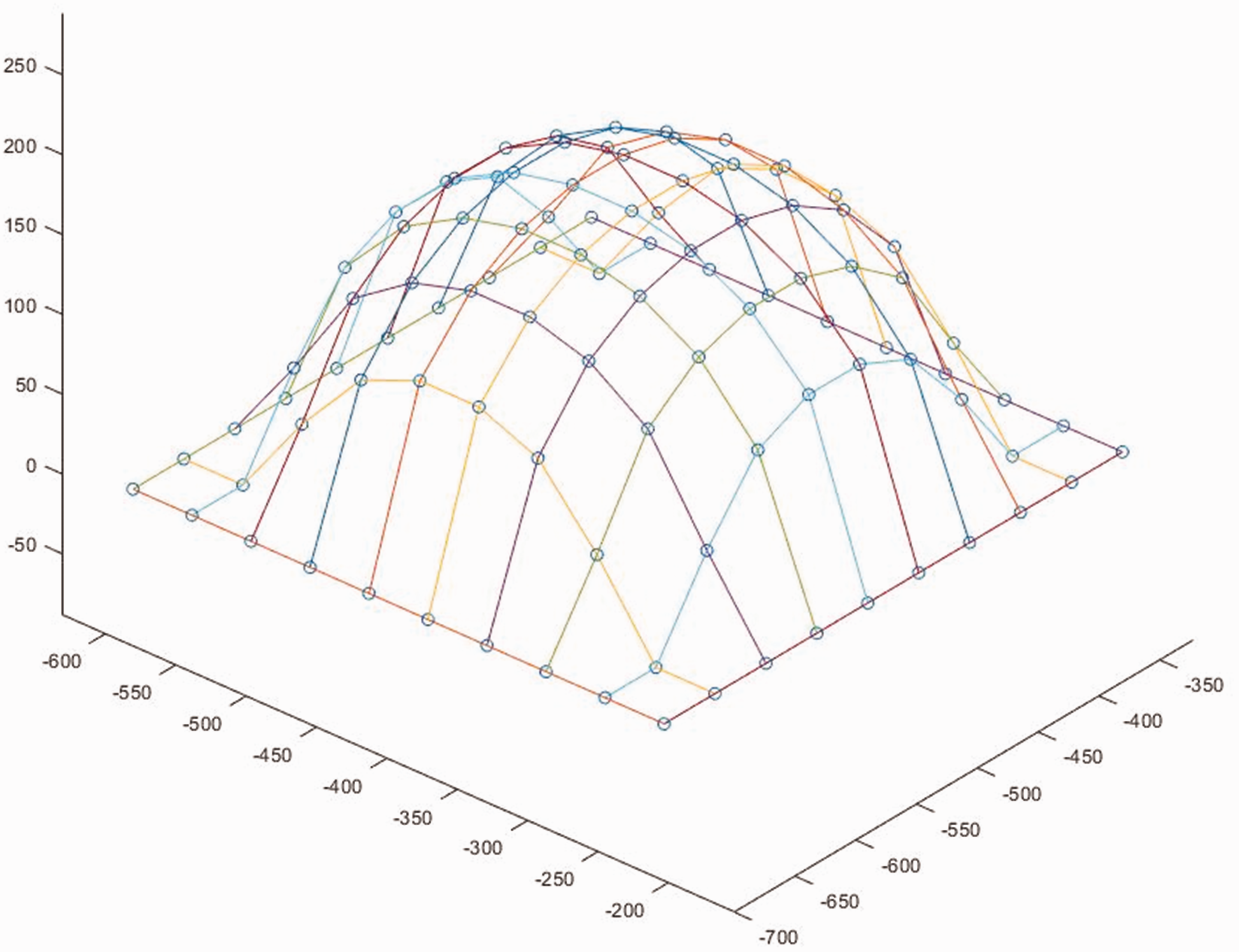
In utilizing the developed method, it was observed that the alignment of yarns across the surface at right angles does not accurately represent their actual course. This discrepancy is particularly evident in the edge areas and poles. To address this issue, an iterative adjustment process was implemented, employing a numeric optimization algorithm.
The algorithm is designed to achieve a uniform distribution of 3D distances between each point and its neighboring points. During each iteration, the distances to the connected points in both the weft and warp directions are calculated for each crossing point. The ratio between the distances in the warp and weft directions determines the direction and magnitude of the shift applied to the current crossing point. Specifically, if the current crossing point is closer to the center of its neighboring points, a smaller step size is used. By moving one point at a time and reducing the step size by a constant factor β, the solution is allowed to converge. The procedure is illustrated in Figure 6, where the green boundary points remain fixed while the current point is shifted in relation to its neighboring points (represented by black dotted lines). Subsequently, the next point (blue) is moved following the same pattern. The distances dx are computed as the length of the curve between two points on the surface. The calculation process is repeated until the current distance in the x- and y-directions is below a fixed value compared to the previously calculated distances. The result of adjusting the cross points to calculate the hemisphere is shown in Figure 7.
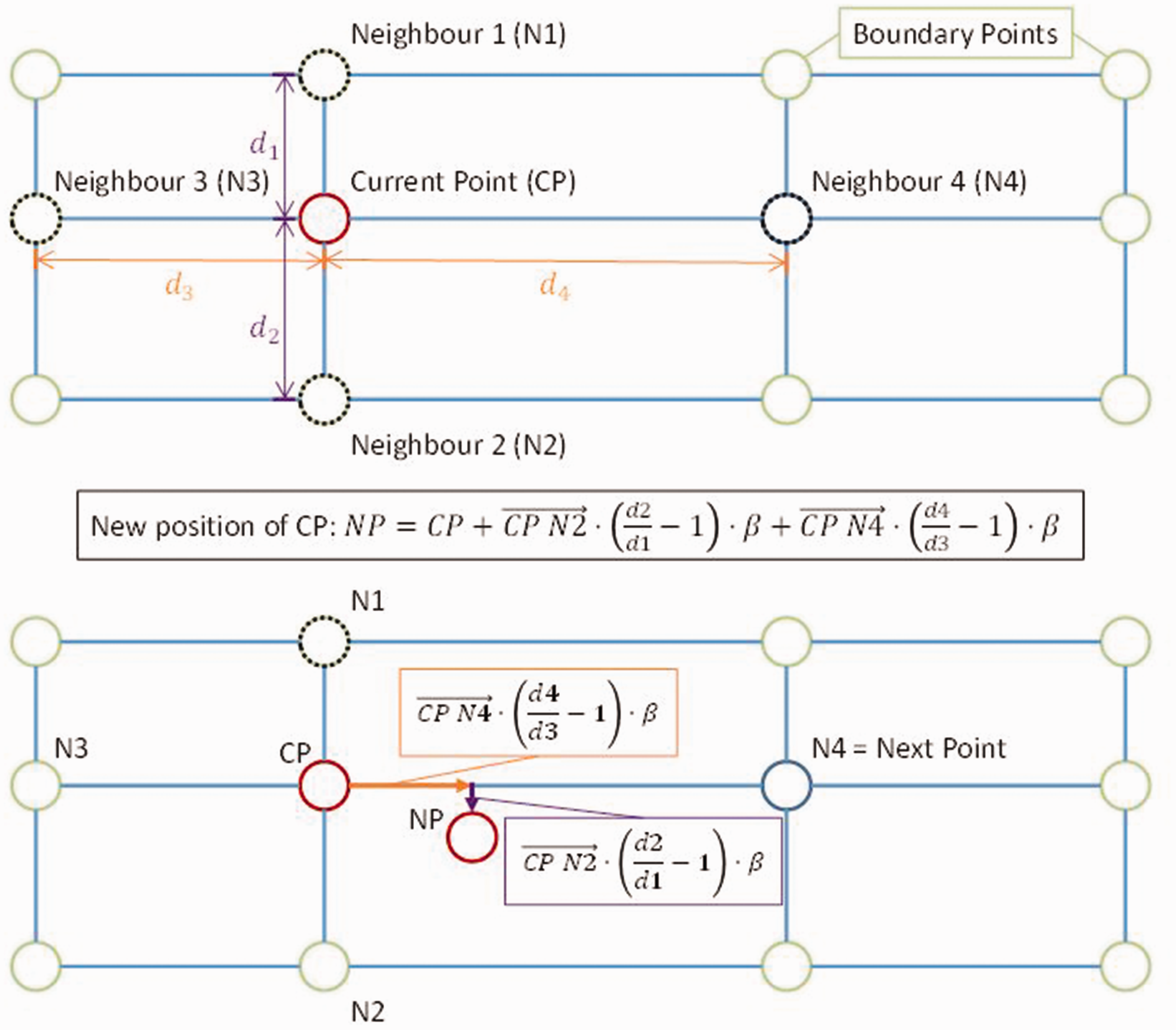
Illustration of the crosspoint adjusting algorithm for one iteration (color online only).
Adjustment of crosspoints to optimize the course of the yarns.
Traceability to interlacing of the weft and warp yarns: in the absence of conventional take-up mechanisms, the warp yarns are incorporated with varying lengths based on the selected weave pattern. The incorporation of warp lengths must accurately replicate the calculated lengths. This entails locally extending or reducing the thread distances in accordance with the existing curvature. Leveraging the Jacquard technique, individual control of each warp thread allows for shedding changes or maintaining the previous position. Consequently, different warp thread lengths can be incorporated into the structure based on the number of intersections between weft and warp yarns. The weft yarn length is determined by the pattern width. As the developed technology only allows a change of the warp yarn lengths, the remaining draping of the structure takes place in order to achieve the curvature in the weft direction.
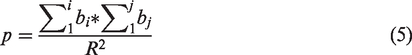
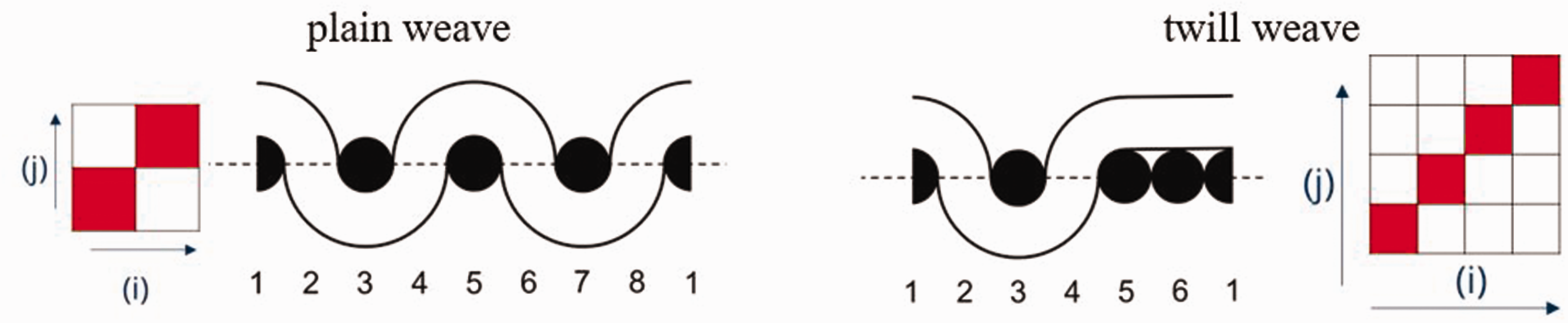
To determine the diverse incorporation of warp lengths using different weaves, a density factor for the weave pattern can be computed. The factor is applied for 2D tissues and is part of the calculation of tissue density according to Walz and Luibrand.
27
The factor is derived from the number of thread intersections within a weave unit, calculated by summing up the cross-sections for each column and row, and then dividing it by the maximum possible intersection (plain weave) (refer to Equation (5)). For instance, the density factor for the twill weave illustrated in Figure 8 is 0.563:
Calculation of theoretical density factor of twill weave.
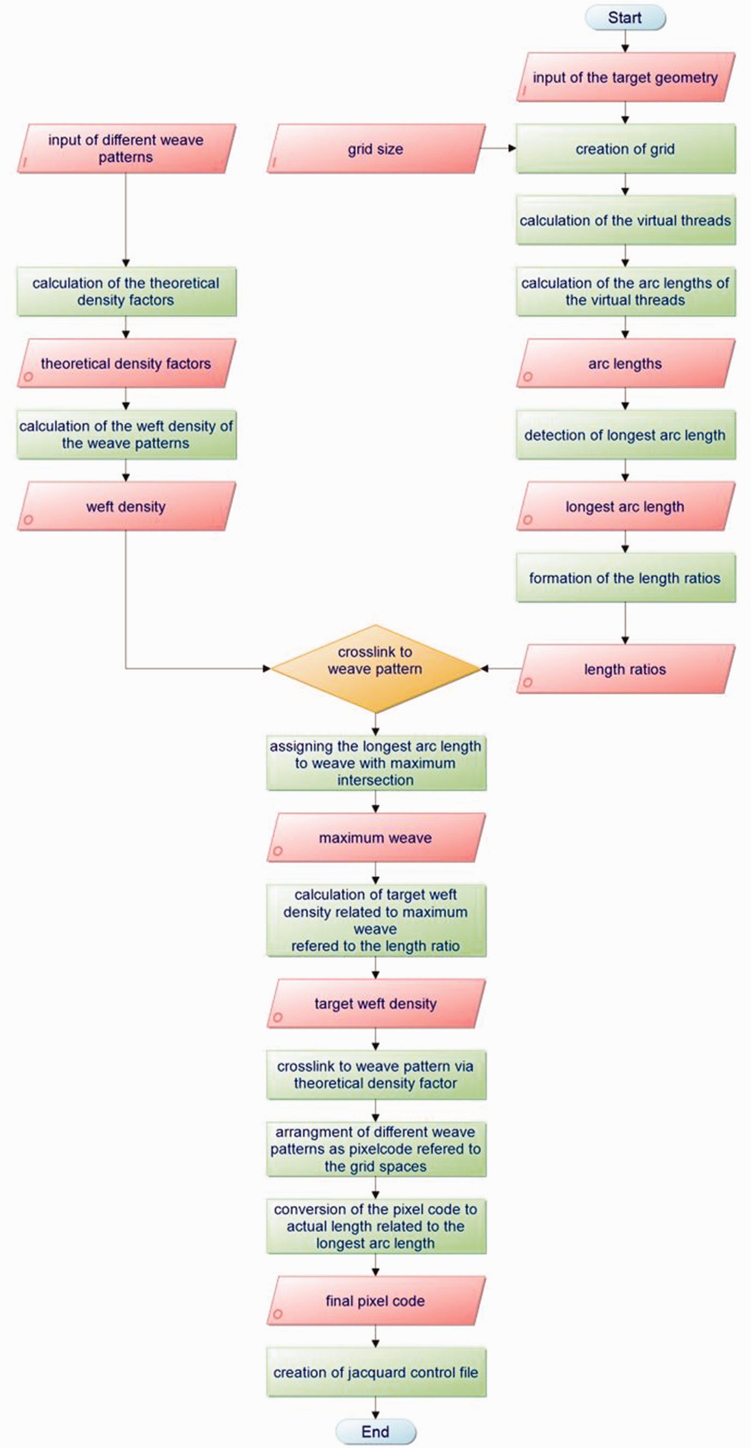
Developed program routine: a program routine was developed to assign the necessary weave patterns for generating the desired arc lengths and overall spherical curvature of the structure (refer to Figure 9). The process begins by inputting the target geometry and selecting different weave patterns. The grid size for covering the surface is chosen to calculate the virtual thread lengths. Utilizing an adjustment algorithm developed for optimizing the course of the yarns, the arc lengths of individual virtual warp yarns are calculated. Subsequently, a length ratio is determined for each virtual warp thread in relation to the longest warp thread. The ratio of the theoretical density factor associated with each weave pattern can be assigned to these length ratios. However, it is important to note that this ratio does not correspond to the actual length ratio of the warp yarns. To establish this relationship, the weft density of the respective weave areas is considered. By creating a ratio of different arc lengths using Equation (6), the weft density can be directly associated with the warp length required to achieve the desired weave pattern. This enables the assignment of the ratio of bow lengths to the ratio of weft densities, defining a selection of potential weave patterns in advance.
Roadmap of the developed program routine.
To determine the weft densities of individual weave patterns, experimental evaluation is necessary. Accordingly, selected weaves were produced using the developed take-up-free weaving technology. A rapier weaving machine with a nominal width of 1400 mm was utilized, and the shedding was performed using a Jacquard shedding device with single thread control. Glass fiber rovings with a titer of 1200 tex were employed for the warp and weft thread material. The warp thread density was set at 5 yarns per cm, drawn tangentially from a creel equipped with disc bobbins. The creel was fitted with a passive compensation system to maintain consistent warp thread tension forces throughout the weaving process:

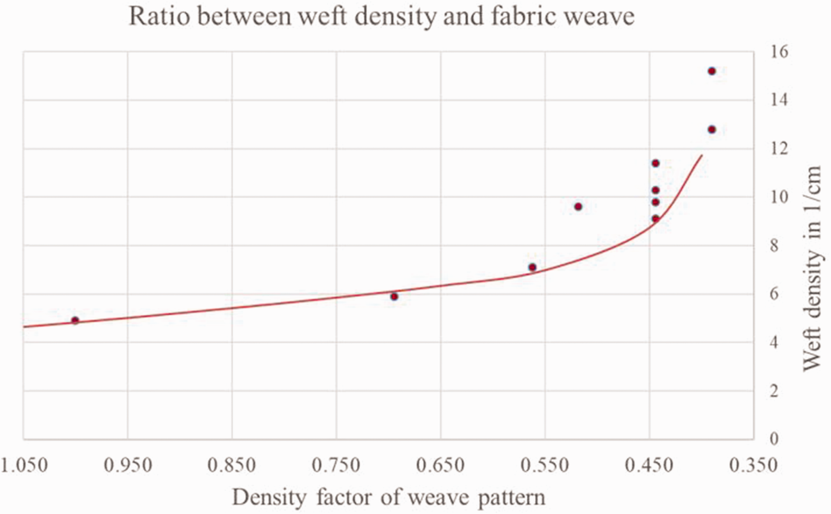
The relationship between the weft density and density factor for the current weave type is depicted in Figure 10. It can be observed that the weft density decreases as the density factor increases. By employing numerical methods, a function based on Equation (7) was developed using the measured data points. This function allows for the determination of the weft density for any given weave pattern, considering the fiber material retention and machine settings. Consequently, the weft density for a specific density factor in the target area can be predetermined, leading to an optimized allocation of the weave pattern for inserting the defined warp thread length. The developed program routine utilizes Equation (7) to assign the previously selected weave patterns to their respective arc length ratios.
Ratio between weft density and the density factor of the weave pattern.
To ensure the accurate alignment of the woven length with the overall size of the weave pattern, the arc length of the longest warp thread is calculated based on the attainable size of the corresponding weave pattern. This calculation is utilized to adjust the pixel size of the resulting image file, while also considering the specific rapport size of each chosen weave pattern. The areas are visually represented in the image file, with distinct colors indicating the required weave pattern for each specific arc length. Subsequently, the image file is employed to generate the control file for the Jacquard machine using EAT Design Scope software.
In summary, the developed methodology facilitates the application of take-up-free weaving technology to create weave patterns that correspond to the required lengths of the warp yarns. Through experimental evaluation of selected weaves, the methodology accurately determines the weft densities necessary to achieve the desired weave pattern:

where p is the theoretical density factor (with Equation (5)) and the equation constants are a = 2.458e + 04, b = –21.77, c = 10.46, and d = –0.7742.
Experimental investigations
The manufacturing process of a hemisphere was achieved using the developed take-up-free weaving technology and advanced calculation models. The dimensions of the selected geometry are shown in Figure 11.
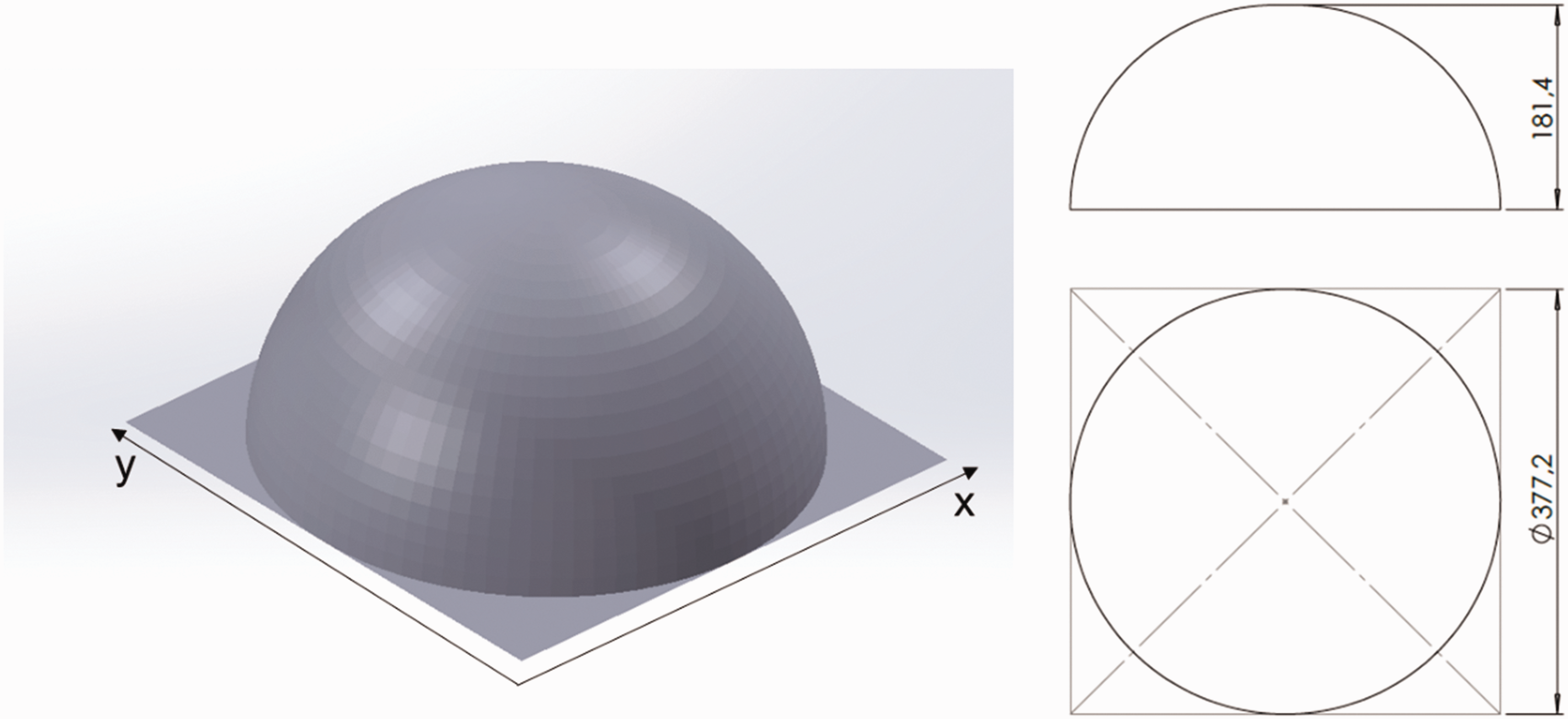
Computer-aided design illustration of the hemisphere (dimensions in mm).
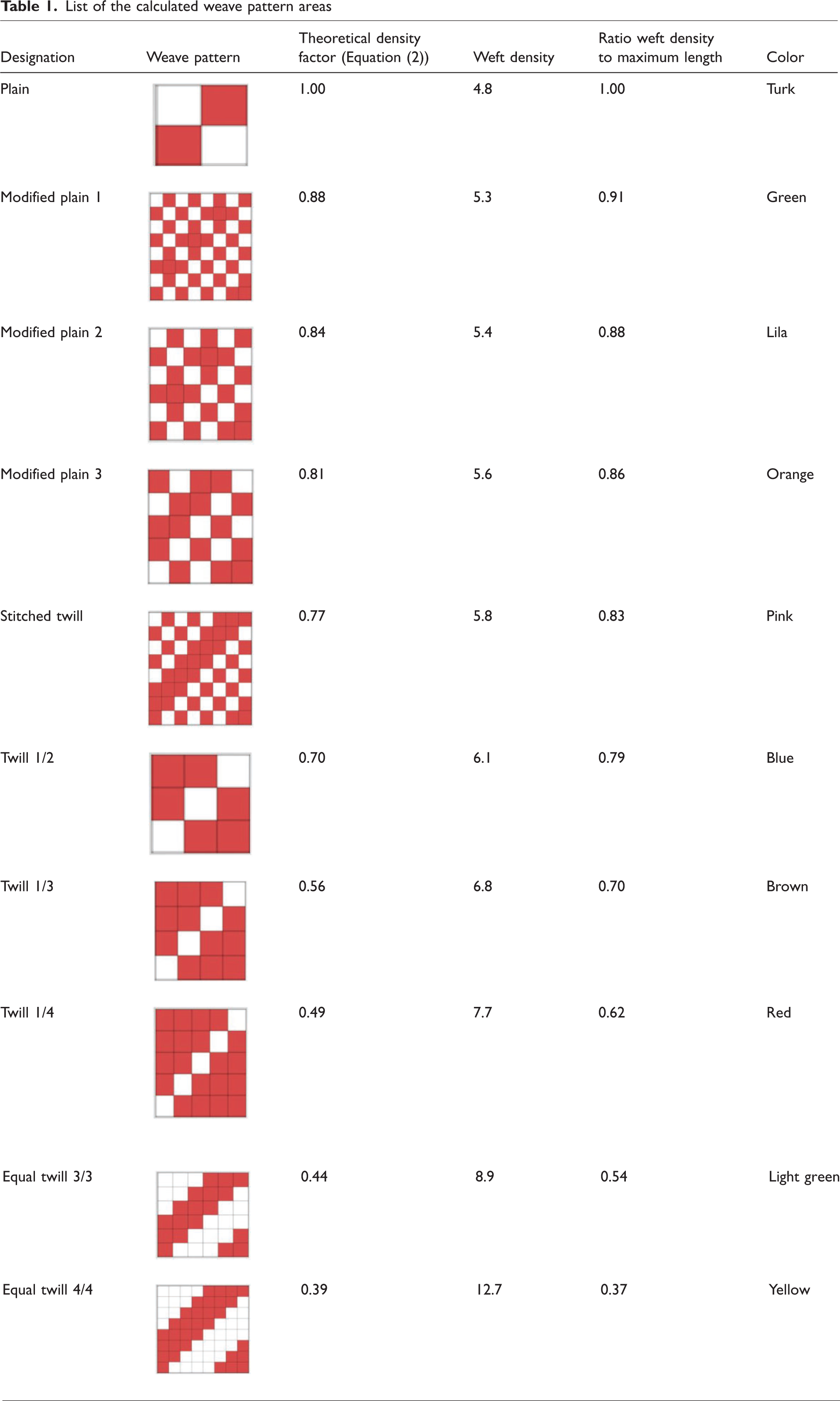
The arc lengths of the hemisphere were calculated using the smoothing spline algorithm, with a grid size of 36 in both the weft and warp directions. Prior to weaving, a selection of different weaves with varying theoretical density factors was made to generate the thread lengths. The courses of the virtual yarns have been adjusted by the developed optimization algorithm. Weft density calculations for each chosen weave pattern and the determination of the maximum crossing ratio were performed using Equation (7). This ratio was then assigned to the arc length ratio of the virtual warp yarns. The required weft densities were subsequently calculated based on the length ratios and their corresponding assigned weaves. The creation of the final weave pattern considered the pixel-to-length ratio to ensure accurate correspondence between the arc lengths of the hemisphere and the weave pattern. Figure 12 illustrates the calculation process for a selected warp thread, where the marked virtual warp thread demonstrates the calculation process and color assignment of the necessary weaves. In this specific area, variations in the length of the warp thread were generated by utilizing a combination of twill 1/3 and plain weave. The complete calculated weave pattern, providing the different arc lengths, is shown in Table 1. The colors of the binding areas go symmetrically from the center of the hemisphere to the edges. The image file was then imported into the EAT Design Scope software, where the appropriate weaves were assigned to individual color areas. Subsequently, a control file for the Jacquard machine was generated, enabling the weaving of the sample without the need for take-up. After production, the fabric was removed from the weaving machine and shaped to the final geometry. The successful creation of the hemisphere is illustrated in Figure 13.
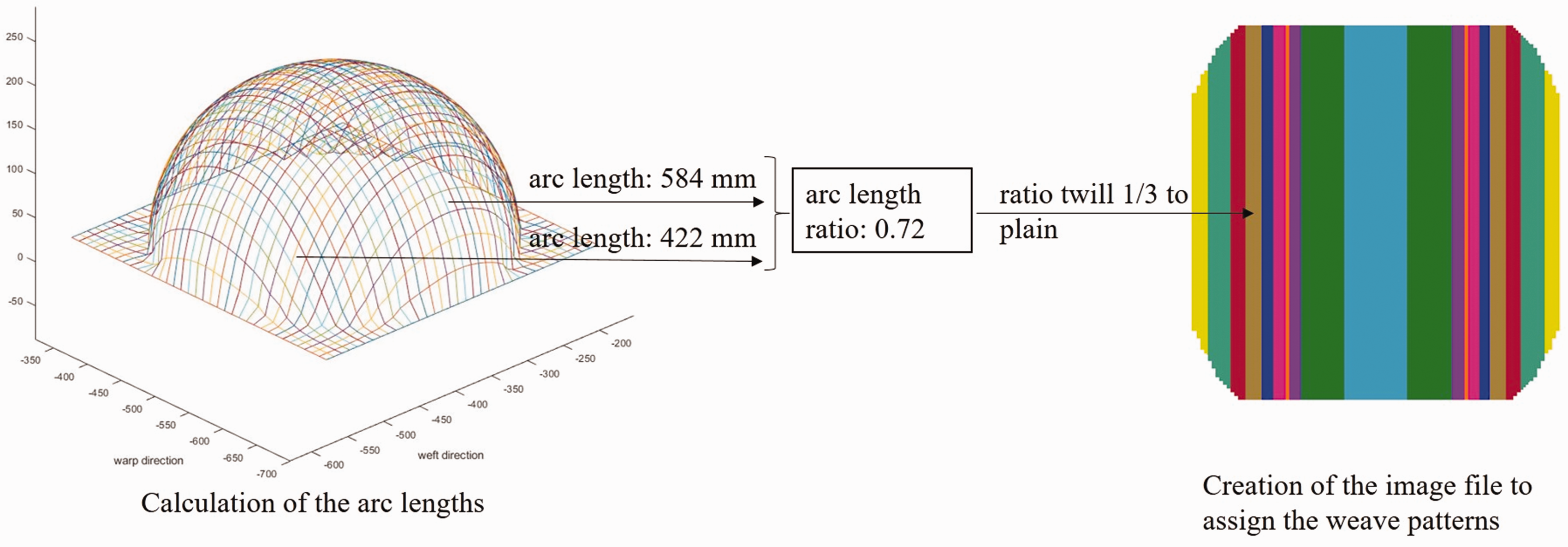
Processing of the calculation and creation of the image code of the different weave pattern areas.
List of the calculated weave pattern areas
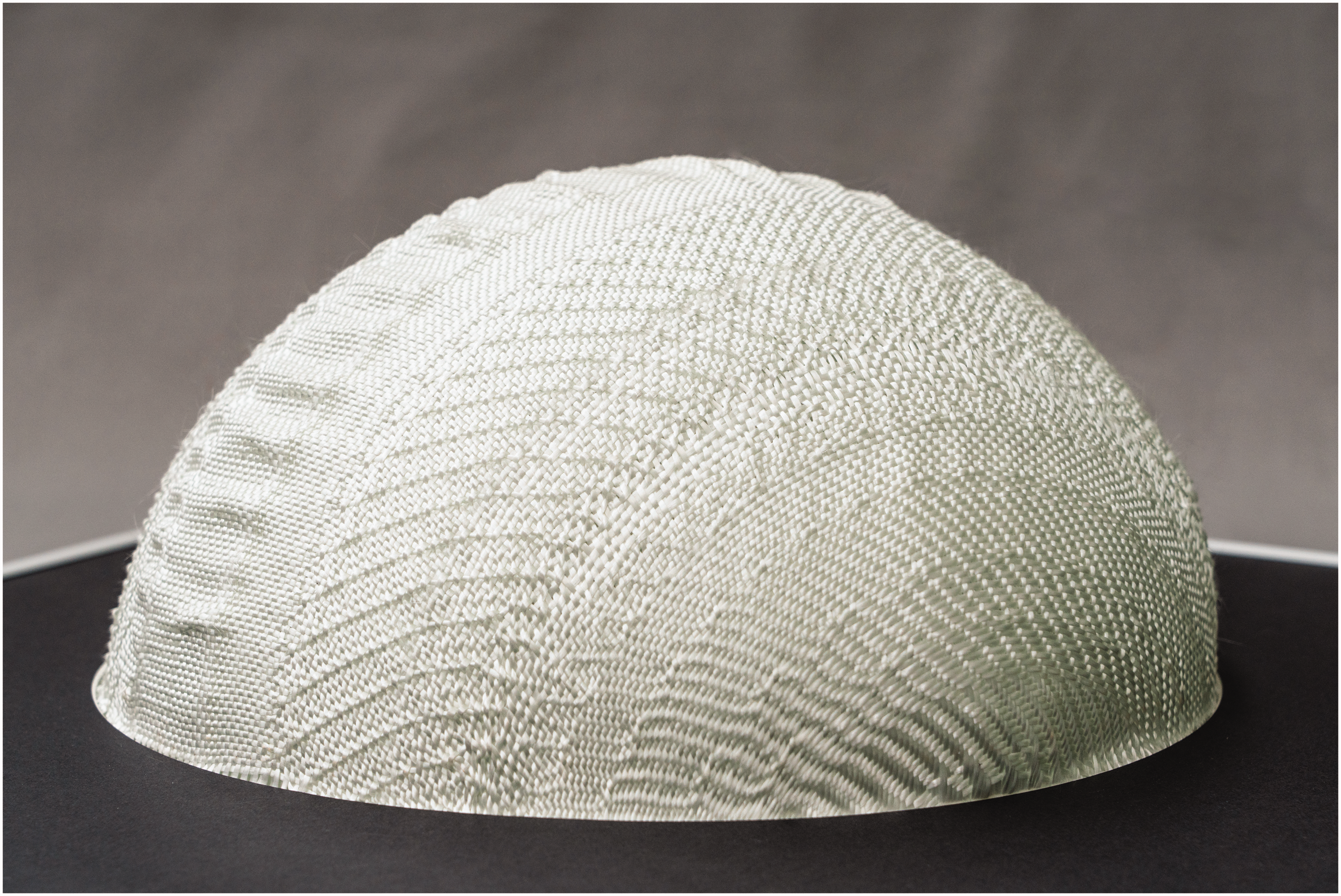
Woven hemisphere produced employing the novel retainer hook system.
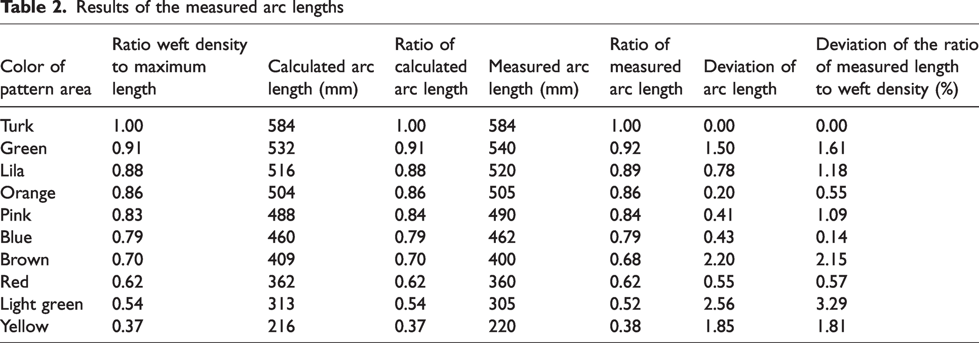
Verification of the geometric accuracy of the woven hemisphere: to evaluate the geometric accuracy of the woven hemisphere, a thorough investigation and analysis of the calculation steps were conducted. The focus of this analysis was on examining the different areas of the weave patterns. The computed arc lengths and their corresponding length ratios, relative to the maximum arc length determined by the program routine, were extracted. These length ratios were calculated based on the previously determined weft density ratios of the respective weave patterns within their designated areas.
Next, the arc lengths of the individual weave pattern areas were measured on the woven hemisphere, and the length ratios were calculated accordingly. The measured sheet lengths were then compared to the calculated sheet lengths, and the discrepancy between them was recorded. In addition, a comparison was made between the measured length ratios and the weft density ratios of the weaves. The analysis revealed that the measured arc lengths exhibited a maximum deviation of 2.56% from the computed arc lengths. Similarly, the maximum deviation between the length ratios and the weft density ratios amounted to 3.29% (refer to Table 2 for detailed results).
Results of the measured arc lengths
Conclusion
The production of three-dimensionally shaped 2D fabrics with near-net-shape characteristics offers significant advantages by directly achieving the required geometry without the need for fabric draping or cutting, resulting in reduced waste and process steps in the manufacturing of FRP. In this paper, a novel retainer hook technology for producing fabrics with spherical curvature by eliminating the take-up system of a weaving machine is developed, opening up new manufacturing possibilities to meet specific fabric requirements. This technology replaces the take-up mechanism of conventional weaving machines, allowing warp thread lengths to be woven into the fabric at varying lengths by manipulating the crossing points of warp and weft yarns across the fabric width.
The fundamental calculation methods necessary for the production of these spherical curvature woven fabrics were developed. This approach enables the determination of the appropriate weave arrangement to achieve the desired spherically curved shape. To translate the desired geometry into the control system of the weaving machine, the input geometry needs to be calculated and covered with virtual yarns. An iterative optimization algorithm was developed for this purpose, adjusting the course of the virtual yarns. By establishing the relationship between the weft density ratio of selected fabric weaves and the resulting length incorporation that can be achieved, the corresponding weave patterns were assigned to the previously calculated thread lengths, thereby generating the desired geometry. An equation specific to the thread material was devised to calculate the relationship between the weave-dependent density factor and the resulting weft density, facilitating the assignment of weaves to different warp lengths traversing the geometry's surface. These developed methods were implemented in a program routine that allows the calculation of the necessary control file for the specific weaving machine used.
The effectiveness of this approach was validated through the successful weaving of a hemisphere employing the novel retainer hook system. The achieved maximum deviation of 2.56% between the calculated inserted length differences of the warp yarns and the actual woven-in lengths confirms the accuracy of the method. These types of geometries can be used to manufacture composite components such as for an “antenna reflector structure.”
Nevertheless, there are limitations for the developed technology. These include a maximum production speed of 200 wefts per minute and a limit on the curvatures that can be realized. So far, it is not possible to produce closed structures such as a sphere or curvatures with corners. Furthermore, the curvature is only generated by changing the warp yarn lengths, and there is a limitation of the neighboring weft densities. If the difference is too high, the area of the longer warp yarns will wrinkle. To achieve a higher geometrical variety, an active change of the weft thread length is also desirable. For this purpose, further research is needed, such as changing the warp thread density and thus weft thread length incorporation into the fabric. In addition, the different weaves in the fabrics result in different fiber distributions and thus mass per unit area. With regard to the use of the fabrics in composite applications, a uniform basis weight is to be aimed for. For the production of these fabrics with the technology described in this paper, further developments are necessary. New concepts, such as the introduction of partial wefts, may be promising for this purpose. Further development of the calculation algorithms is required to produce shapes with even or wrinkle-free curvatures. This entails exploring novel approaches, including the development of a calculation solution for independent control of the weaving machine without relying solely on traditional weave patterns. In addition, new methods for arranging the geometry in relation to the weaving plane need to be devised, enabling the exploration of new woven structures such as spiral weaves or two-layer weaves with distinct warp thread lengths in each layer.
Footnotes
Declaration of conflicting interests
The author(s) declared no potential conflicts of interest with respect to the research, authorship, and/or publication of this article.
Funding
The authors disclosed receipt of the following financial support for the research, authorship, and/or publication of this article: This work was supported by the Federal Ministry for Economic Affairs and Climate Action (BMWK) through the AiF (German Federation of Industrial Research Associations eV) based on a decision taken by the German Bundestag. The research project was carried out in the framework of the industrial collective research programme (IGF no. 19805 BR).