
Abstract
Concrete canvas has taken attention for their rapidly deployable hardened characteristic property in civil engineering. However, the drying shrinkage of concrete canvas has not been addressed yet in the literatures. In this study, a theoretical model was presented for studying influences of 3D spacer fabric on drying shrinkage of concrete canvas. The model was based on assumption that drying shrinkage restraint provided by 3D spacer fabric is joint action of each component of 3D spacer fabric separately. To calibrate this model, the drying shrinkage of two concrete canvases reinforced by PET-based 3D spacer fabric with one solid outer textile substrate was experimented. Moreover, a simplified expression of maximum tensile stress generated in the matrix of both concrete canvases was obtained for evaluating their risk of drying shrinkage-induced cracking. The results showed that drying shrinkage strain of concrete canvas samples became lower due to the restraint provided by 3D spacer fabric and a satisfactory correlation between model predictions and experimental results was found at later age. For both concrete canvases, a greater restraint was found in warp direction, thereby resulting in a larger tensile stress generated in the matrix. Furthermore, the restraint on the drying shrinkage of concrete canvas was provided mostly by spacer yarns and thereby it contributed to the most of maximum tensile stress generated in the matrix of concrete canvas.
Keywords
Introduction
Recently, an increasing interest occurred in the use of 3D spacer fabric as novel component reinforcement for cement-based composite materials [1–3]. 3D spacer fabric, composed by two components of outer textile substrates and spacer yarns, is a special type of textile with 3D yarn architecture and 3D textile architecture [4]. Due to the beneficial structure of an armature system of highly oriented yarns, 3D spacer fabric has been shown to exhibit a superior behavior as it can be easily placed in a mold and impregnated to its whole depth by cement-based matrix in one step [5]. Meanwhile, 3D spacer fabric can be used for producing concrete elements with reinforcing yarns in three directions and defined positioning of the two outer substrates [4]. 3D spacer fabric has been applied successfully in civil engineering, such as prefabricated wall panels and shell concrete members [1,2].
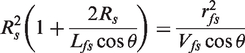
In addition, a more attractive type of cementitious composite, i.e. concrete canvas (CC), is manufactured through 3D spacer fabric [6–8]. The significant difference between CC and conventional 3D spacer fabric reinforced cementitious composites is the preparation process. Before set of the cement powder, CC is a flexible 3D spacer fabric impregnated with cement powder that can cover the surface of arbitrary structure or element like a soft cloth, whatever its shape. Then, one just needs to spray or add water from the top surface of the CC for construction. Once set, a thin composite layer, that is durable, water-resistant and fire resistant, forms. Han’s work [7,8] demonstrated that compared with the matrix without fabric, 3D spacer fabric provided an efficient reinforcement on both compressive and tensile behavior of the CC. Thus, CC can be quickly, efficiently and widely used as a structural element to form a cover for prefabricated shelters, paths for vehicles or for pedestrians, or a protective layer for pipes, linings, etc. [6].
It is well known that cracking in cementitious composites significantly influences their service life. In addition to the action of external load, the main reason for initial crack formation in the cementitious composites structures is partially attributed to its drying shrinkage [9,10], which is particularly significant in the case of thin-wall slab element. It is also recognized that fibers in cementitious composites provide significant restraint on their drying shrinkage, which has been comprehensively studied in the literatures [11–13]. In fact, the restraint provided by fibers is mainly realized by bonding strength through the contact interface between fibers and matrix [14,15]. Once cement matrix undergoes shrinkage, fibers are subjected to compressive stress whereas cement matrix is subjected to tensile stress due to the shear stress produced on their contact interface. In the case of CC, both spacer yarns and outer textile substrates of the 3D spacer fabric can provide restraint on its drying shrinkage, and the influence of 3D spacer fabric should be investigated thoroughly. However, to the author’s current knowledge, the drying shrinkage of CC, one of most concentrated factors, has not been addressed yet.
This study aimed to investigate the influence of 3D spacer fabric on the drying shrinkage of CC. A theoretical model of the drying shrinkage of CC was presented. The drying shrinkage of two CCs reinforced by PET-based 3D spacer fabric with one solid outer textile substrate was tested to verify the rationality of this model. Contribution of the restraint provided by each component of 3D spacer fabric to the drying shrinkage of CCs was compared. Furthermore, an expression of maximum tensile stress generated in the matrix of CC was applied to evaluate the risk of drying shrinkage-induced cracking in CC.
Description of drying shrinkage model
As depicted in Figure 1, a special 3D spacer fabric with 15-mm thickness, designed for CC, was produced on a double needle bar Rachel machine. Since cement powder is required to be easily impregnated into 3D spacer fabric and kept from leaking out of it, one of the two outer textile substrates of 3D spacer fabric was knitted into mesh fabric (MF) and the other was knitted into solid fabric (SF). Three characteristic directions are warp, weft and through-the-thickness directions. The warp direction is in the lengthwise and weft direction is in the fabric cross direction. The warp yarns in the warp direction were inserted into stitches and assembled together with weft yarns in the weft direction, and then a grid net was produced and meshes in the net can be knitted in various shapes. Additionally, oriented spacer yarns were inserted into the structure. The warp yarns and weft yarns were usually in a multifilament and twisted form. Obviously, the performance of 3D spacer fabric is anisotropy due to its unique architecture. As a result, the drying shrinkage behavior of CC must be different along various directions.
Structures of 3D spacer fabric designed for CC application.
The initial cracking point strain of CC subjected to uniaxial static strain was around 1.2*10−2–3.9*10−2. The previous works showed that the magnitude of drying shrinkage strain of CC was lower than 1*10−3 [16]. It is lower than the initial cracking strain. In other words, the inter-anchorage effect of spacer yarns with outer textile substrates was not reflected yet during the drying shrinkage period [7]. Therefore, it is assumed that the restraint provided by 3D spacer fabric on the drying shrinkage of CC came from its two components separately, i.e. outer textiles substrates and spacer yarns, as shown in Figure 1. As it was a thin-wall and anisotropic element, this study mainly focused on the drying shrinkage of CC in the warp and weft directions.
If only the spacer yarns was focused, a certain degree of symmetrical deflection of spacer yarns existed in the warp direction, as depicted in Figure 1(a), due to the gravity effect of spacer yarns and outer textile substrates. Generally, the orientation distribution of spacer yarns required a three-dimensional description as shown in Figure 2(a). Due to the symmetrical structure, the “V-shape” spacer yarns can be simplicity as a straight fiber by two steps as shown in Figure 2(a) for the sake of simplicity of calculation [17]. In Figure 2(a), the X-, Y- and Z-axes indicated the direction of warp, weft and through-the-thickness of 3D spacer fabric, respectively. Here, as shown in Figure 2(b) and (c), the projected orientation angle and projected length of spacer yarns in the X-Z plane along warp direction and Y-Z plane along weft direction were considered directly. The projected orientation can be calculated as following
Simplified modeling of spacer yarns of 3D spacer fabric.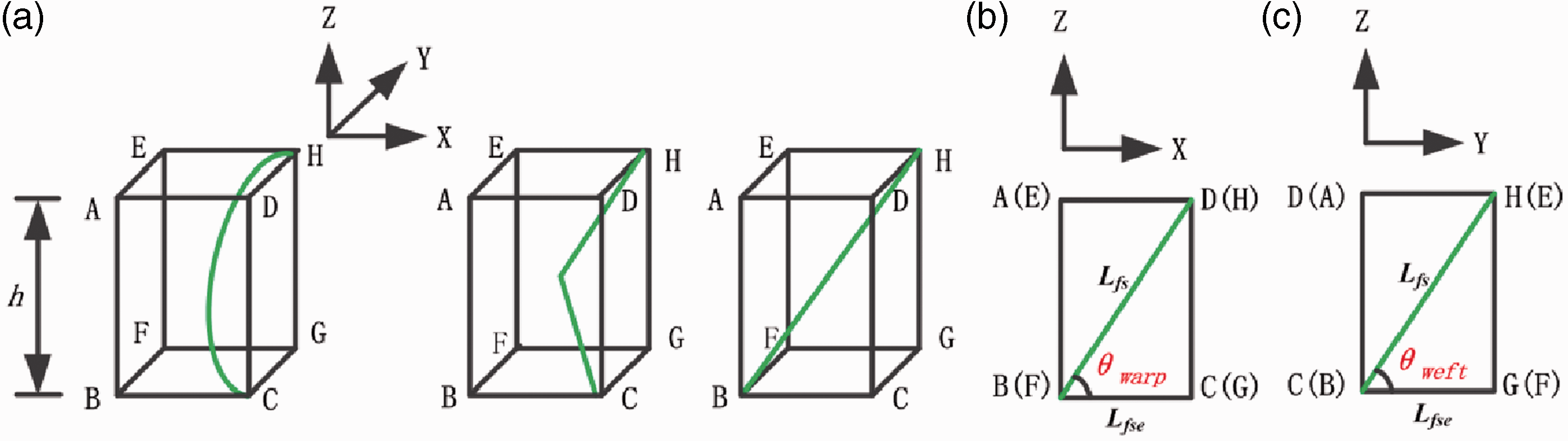

The shrinkage of matrix in any direction can be considered to be restrained by an aligned fiber of effective length parallel to the direction of the shrinkage strain. This is due to the tendency of the matrix to slide past the fiber during shrinkage, the fiber in turn providing restraint to the sliding action through the fiber-matrix interfacial bond strength [14]. Therefore, it was assumed that the restraint provided by spacer yarns with projected length Lfs and volume content Vfs in CC was equivalent to the restraint in an idealized composite with aligned spacer yarn distribution, effective spacer yarn length Lfse and spacer yarn spacing 2Rs, as given in Figure 3(a) [18]. The effective spacer yarn length Lfse of spacer yarns along warp or weft directions was given by
Schematic diagram of restraint provided by spacer yarns. (a) Equivalent element resulted from transformation of spacer yarns and (b) enlarged representative cylinder.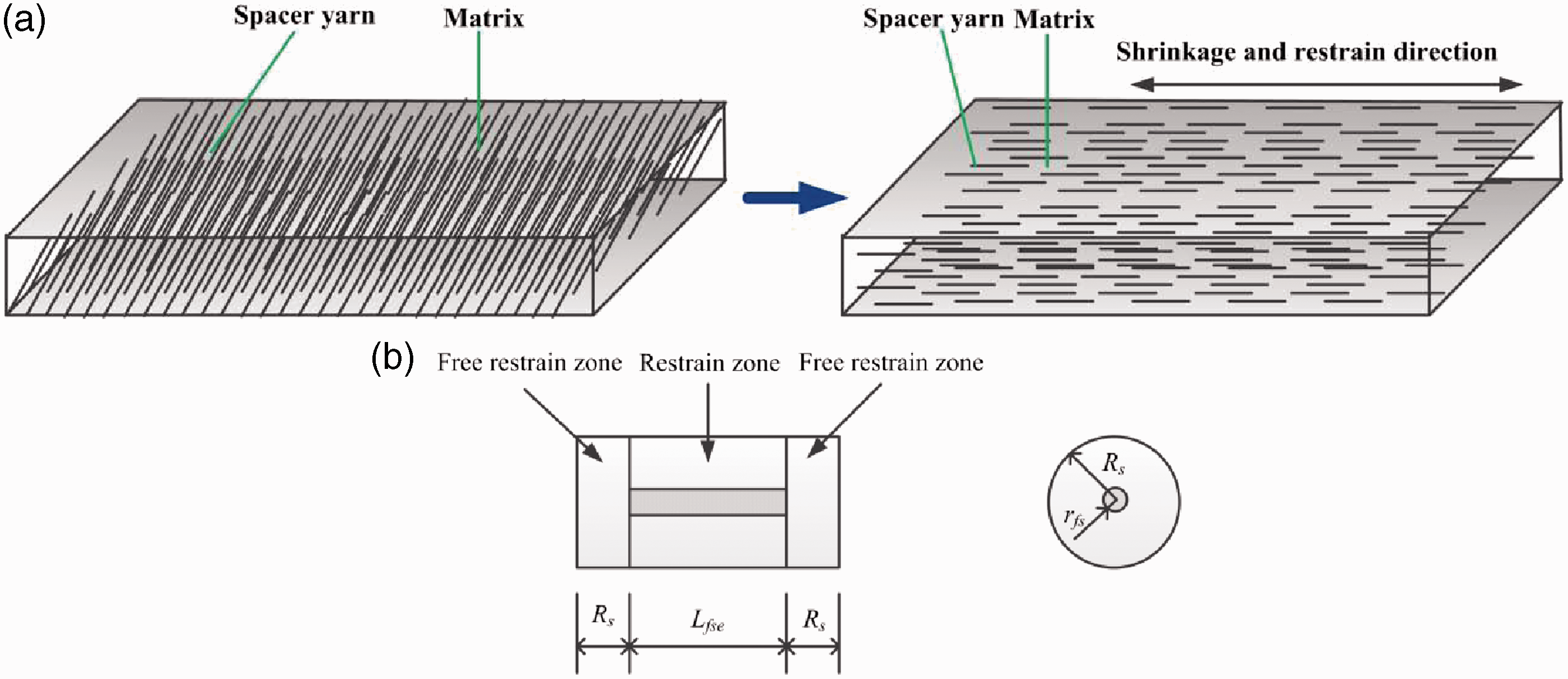

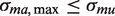
The spacer yarn spacing 2Rs could be solved through the representative cylinder with radius Rs and length (Lfse + 2Rs) isolated from CC, as shown in Figure 3(b). Based on the assumption that the total volume of CC was equal to the sum of all individual cylinder volumes, the spacer yarn spacing 2Rs along shrinkage direction could be calculated as following
Thus, the restraint provided by spacer yarns on the drying shrinkage of CC could be calculated through the representative volume element with a single spacer yarn in center, as shown in Figure 3(b) [18]. In Figure 3(b), the shrinkage of cylinder cement matrix adjacent to the spacer yarn was considered to be influenced by the spacer yarn, whereas the left and the right parts of length Rs each were assumed to be free of its influence because the contact area at the tip of fiber is too small for the matrix to transfer any significant force in the fiber. Moreover, the tensile stress exerted on cement matrix was a function of location within restrain zone. Accordingly, the expression of free drying shrinkage of CC under the work of spacer yarns along shrinkage direction was given by [18,19]

According to Zhang et al. [18,19], the tensile stress σmas could be solved from shear-lag theory based on several simplifying assumptions: (1) the matrix and reinforcing spacer yarns are both elastic materials; (2) the interface between the matrix and spacer yarns is infinitesimally thin; (3) there is no slip between the spacer yarns and the matrix at the interface; (4) the shrinkage strain in matrix ɛm, at a distance Rs from the reinforcement, is equal to the free shrinkage of the matrix. Therefore, the tensile stress σmas was given by


Substituting σmas in equation (4) with equation (5), the ɛts could be obtained as


Similarly, the restraint provided by outer textile substrates could be calculated by the same procedure. The interaction between warp yarns and weft yarns was ignored due to the small drying shrinkage strain level. In addition, the restraint provided by SF was excluded. This was attributed to the fact that the SF was exposed on the surface of hardened cement matrix rather than anchored into matrix. Therefore, by combing the restraint provided by MF and spacer yarns, the drying shrinkage of CC along warp or weft directions can be expressed as

Equation (9) provided a general relationship between the drying shrinkage strains of CC along warp or weft directions under the interaction of 3D spacer fabric with pure matrix. Equation (9) revealed that the drying shrinkage strain of CC is less than that of pure matrix and it is influenced by the properties of spacer yarn (including spacer yarn length, radius, volume content, orientation angle and elastic modulus), the warp/weft yarn (including warp/weft yarn length, radius, volume content, orientation angle and elastic modulus) and matrix (including the drying shrinkage behavior and the corresponding elastic modulus).
As the hydration goes on, the matrix of CC was subjected to tensile stress due to the restraint provided by 3D spacer fabric. As discussed above, the total tensile stress generated in the matrix of CC can be calculated by equation (10)

It was found from equation (10) that time-dependent tensile stress generated in matrix is closely related to the drying shrinkage of pure matrix, as well as to the restraint provided by 3D spacer fabric. In addition, it also should be noted that the drying shrinkage-induced maximum tensile stress generated in matrix is critical for the crack ignition and propagation in the CC slab when comparing to the ultimate tensile strength of matrix.
Experimental verification
To verify the rationality of the model given in equation (9), the drying shrinkage experiments of two CC reinforced by PET-based 3D spacer fabric with one solid outer textile substrate and pure matrix were conducted. Also, the tensile elastic modulus of pure matrix was tested as one input parameter.
Raw materials
Structure and view of 3D spacer fabrics.

Properties of components of 3D spacer fabrics.

The value is the mean diameter of multifilament.
Related input parameters of 3D spacer fabrics.

Left and right side of the slash are volume fraction of warp yarns and weft yarns of MF, respectively.
Left and right side of the slash are orientation angle of warp yarns and weft yarns of MF, respectively.
Left and right side of the slash are length of warp yarns and weft yarns of MF, respectively.
Mineralogical and chemical compositions of sulphoaluminate cement (CSA) and anhydrite.

Mixture proportion of matrix (kg/m3).

Specimens preparation and characterization
The preparation was conducted at temperature of 25℃ and relative humidity of 75%. Firstly, powder mixture with the designed proportion was poured into a Thunderbird ARM-02 mixer and stirred for 10 minutes at 94 r/min. The mixed powder was then gradually placed and vibrated into the mold containing 3D spacer fabric of 160 mm × 40 mm × 15 mm until the 3D spacer fabric was compactly impregnated with powder. For the purpose of comparison, the unreinforced control samples (CTRL) with the same sizes were also prepared in the same way. To obtain the tensile elastic modulus of pure matrix, a plastic mold with dimensions of 400 mm × 100 mm × 15 mm was adopted. Finally, tap water at the temperature of 24.3℃ was sprayed onto the surface of CC sample until the water/binder ratio reached 0.45. After final setting the specimens were demolded and cured at the temperature of 25 ± 2℃ and relative humidity of 65 ± 5%. According to the difference in the type of 3D spacer fabrics, the CC samples were labeled N1-CC and N2-CC, respectively.
The drying shrinkage of control samples and CC samples in warp and weft directions were measured using contraction rack and dial gauge as shown in Figure 4, according to Chinese specification JC/T 603-2004 [20]. The initial length of the samples was measured at 3 hours after water-spraying and regular length measurements were made thereafter up to 90 days age. After different curing ages (3 d, 7 d, 14 d, 28 d, 90 d), the tensile elastic modulus of pure matrix were tested by an uniaxial tensile test machine (CMT 5105) equipped with a 100 kN load cell according to Chinese national standard GB/T 50081-2002 [21], as shown in Figure 5. The strain was acquired by a dynamic data acquisition instrument (TMR-7200). Three parallel samples were tested for each point. The average values and the corresponding standard deviation were presented. The detail on the influence of geometric pattern of 3D spacer fabric on tensile behavior of CC can be found in Ref. [7].
Set-up for drying shrinkage tests. Set up for tensile elastic modulus tests of pure matrix.

Experimental results
The drying shrinkage strain versus curing age curves of CC and control samples are shown in Figure 6. In all cases, the drying shrinkage strain increases with curing age and develops fast within 10 curing days. After 30 curing days, the drying shrinkage curves are prone to flatten. This is consistent with the trend of compressive strengths development, as shown in Figure 7 [7,8]. Compared to the control samples, the drying shrinkage strain of CC samples becomes lower due to the restraint provided by 3D spacer fabric. In addition, the drying shrinkage of CC samples in warp direction is less than that in weft direction. It revealed that the restraint provided by 3D spacer fabric in warp direction is stronger than that in weft direction, which is consistent with the result of mechanical anisotropy of CC samples [8]. This is attributed to the layout pattern of spacer yarn as shown in Table 1; the orientation angle of spacer yarn in the warp direction is lower than that in the weft direction after transforming as shown in Table 3. Consequently, a greater restraint was obtained with a lower orientation angle of spacer yarn as described in equation (9). In each direction, the drying shrinkage strain of N1-CCs is less than that of N2-CCs, where the mostly impact factors shown in equation (9) are also the projected orientation angles and projected length of spacer yarn and warp/weft yarn. Due to the lower projected orientation angle and larger projected length of spacer yarn and warp/weft yarn as presented in Table 3, a greater restraint was obtained for N1-CCs and then resulting in a less drying shrinkage strain. Figure 8 shows the tensile elastic modulus of pure matrix at different curing ages. Similar to drying shrinkage of CCs, it also increases with curing age and develops from rapidly to gently after 10 days.
Experimental results of drying shrinkage of CCs and control samples. Time-dependent compressive strength of CC sample [7]. Experimental results of tensile elastic modulus of pure matrix.


As the drying shrinkage strain ɛm and tensile elastic modulus Em of pure matrix were two key input parameters for the presented drying shrinkage model, it should obtain the expressions of ɛm and Em, and they could be acquired by fitting the experimental data. The famous models of drying shrinkage of cement matrix in the literatures included CEB-FIP model, ACI model and BP model [22]. The CEB-FIP model, as shown in equation (11), is adopted in numerous concrete codes across the world and is valid for concrete with a compressive strength between 12 and 80 MPa. The BP model, as shown in equation (12), is semi-empirical but the most powerful one which considers almost every parameter affecting the shrinkage behavior. The ACI model, as shown in equation (13), was one of the most simple and the most accurate in predicting time-dependent strains [23]


Therefore, the ACI model was chosen to fit the experimental data. Referring to the ACI 209R-92 shrinkage model [24], the fitting result of ɛm was expressed as

Similarly, the fitting result of tensile modulus Em was expressed as

Model verification
Substituting the relevant parameters in Table 3, the expressions of free drying shrinkage strain of control samples, and tensile elastic modulus of pure matrix into the equation (9), would theoretically obtain the drying shrinkage strain of CCs in the warp and weft directions. The comparisons between model predictions and experimental results are shown in Figure 9. It can be seen that theoretical predictions are in satisfactory agreement with experimental results at later age, except the weft direction of N1-CCs. However, in the weft direction of N1-CCs, a good agreement between theoretical prediction and experimental result is found when ignoring the restraint contributed from warp/weft yarns, as shown in Figure 9(a). It revealed that the warp/weft yarns of MF do not provide restraint on the drying shrinkage of N1-CCs in the weft direction. The reason may be attributed to the form of weft yarns. As shown in Table 1, the weft yarns of MF of N1 are in straight form rather than twisted form. Generally, the warp/weft yarns in straight form mainly improved the bonding effect between outer textile substrates and cement matrix. This made their rigidity rather low when they are subjected to compressive stress [25]. By comparing the contribution of the restraint provided by each component of 3D spacer fabric to the drying shrinkage of both CC samples, as shown in Figure 9, it can be seen that the restraint on their drying shrinkage is provided mostly by spacer yarns. This is attributed to its larger volume faction and higher Young’s modulus.
Comparisons of model predictions with experimental results of CCs. (a) N1-CC and (b) N2-CC. The double arrow lines and corresponding values represent the fraction of restraint provided by spacer yarns.
Risk evaluation of drying shrinkage-induced cracking
Due to the restraint provided by 3D spacer fabric, the matrix of CC was subjected to tensile stress when it shrunk. Once the maximum tensile stress generated in its matrix, calculated by equation (10), exceeded the ultimate tensile stress of the matrix, crack would occur. Therefore, the critical criterion for cracking can be expressed as
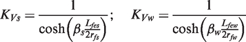
In order to evaluate the risk of drying shrinkage-induced cracking of CC samples, it should first derive the expression of σmu. Following the similar procedure of deriving the tensile elastic modulus of matrix, as shown in equation (15), the time-dependent ultimate tensile strength of matrix can be expressed as

In the equation (10), when dσma/dx = 0, that is xs = Lfes/2 and xw = Lfew/2. Thus, the drying shrinkage-induced maximum tensile stress generated in matrix of CC along warp or weft directions can be given by

Here, KVs and KVt are two influence factors depending on yarn properties, which are closely related to the volume fraction, length, radius and orientation angle of yarns. For the components of 3D spacer fabric in this study, the contribution of these two influence factors to the σma,max can be negligible, as demonstrated in Figure 10, which are applied with components parameters of N2.
Influence factor KV versus curing age for N2.
Therefore, equation (18) could be simplified as


The comparisons between the drying shrinkage-induced maximum tensile stress generated in matrix, calculated from equation (20), and ultimate tensile strength of the matrix are shown Figure 11. It can be seen from Figure 11 that the maximum tensile stress generated in matrix of both CC samples is much lower than the ultimate tensile strength of the matrix during curing, regardless of shrinkage directions. It indicated that crack induced by the drying shrinkage does not occur in both the CC samples during their service life. In addition, it should be noted that the maximum tensile stress generated in matrix in the warp direction is higher than that in the weft direction, which attributed to the greater restraint provided by 3D spacer fabric in the warp direction. Therefore, it was critical to prevent drying shrinkage-induced cracking by introducing fibers to matrix. In each direction, the maximum tensile stress generated in the matrix of N2-CCs is lower than that of N1-CCs, due to the lager projected orientation angles as well as to smaller projected lengths of both spacer yarns and warp/weft yarns of N2. As shown in Figure 11, the maximum tensile stress generated in the matrix of both CC samples was also contributed mostly by spacer yarns, due to its greater restraint on drying shrinkage.
Analysis on risk of drying shrinkage-induced cracking of CCs. The double arrow lines and corresponding values represent the fraction of maximum tensile stress contributed by spacer yarns.
Conclusions
An analytical model is presented for studying the influence of 3D spacer fabric on drying shrinkage of CC samples. A satisfactory correlation between the model predictions and experimental results is found at later age. Due to the introduction of 3D spacer fabric, the drying shrinkage strain of CC samples becomes lower than the control samples. A greater restraint is found in warp direction due to the smaller orientation angle. The restraint on the drying shrinkage of both CC samples is provided mostly by spacer yarns, which is attributed to its larger volume faction and higher Young’s modulus. Furthermore, a simplified expression of drying shrinkage-induced maximum tensile stress generated in the matrix is derived for evaluating the risk of cracking for both CC samples. A larger drying shrinkage-induced maximum tensile stress generated in matrix is found in warp direction due to the greater restraint. Moreover, spacer yarns contribute to the most of maximum tensile stress generated in the matrix of CCs.
Footnotes
Acknowledgement
The authors gratefully acknowledge financial support from the Architectural Engineering Institute of the General Logistic Department of P.L.A.
Declaration of Conflicting Interests
The author(s) declared no potential conflicts of interest with respect to the research, authorship, and/or publication of this article.
Funding
The author(s) received no financial support for the research, authorship, and/or publication of this article.