
Abstract
Due to the increasing importance of natural fiber reinforced polymer composites, a large number of papers published about fabrication of these materials, but yet the secondary manufacturing performance knowledge of such materials is rather limited. Understanding cutting performance of a novel natural fiber (cotton) reinforced polymer composite is the primary interest of this work. In the first part of the study, suitable cutting tool geometry was designated through milling tests and the results of cutting force, burr formation, and chip morphology. One flute left helix WC (Tungsten Carbide) tool was the most suitable tool geometry for cotton-fiber reinforced polymer milling. The optimum cutting parameters were selected with the designed quantitative scoring procedure for combined evaluation of cutting force and burr formation results. According to the evaluation system, the optimum cutting parameters were found as 25 m/min cutting speed and 200 mm/min feed rate. Three form of burr which are roll-over, poisson and entrance burr, and short ribbon shape chips with linty look were observed due to the embedded cotton fibers in LDPE matrix. At the end of the study, the benchmarking cutting force tests were conducted with pure low density polyethylene material and results compared with the cotton-fiber reinforced polymer.
Introduction
Nowadays, the low carbon footprint products and their manufacturing techniques have been receiving a great deal of attention due to the growing environmental consciousness and regulations in the whole world. The natural fiber composites have one of the lowest carbon footprint engineering materials for many engineering solutions for automotive, packaging, and construction industries. Hitherto, some waste natural fibers such as paper, nut, ganja, and cotton were used as a reinforcement element in natural fiber composite structures in many studies [1–6]. In general, the natural reinforcement elements are used in composite structure to minimize the synthetic polymer usage, reduce cost, and of course increase strength. Thus, utilization of natural waste in these products is going to be very beneficial in both manufacturing economy and environmental awareness.
Most of the polymer matrix products are the results of net shape or near net shape manufacturing processes, such as plastic injection or thermo forming methods. However, machining in polymer matrix composites is sometimes an inevitable process to remove excess material by milling or drilling operations for dimensional tolerance and assembly requirements, respectively [7]. These processes require study about burr formation, chip formation, cutting forces, gumming, and burning of polymeric materials during machining [8–12]. Machining of polymer base materials is significantly different from machining of conventional metals in many respects. The relationship between the machinability of polymeric materials and its properties is very complicated because of their viscoelastic behaviors [8]. Also low Young’s modulus, low thermal conductivity, and low melting point of polymeric materials make polymeric material machining a big challenge [9]. Because of their low thermal conductivity and melting point, any heat generation during machining process cannot be dissipated by conduction which causes the material to overheat rapidly, get soften, and stick to tool. A large amount of research has been carried out on the machining of thermosetting matrix composites, but the thermoplastic matrix composites related studies are very limited. Besides, no fundamental theories for their cutting characteristics have been established yet. One of the machinability studies on thermoplastic matrix composite material has been performed by Davim et al. on the machinability of glass reinforced Polyether ether ketone (PEEK) composites by response surface methodology [13].
They stated that the minimum cutting power was obtained when the cutting speed and feed rate were lower. However, the feed rate would be high in order to get minimal cutting speed and also there were no relations between cutting speed and specific cutting force [14].
In this study, low density polyethylene (LDPE) is reinforced with waste natural cotton fibers. The potential usage areas of cotton fiber reinforced polymer (cotton-FRP) material are garden furniture, garbage bins, park playground equipment, and the interior automotive trimming parts like lower surface of the car baggage.
The main aim of this study is to get better understanding on the cotton-FRP material machinability by the help of cutting forces, burr formation, and chip morphology analysis. Selection of the best cutting tool geometry among the commercially available cutting tool for cotton-FRP is one of the other goal of this study.
Experimental procedure
The plate shape recycled composite material was used as the workpiece material in this study. The matrix material of the workpiece was a LDPE and reinforcing element was waste cotton fibers (25 wt%). The fabrication process cycle of the workpiece material is shown in Figure 1. First, the small pieces (15 mm × 15 mm) of waste cotton fabrics and pure LDPE granules were fed into the custom-made single screw recycling extruder machine at the preset percentages and then the outset (term is used as nonshredded composite) composite plate was obtained. Following these steps, outset plate was fragmented by shredder to obtain composite granules including LDPE and mixture of cotton yarn and fabrics. The newly acquired composite granules were once again extruded and first “reprocessed plate” was being produced. This cycle of process was repeated six times and mechanical properties evaluated for selection purpose.
Manufacturing processes of recycled cotton-FRP.
The effect of reprocessing on the elastic modulus, tensile strength, and impact strength of cotton-FRP [15].
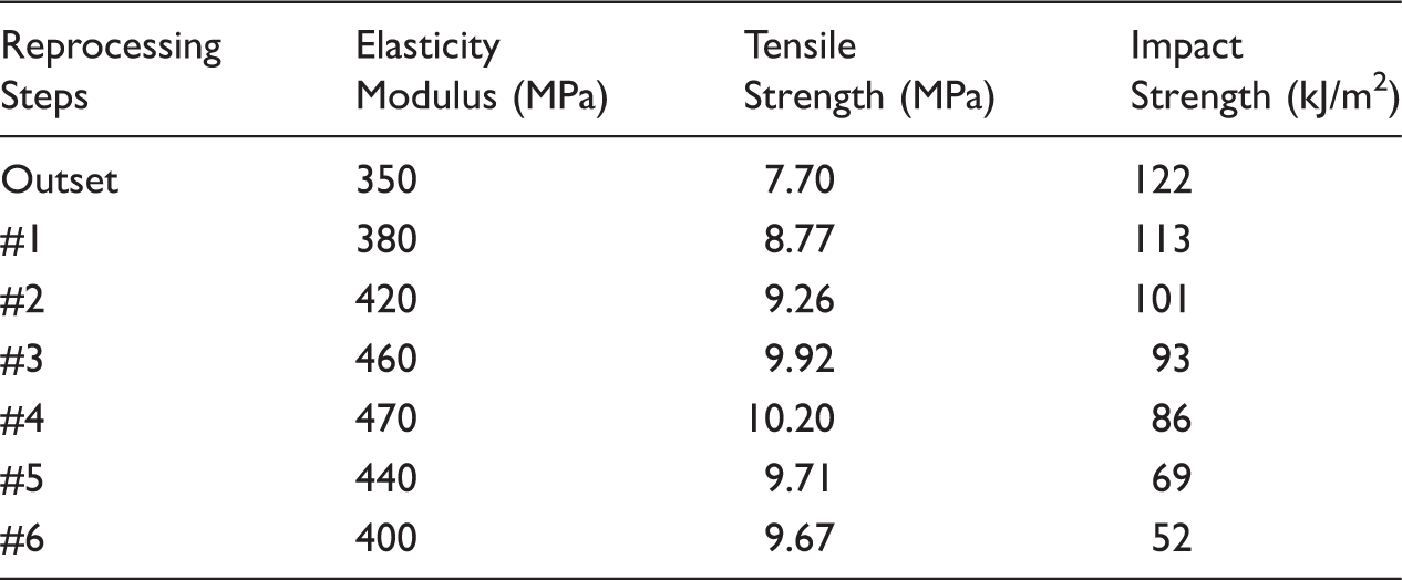
The highest value of elastic modulus, tensile strength, and acceptable impact strength were reached at the fourth reprocessing cycle. Thus, the product of the fourth reprocessing step plate was chosen as the workpiece material for machinability studies. After the fourth reprocessing step, cotton fabrics turned into cotton fibers and homogeneous fiber distribution was acquired within the LDPE matrix as shown in SEM image in Figure 2.
SEM micrograph of cotton-FRP at fourth reprocessed cycle.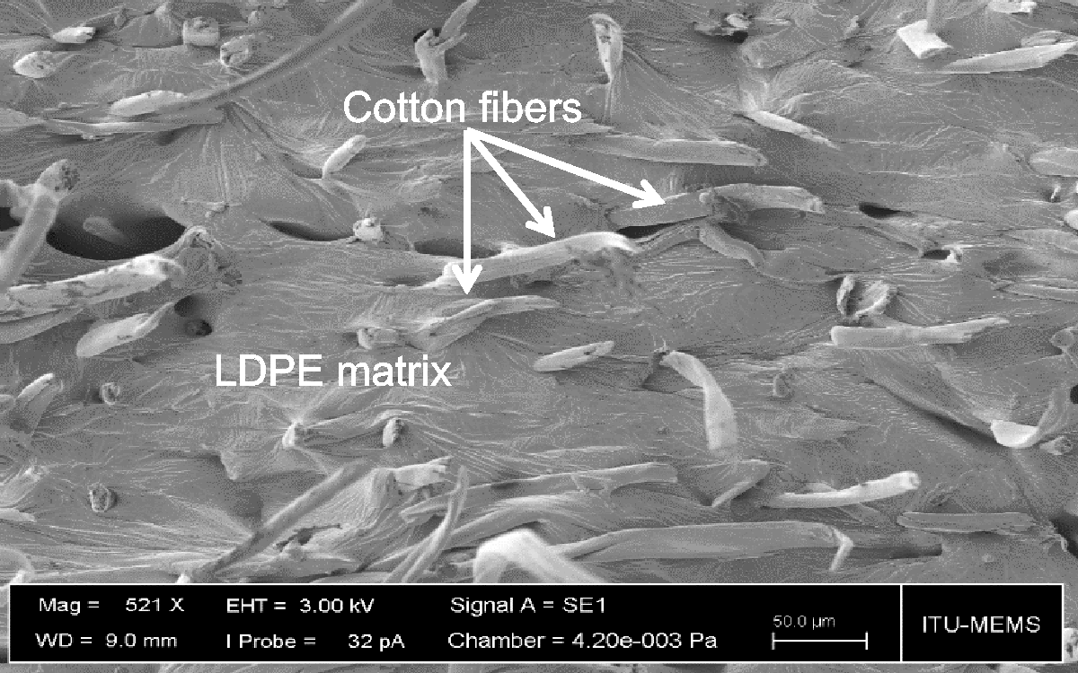
Comparison of the properties of cotton-FRP and other materials [10].
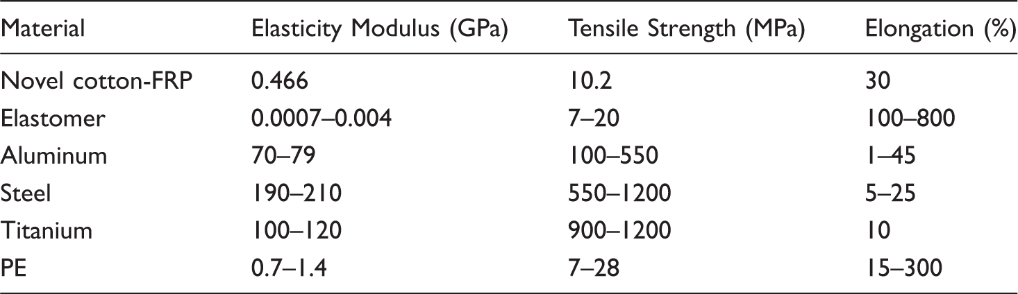
As it can be clearly seen in Table 2, the elastic modulus of the novel cotton-FRP composite is considerably low. By virtue of low modulus, excessive elastic deformation on the workpiece material may be expected during machining and preventive measures need to be developed [10]. Therefore, an eight slot steel template fixture was designed according to the test plan. The assembly of the workpiece, base plate, and the designed fixture onto the dynamometer is shown in Figure 3. Workpiece materials, cotton-FRP sheets, were placed between the base plate and fixture. While base mounted on the dynamometer, fixture, base, and workpiece material were fixed together with bolts for better rigidity. The size of the slots was selected according to the selected tool diameter and cutting length, the width of each slot is 12 mm and the length of each blind channel slot is 100 mm.
The test setup of cotton-FRP milling.
Tool pictures, geometries, and other details about uncoated HUFSCHMIED end mills.


Because there is no information about cotton-FRP material milling and remarkably limited systematic research about thermoplastic machining, in the first place proper cutting tool was selected for limited range of cutting parameters. Cutting tests for tool selection phase were performed for each tool at two different cutting speeds and feed rate levels. Tool preference criteria were the lowest resultant cutting force, less burr formation, and better chip morphology results. After tool selection phase, the cutting parameters were broadened to determine the suitable cutting speed and feed rate couples for cotton-FRP milling. Results were evaluated according to the cutting force, burr formation, and chip morphology. Finally, optimum cutting parameter and selected tool were used to cut pure LDPE material to benchmark results of cotton-FRP machinability.
Results
Tool selection phase results
Selected cutting parameters.

Force results
Cutting forces were evaluated by comparing the resultant forces calculated according to the following equation of Merchant’s approach
The maximum resultant forces for each cutting tool.

The highest cutting force value was measured as 95 N, with pyramid tooth tool (2FLU-PYR) at the low cutting speed (25 m/min) and high feed rate (200 mm/min). This is the worst cutting condition and tool geometry for Cotton-FRP milling. Recorded cutting force values for each tool in time domain is given in Figure 5 for six revolution periods. Pyramid tooth tool is specified as the “burr free tool” on composite milling by vendors [16]. Due to the almost no flute for chip evacuation and higher feed rate, dust type chips were formed and adhered on the tool tip. Similar result was also observed in lower feed rate (50 mm/min). For the same tool with high cutting speed condition, the chips were moved away from the cutting zone easily and the cutting force was reduced almost 300% due to the clear cutting zone.
Resultant forces for six revolutions in time domain.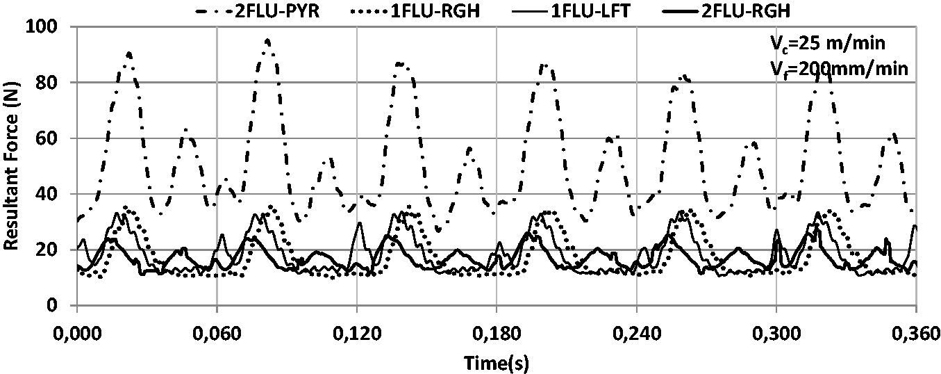
All other tools generated the quite consistent force results within the range of 20–40 N. This result suggests that, except for the pyramid tooth tool, all other tools can be used for cotton-FRP milling for selected parameters.
Burr formation
For the sake of detailed analysis of the burr formation on cotton-FRP milling for given parameters, one typical machined groove and used terminology is shown in Figure 6. The entrance and the top sides of the slot have the most intense burr contained regions in cotton-FRP milling. Those regions had quite different size and amount of the slot burrs which are the roll-over burr, entrance burr, and Poisson burr [17]. The entrance side of the tool was cited as the “down-milling side” and the exit side of the tool was cited as the “up-milling side.” During all cutting tests, less “entrance side and bottom” burr were observed in the up-milling side. According to the thorough analysis of burr formation on cotton-FRP milling, the Poisson burr and roll-over burr at the down-milling side were more intense than that of up-milling side.
Top view of the machined cotton-FRP groove and types of burrs (with 1FLU-RGH tool and Vc: 150 m/min, f: 200 mm/min).
Effect of cutting parameters and tool geometry on the burr formation of cotton-FRP.
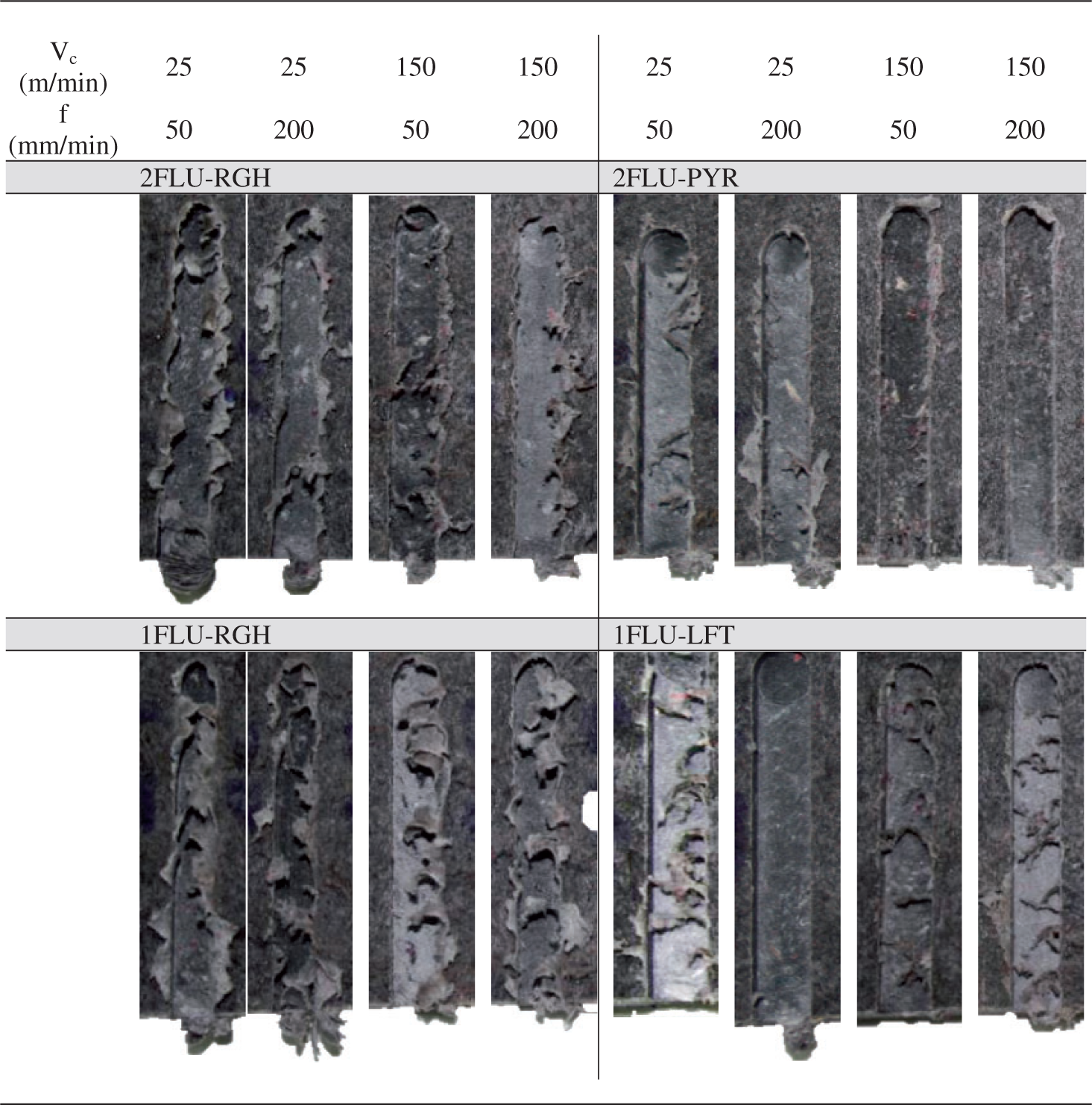

The amount of burr formed by pyramid tool, 2FLU-PYR, was less than the burr formed by other tools. Because of the adhered chips, the tool teeth could not make a clear cut. It causes ripped off the matrix material and ends up with ruined machined surface of cotton-FRP.
Heavy burr formation was observed at both sides and at the entrance of the groove during machining with both right helix tools. However, left helix tool, 1FLU-LFT, generates better burr formation among four different tool geometries. Besides, under the low cutting speed, 25 m/min, and high feed rate, 200 mm/min, conditions, the cleanest cut was accomplished while using one flute right helix tool. It was noticed that left helix tool pushing down the material during the cutting process caused less burr formation than the right helix tool. Conversely, the right helix tool pulled the chips up and bended without proper cutting action that resulted in the heavily burr formation compared to the left helix tool.
Chip morphology
The chips at the tool selection phase tests.


The chips morphology of right and left helix tool used tests were much the same. General form of chips for both types of tool is a fan shape chip. Fan shape chip begins with a spiral form but does not curl sufficiently due to the cotton fibers in it, and thus produces fracture prior to a complete revolution. The only difference was the chip curl directions. It was found out that the chip curl direction for right helix tools was clockwise and left helix tool was counterclockwise as expected. Both one flute right and left helix tools at low cutting speed and high feed rate condition created almost ideal chip form which is short ribbon chip form. The short ribbon shape of chip represents the fine cutting condition.
Cutting parameter selection phase
Tool selection phase test results suggested that one flute left helix tool (1FLU-LFT) was the most appropriate cutting tool for cotton-FRP machining in terms of chip morphology, burr formation, and cutting forces. On the other hand, the most applicable cutting parameters were selected as 25 m/min for cutting speed and 200 mm/min for feed rate within the utilized parameters. In fact although it was not the lowest cutting force achieved parameters, it was opted because it was four times more productive and the value difference of cutting force was 20 N which is not significant for WC tool.
Cutting parameters for cutting parameter selection phase.
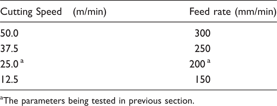
aThe parameters being tested in previous section.
Force results
Measured and calculated maximum resultant forces for one flute left helix tool for all cutting parameters are shown in Figure 7. Overall evaluation of the cutting force data shows that the effect of cutting speed on cutting force is more effective than the feed rate for selected range of parameters. The first two lowest cutting speed data, 12.5 and 25 m/min, show gradual increase with increasing feed rate and reach the highest value at 300 mm/min feed rate. There is almost no thermal softening effect observed for 12.5 m/min cutting speed test and highest force values were recorded as 90 N, at 300 mm/min feed rate.
Maximum resultant cutting forces for all cutting parameters in cotton-FRP milling.
The lowest cutting force values within the range of 25–35 N were obtained at both higher cutting speeds for almost all feed rate values. Again, the material softening effect with increasing cutting speed plays a crucial role due to the low thermal conductivity of the cotton-FRP material. The almost insignificant cutting force increase was also recorded due to the increasing chip load with increasing feed at higher cutting speeds except at 12.5 m/min cutting speed.
Burr formation for second stage cutting test
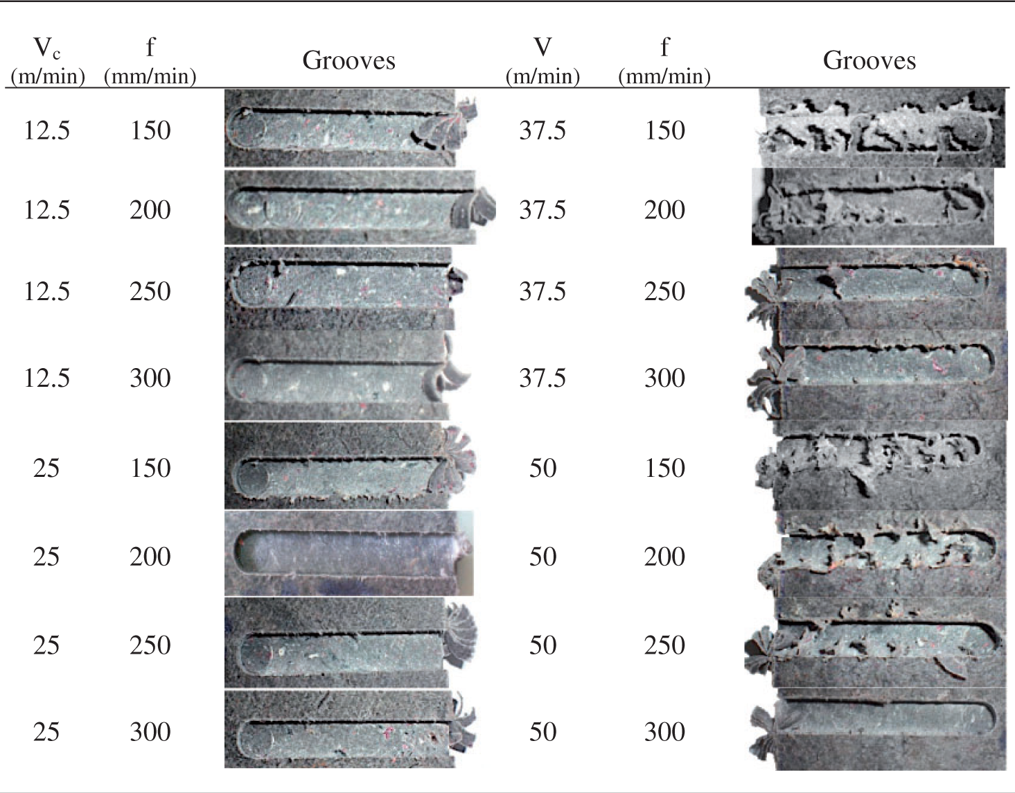
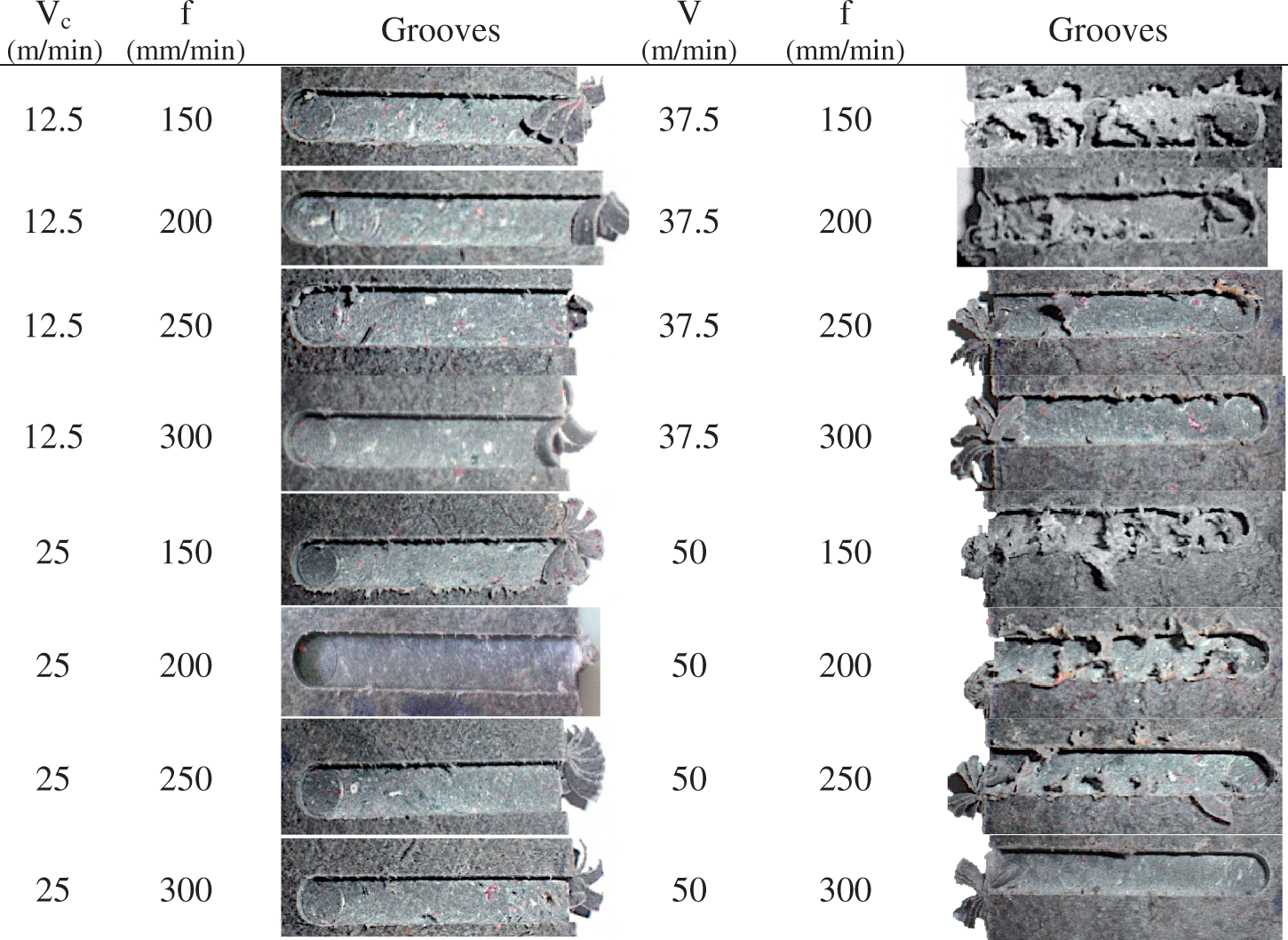
In order to compare the burr formation of the each blind slot more comprehensible, a qualitative scoring procedure was designed to determine the intensity of the each burr forms at the top side and the entrance side of the slots. The score range was from 1 to 5. According to the burr score procedure, minimum burr formation was assigned as the maximum score which was 5.
The optical micrographs of machines grooves and burr formations in cotton-FRP milling.
Burr scores for cutting parameter couples. The highest accumulative scores are indicated by boldface type.

The highest cumulative burr scores were obtained at the both lower cutting speed, 12.5 and 25 m/min conditions. As for increasing feed rate in the course of the constant cutting speed, the less amount of top side burr formation, Poisson burr, was examined in all conditions. The least top side burr formation was obtained at low cutting speed tests.
The higher cutting speeds and lower feed rate condition caused significant thermal softening and instead of expected clear layered roll-over burr, local melting caused entangled entrance burr forms. Results showed that the roll-over burr formation was inevitable at entrance side and it forms at any condition. Even so, selecting higher feed rate helped to get rid of burr entanglement and eases of successive deburring process.
The tool marks on the bottom side of the machined surface were also evaluated as a surface roughness, but it was not taken into consideration in burr formation score procedure. The tool marks at low cutting speed were more distinctive than that of high cutting speeds. When the cutting speed was increased the surface quality becomes better, but the amount of burr formation becomes heavier inversely.
Chip morphology for cutting parameter selection tests
The optical micrographs of chips were formed by one fluted left helix cutting tool.
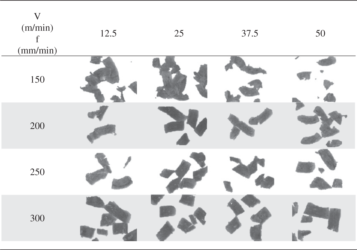

The SEM picture of the typical cotton-FRP chip obtained at 25 m/min cutting speed and 250 mm/min feed rate is given in Figure 8. The machined chip has a linty look due to the small and even size cotton fibers on chip. Yet, the chip had distinctively sharp edges and forms which are the signs of clear cut. The failure surface of cotton fibers (insets A and B in Figure 8) is the indication of the clear cut on cotton fibers without cracking, plastic deformation, or pull-out failures. Plastic deformation and pull-out failures would have caused uneven fiber diameter and gap formation in matrix–fiber interface, respectively. Having no pull-out failure also confirms that FRP has an acceptable matrix–cotton fiber interface bonding strength despite the absence of bonding agent. The ploughing lines were indicated with arrows in the LDPE matrix zone, which suggests the plastic deformation due to the easy yielding of matrix material.
SEM micrographs of cotton-FRP chip at 25 m/min cutting speed and 250 mm/min feed rate. (a) General form of linty look chip at low mag. (X36). (b) Deformation patterns of the composite structure in high mag. (X2090).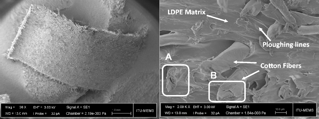
This SEM figure (Figure 8) and earlier optical image (Table 9) of chip forms assures that, when the correct cutting parameters and tool is selected, successful machining can be accomplished in cotton-FRP machining.
Overall evaluation of cotton-FRP machining
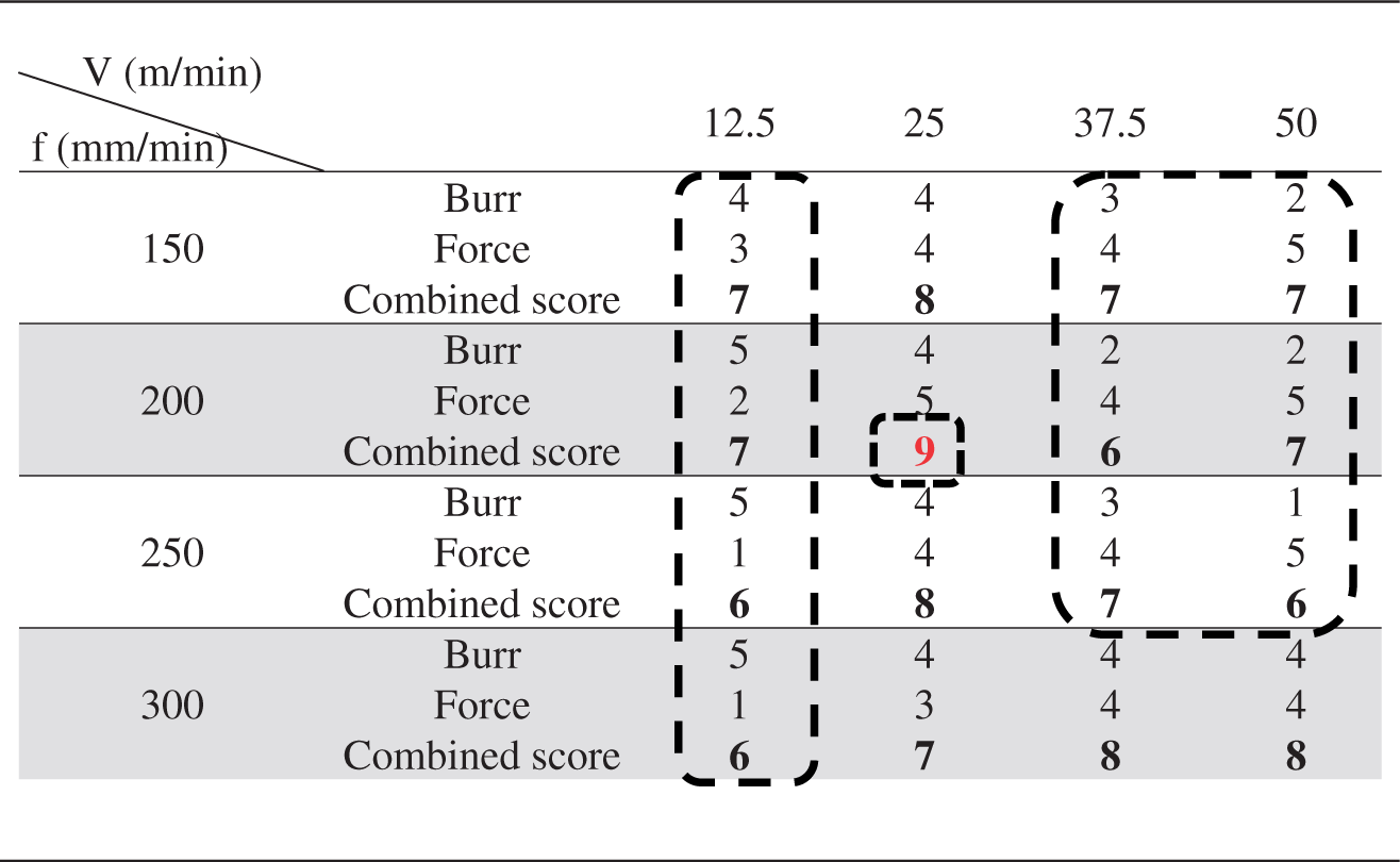
The corresponding scores for force analysis and burr formation.

The combined scores based on force and burr formation analysis for cotton-FRP machinability. Dashed regions show lower machinability parameters region.

A benchmark with pure LDPE
In this section, the cutting force values of cotton-FRP and pure LDPE which has the matrix material of cotton-FRP were compared for benchmarking purpose. The selected parameters and cutting force results are given in Figure 9. Except for the 25 m/min cutting speed and 250 mm/min feed rate parameters force data, higher cutting speed test force values were quite similar for both materials. The benchmarking tests suggest that the machinability of cotton-FRP is not quite different than that of LDPE based on cutting forces.
Cutting forces of cotton-FRP and PE at selected cutting parameters with one flute left helix tool.
Conclusion
This work attempts to evaluate machinability of the novel composite material, cotton-FRP, for the very first time during milling process by means of detailed tool selection, cutting force measurement, chip morphology, and burr formation analysis. The paper deals at first selection of tool geometry and the results of cutting tests were suggested that the one flute left helix WC tool was the most suitable geometry for milling process. This result was supported by cutting force, burr formation, and chip morphology analysis.
The burr formation analysis figures out all three types of typical blind channel slot milling burrs—roll-over, Poisson, and entrance—formed during machining of cotton-FRP. One of the important finding of the burr formation analysis was the importance of cutting speed in burr formation. The results showed that cutting speed was the dominant parameter than the feed rate in terms of burr formation. Higher cutting speed caused higher burr formation.
General form of the milling chips of the cotton-FRP was the short ribbon shape chips with linty look due to the embedded cotton fibers in LDPE matrix. Overall evaluation of milling test results which were the combination of cutting force and burr formation analysis suggested that the lowest cutting force and the cleanest burr formation can be obtained at 25 mm/min cutting speed and 200 mm/min feed rate.
Finally, the benchmarking tests were proposed that the machinability of cotton-FRP is not quite different than that of LDPE based on cutting forces.
Overall results confirm that cotton-FRP can be used for garden furniture, garbage bins, park playground equipment, and the interior automotive trimming parts type of applications.
Footnotes
Declaration of Conflicting Interests
The author(s) declared no potential conflicts of interest with respect to the research, authorship, and/or publication of this article.