
Abstract
The main disadvantage of the current electrospinning and related processes for producing nanofibers is low throughput rate, which is a challenge for quite some time. Traditional approach of studying the influence of one factor at time on nanofiber diameter does not give a complete picture of the process, where many interacting process parameters are being neglected. This paper reports a melt spinning process to increase the production rate of nanofiber materials. An additional attachment was fixed below the filament extruder of a melt spinning line. This attachment with controlled heated airflow arrangement stretches the filament coming out of the extruder by the process of sequential drawing which result in the formation of nanofiber materials. A die with segmented cross-section was used during melt extrusion process. A Box and Behnken factorial design of experiment was conducted to study the influence of multiple parameters on fiber/filament diameters. These parameters were distance of the first drawing zone from the die, airflow, and air temperature. The selected parameters were varied at three levels, −1, 0, and +1, respectively. The current setup produces fibers with diameter ranging from 820 to 1145 nm, smallest diameter was 820 nm. Among the selected parameters, the interaction effect of the air temperature and distance of the first drawing zone from the die was a dominant factor on the extrusion of nanofibers. These results show that in a multivariable process, interaction effect of the parameters played a major role in determining fiber diameter and it cannot be neglected.
Introduction
A fiber having diameter less than 1 µm (1000 nm) is known as nanofiber [1]. Current methods of producing nanofibers are electrospinning, bubble spinning, force spinning, melt blowing, and melt spinning [2–12]. Among these methods, electrospinning is very successful in producing fibers with diameter in the range of 50–1000 nm. The smaller the fiber diameter, the greater its value in various advanced applications like tissue engineering, scaffolds, filtration, etc. [2, 3]. The main disadvantage of the electrospinning process is very low production rate which is in the range of 0.5 mg–1 g/h depending on the polymer concentration [3]. By contrast commercial fiber spinning operates at a very high rate, in the magnitude of several hundreds, around 800 kg/h [3, 4]. In one of the study, author highlighted the need for increasing the production rate of nanofiber materials for commercial acceptance [3]. One possible way to increase the productivity of electrospinning is by using multiple nozzles or spikes [4, 6, 8]. Some of the disadvantages of this process are neighboring electric fields interfere with each other which affects the nanofiber formations, controlling the process parameters were difficult, and it was not practically feasible on a commercial scale [2]. In addition, most of the time, polymer needs to be dissolved in solvents for electrospinning to be carried out. The polymer concentration ranges from 2 to 20% in a solvent and such a low polymer mass will always result in low throughput [2–4]. Furthermore, electrospinning process has other disadvantages like release of toxic fumes during nanofiber formation, resulting in hazardous working conditions and at times, certain solvents need to be recovered, which increases the energy consumption of the process [9–12]. The high voltage source required for electrospinning was another potential danger.
Melt electrospinning, melt blowing, and melt spinning are other possible methods to increase the throughput of nanofibers [5, 7, 9–12]. Particularly in the case of melt blowing and melt spinning, the die design needs to be changed for high throughput. The die orifice holes were in the order of 0.025–0.12 mm, in order to obtain fiber diameter in nano dimension. It was an expensive process to manufacture such a smaller die holes. Furthermore, a high pressure was required to force out the polymer through the die orifices. In this situation, the chances of die cracking are very high because of the small size of the die orifices. Some other means have been developed to avoid die cracking, for example, by placing a series of dies or thin plates by stacking over one another. But this leads to other problems such as higher pressure requirement for forcing the polymer through the die orifices and blockage of the die orifices by the polymer because of the smaller size. A patented melt spinning method was described for high throughput of nanofibers [12]. This method was based on the principle of using a high speed rotating disc to split the molten polymers into nanofibers by centrifugal force. This method might provide high throughput, but obtaining a uniform nanofiber would be problematic as there were chances of bulking of the nanofibers, when they were subjected to such a high speed. Moreover, the process would also affect the fiber orientation and other properties.
Nayak et al. [5] discussed a method for fabricating nanofibers by melt blowing process with the injection of fluid such as air and water to the melt blowing equipment. The lowest average fiber diameters obtained in this process were 755 and 438 nm by the use of air and water, respectively. Some of the fiber diameters in micron level were also obtained in this process. Some published literature suggests that melt blowing can be used to synthesize nanofibers, with minimum average fiber diameter ranging between 1 and 2 µm [13, 14]. In another published work, authors reported average fiber diameter of 500 nm by melt blowing process [15]. Although a limited research work was published on increasing the productivity of nanofibrous materials by various methods [5, 13–15], there is a lack of research work in open literature on optimization of process parameters by considering multiple parameters at a time. Most published research literature focuses on studying the influence of one parameter on fiber diameter. There were some published literatures in the electrospinning side, covering the optimization of parameters by considering multiple parameters at a time [16, 17]. In a multiple variable process like melt spinning, considering multiple variables will show the influence of individual parameters and also their interaction effects, which cannot be predicted in a single factor study. In this regard, response surface methodology using Box and Behnken factorial design is a very useful tool in studying the influence of multiple variables simultaneously [18, 19].
The objective of this work is to increase the production rate of nanofiber polymeric materials with a modified process during melt spinning. In this proposed work, there is an additional attachment fixed below the filament extruder for enhancing the productivity of nanofiber materials. Another objective of this work is to study the influence of multiple parameters on fiber diameters. The parameters studied were distance of the first drawing zone from the die, airflow rate, and air temperature. The selected parameters were varied at three levels, namely −1, 0, and +1, respectively. The response surface methodology was applied to predict fiber diameters from the processing parameters.
Experimental
Polypropylene pellets with melt mass flow rate of 50 g/10 min were used for melt spinning, followed by sequential drawing or two step drawing process. Pellets were obtained from Sasol Polymers, South Africa and used as it is without any modification. A pilot scale filament extrusion line (Fiber Extrusion Technology, Leeds, UK, Model C-0086) was used for melt extrusion. A schematic of the setup is shown in Figure 1. A segmented-pie die with 36 holes was used for the melt spinning. The diameter of each hole in the die was 0.5 mm. The following parameters were used in melt extrusion process: rotational speed of metering pump (r/min), 3; prepump pressure (bar), 60; extruder barrel temperature (℃), 180, 180, 200, 200; die head temperature (℃), 220; hood temperature (℃), 40. A stainless steel rectangular box (20 mm × 70 mm) was fixed to the melt spinning line with the help of screws. In Figure 1, D stands for the distance of the first drawing zone from the die.
A schematic of the experimental setup.
Levels of variables for design of experiment.

Coded levels and actual values of variables for different experimental combinations along with average fiber diameter.
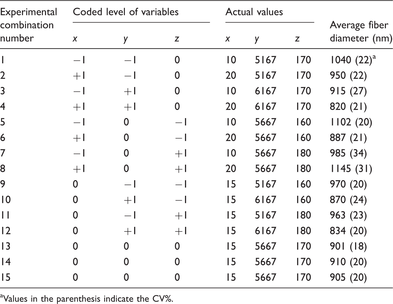
Values in the parenthesis indicate the CV%.
The distance below 10 cm was not possible because of the issues relating to fixing of the rectangular box as enough space was not available. Similarly, distance above 20 cm was not possible due to inadequate stretching intensity of the airflow. Six heat guns (Steinel HG 2310 LCD, Steinel UK) with variable temperature and airflow settings were used at the first and second drawing zones as well as in the additional heated air supply areas. Four heat guns were used for stretching of the fibers/filaments, two on both sides of the rectangular box (Figure 1). These heat guns were the sources of heated air inlets in the first and second drawing zones. Furthermore, two additional heat guns were used as the source of additional heated air supply at the exit of the die. The purpose of this additional heated air supply was to maintain the molten stage of the polymer melt while emerging from the die. Since the rectangular box was fitted at a distance ranging between 10 and 20 cm distances from the die, there were chances of filament solidifying at the room temperature. Same levels of air temperature (160, 170, and 180℃) were maintained at the inlet of additional heated air supply and at both drawing zones while performing the experiment. Airflow was measured by an airflow meter (Kestrel Meter 4200, Birmingham, MI, USA). Cooling zone temperature was maintained at 20℃. A fixed collector was used to collect the nanofiber polymeric materials. Nanofibers were bonded together with the help of heated air temperature maintained at 150℃. The structural morphology and diameter of the fibers were determined by scanning electron microscope (SEM) FEI Quanta 200 and 50 readings were taken for measuring the fiber diameter and average value was reported.
Results and discussion
Process for formation of nanofiber polymeric materials
The process involves controlled heated airflow to stretch the filament emerging from the extruder by sequential drawing in two steps, which ultimately results in the formation of nanofiber materials. After stretching the filament in the first drawing zone, further stretching in the second drawing zone was achieved by the heated airflow. Same air temperature was maintained in both drawing zones. For example, while operating at 160℃, both stretching zones were maintained at 160℃. The advantage of sequential drawing was that high stretching can be imparted in a two-step process, thereby, allowing greater control over fiber diameter. The turbulence created by the heated airflow was avoided and possible buckling of the fibers/filaments was also eliminated. Filaments were also subjected to additional heated air supply, in order to maintain the molten state of the polymer melt while emerging from the die, so that quick solidification of the filaments can be avoided. For a continuous stretching of the filament, it was necessary to keep them in a molten state.
After drawing through the extruder, the filaments were passed through a cooling zone, placed at a distance of 10 cm below the exit of the rectangular box. This process was followed by depositing the filament over a fixed collector and through heated air was used to bond the filaments in the form of nonwovens over the collector. The heating and cooling were critical in the process. The heated airflow not only assisted in stretching the filaments, but also provided improved molecular orientation within the filaments, which resulted in the adequate strength of the nanofiber materials. The cooled air was helpful in stabilizing the molecular structure of the filaments/fibers in the polymeric materials. The formation of fibers with diameters in nanometer and micrometer ranges can be seen in Figure 2(a) to (d). Also, in some cases the formation of fibers with diameter in the micrometer range can be seen in Figure 2(c). The reason for formation of fibers with diameter in the nanometer and micrometer range was related to the selection of the process parameters (distance of the first drawing zone from the die, airflow, and air temperature). The production rate of a single head was about 3 kg/h, which was much higher than the multiple nozzle electrospinning [4, 6, 8] and similar type of arrangements like disc/force spinning [12]. The reason for high productivity was due to the use of high speed filament extruder equipped with a separate attachment placed outside without altering the original configuration of the machine. This method does not require any solvents or high voltage power source [2, 3] and provides a cost-effective way to increase the productivity of nanofiber materials.
(a) Typical SEM image of the sample from the experimental combination number of 3 (10 cm distance, 6167 cm3/s airflow rate, and 170℃ air temperature). (b) Typical SEM image of the sample from the experimental combination number of 4 (20 cm distance, 6167 cm3/s airflow rate, and 170℃ air temperature). (c) Typical SEM image of the sample from the experimental combination number of 8 (20 cm distance, 5667 cm3/s airflow rate, and 180℃ air temperature). (d) Typical SEM image of the sample from the experimental combination number of 9 (15 cm distance, 5167 cm3/s airflow rate, and 160℃ air temperature).
Optimization
Analysis of variance for three variables, significance probability (P-value), and correlation coefficient.

Equation (1) is a relationship between the dependent variable (fiber diameter) and independent variable (process parameters). This equation was established after a series of regression calculation done at 95% confidence interval.
The response surface equation for an average fiber diameter was given by


The response surfaces of fiber diameter as a function of selected processing parameters are discussed in the next section. Three different cases have been considered as per the statistical significance and dominance of the selected parameters in obtaining uniform fiber diameters. Figure 2 shows some randomly selected SEM images from 15 sets of experiments showing the morphology of the fibers.
Function of air temperature and distance of the first drawing zone from the die at constant airflow rate
The interaction between air temperature and distance of the first drawing zone from the die on fiber diameters at an airflow rate of 6167 cm3/s is shown in Figure 3(a). The values of fiber diameter at −1, 0, and +1 levels of air temperature were 1134, 848, and 794 nm, respectively. With the increase in air temperature from −1 to 0 level (1134 and 848 nm) and from 0 to +1 level (848 and 794 nm), respectively, 25 and 6% decrease in fiber diameter was observed. Overall, with the increase in air temperature from −1 to +1 level (1134 and 794 nm), about 30% decrease in fiber diameter was observed. This decrease in fiber diameter can be due to the molten state of the polypropylene polymer at higher air temperature which facilitates easy drawing. With the increase in air temperature, the entanglements among the polymer chains were weak and it was easy to stretch them further, resulting in thinner diameter fibers/filaments. The air temperatures were set according to the melting point or glass transition temperatures of the polymer. The air temperature setting process was similar to the melt blowing process, where a precise setting of the air temperature was required to obtain thinner fibers [20].
(a) Contour plots of the interaction effects of the air temperature and distance of the first drawing zone from the die on fiber diameter at constant airflow (6167 cm3/s). (b) Contour plots of the effects of the airflow and air temperature on fiber diameter at constant distance of the first drawing zone from the die (10 cm). (c) Contour plots of the effects of the distance of the first drawing zone from the die and airflow on fiber diameter at constant air temperature (160℃).
Fiber diameters at 10, 15, and 20 cm (−1, 0, and +1 levels) distance of the first drawing zone from the die were 1134, 900, and 854 nm, respectively. With the increase in distance of the first drawing zone from the die from −1 to 0 level (1134 and 900 nm) and from 0 to +1 level (900 and 854 nm), respectively, 21 and 5% decrease in fiber diameter was observed. Overall, with the increase in distance of the first drawing zone from the die from −1 to +1 level (1134 and 854 nm), about 25% decrease in fiber diameter was observed, which resulted in yielding finer fibers. Irrespective of increase in distance, the molten state of the polymer melt was maintained by the air temperature, which contributed to the formation of finer fibers. These findings were opposite to the effect of increasing the die to collector distance during melt blowing process [21, 22]. The reason for such a discrepancy was attributed to the constant air temperatures in the case of this new process which allows the stretching to continue. Maintaining such a condition during the conventional melt blowing process with the increasing distance between die to collector was not possible, therefore higher fiber diameters were obtained.
The combined influence of air temperature and distance of the first drawing zone from the die to the fiber diameter shows that +1 level of air temperature (180℃), +1 level of distance of the first drawing zone from the die (20 cm), and +1 level of airflow rate (6167 cm3/s) resulted in the smallest fiber diameters in the range of 820–794 nm. This is the optimized region for the above selected parameters. An experimental verification showed that smallest fiber diameter obtained by using above combination was 805 nm.
Function of airflow and air temperature at constant distance of the first drawing zone from the die
The interaction effect of airflow and air temperature on fiber diameters at a 10 cm distance of the first drawing zone from die is shown in Figure 3(b). The values of fiber diameter at −1, 0, and +1 levels of airflow were 1164, 1164, and 1059 nm, respectively. Overall, with the increase in air temperature from −1 to +1 level (1164 and 1059 nm), 9% decrease in fiber diameter was achieved, although fiber diameters were still in the micron level. This decrease in fiber diameter can be attributed to increasing intensity of stretching of the filaments, thereby making them thinner [23].
Fiber diameters at −1, 0, and +1 levels of air temperature were 1164, 1024, and 980 nm, respectively. Overall, with the increase in levels of air temperature from −1 to +1 level (1164 and 980 nm), about 16% decrease in fiber diameter was achieved as discussed in the previous section.
Function of distance of the first drawing zone from the die and airflow at constant air temperature
The interaction effect of distance of the first drawing zone from the die and airflow at constant air temperature of 160℃ is shown in Figure 3(c). The values of fiber diameter at −1, 0, and +1 levels of airflow were 1200, 960, and 920 nm, respectively. Overall, with the increase in distance of the first drawing zone from the die from −1 to +1 level (1200 and 920 nm), the fiber diameter decreased by 23%. This may be due to the molten state of the polymer discussed earlier, which aids in effective stretching, thus making the fibers/filaments thinner.
Similarly, fiber diameters at −1, 0, and +1 levels of airflow were 1200, 1160, and 1060 nm, respectively. Overall, with the increase in airflow from −1 to +1 level (1200 and 1060 nm), about 12% decrease in fiber diameter was observed.
Limitation
The main limitation of the current setup is that the sequential stretching or air drawing is not enough to reduce the fiber diameters below 500 nm. In order to achieve it, another different setup is needed, where there will be greater control over airflow, along with increasing the maximum airflow thrice of its current value. Also, the length of the sequential drawing zone (40 cm) is not enough to stretch the filaments further. Furthermore, two additional air inlets, one each at the 1st drawing zone and 2nd drawing zone can be used to further stretch the filaments and make it finer to get the fiber diameters below 500 nm.
Conclusions
Sequential drawing process was used to increase the production rate of nanofiber polymeric materials. A factorial design of experiment was conducted to study the simultaneous influence of multiple parameters on fiber diameter. At a 20 cm distance of the first drawing zone from the die, 6167 cm3/s of airflow, and 180℃ of air temperature provided the smallest nanofibers with diameters ranging from 820 to 794 nm. Among the selected parameters, interaction effect of the air temperature and distance of the first drawing zone from the die was the most dominant in influencing the fiber diameter which was followed by the individual factors, namely distance of the first drawing zone from the die and airflow parameters, respectively. In a multivariable process, interaction effect of the process parameters played a major role in determining fiber diameter and it should be considered. This method does not use any solvents or high voltage source and the production rate was about 3 kg/h.
Footnotes
Declaration of Conflicting Interests
The author(s) declared no potential conflicts of interest with respect to the research, authorship, and/or publication of this article.
Funding
The author(s) disclosed receipt of the following financial support for the research, authorship, and/or publication of this article: The authors gratefully acknowledged funding from the CSIR parliamentary grant project.