
Abstract
In this paper, glass fiber felts are fabricated by centrifugal-spinneret-blow process. Swing cylinder is designed to obtain a micro-layer structure, and the phase difference of two swing cylinders is π/2 + 2kπ. Tensile strength, flexural rigidity, and thermal conductivity of various glass fiber felts are investigated. The experimental results indicate that the tensile strength of micro-layer glass fiber felts and random glass fiber felts is 0.015 MPa and 0.013 MPa, respectively. In addition, the tensile strength of glass fiber felts is also improved with the increase of the density and the resin content of glass fiber felts. The micro-layer structure decreases the flexural rigidity of glass fiber felts, and the flexural rigidity of glass fiber felts with micro-layer and random structures is 43.4 g.cm and 101.3 g.cm, respectively. The mean thermal conductivity of glass fiber felts with micro-layer and random structures is 31.57 mW/m·k and 35.69 mW/m·k, respectively.
Introduction
Glass fiber felt is a porous material, well known for its thermal and acoustic insulation properties, which are widely used in building constructions, aeronautical application, and transportation [1,2]. For some particular applications, physical properties are also required such as tensile strength, flexural rigidity, and thermal conductivity.
Champagne and Angers [3] presented that glass fiber felt was mainly produced by centrifugal-spinneret-blow (CSB) and made from a set of disordered fibers which was consolidated by local thermal fusion or chemical binders. The characters of raw glass fiber, such as fiber diameter, fiber length and distribution, closely depended on the processing technique. Novitskii and Efremov [4] investigated the fiber blowing process in the production of mineral wool; the results indicated that fiber formation and the length of the secondary fiber depended on the viscosity of a melt and gas jet velocity, respectively. Bajcar et al. [5] focused on the study of the mechanisms of mineral wool primary layer formation and analyzed the problems of non-uniform of fibers distribution. Blagojevic et al. [6] explored a novel method of measurement to control the primary layer quality in mineral wool production processes and all the key parameters in the model could be measured in a real production process. High porosity and excellent deformation ability of fibrous materials led to superiority in terms of sound insulation, thermal insulation, and tensile strength. The physical and mechanical properties of fibrous materials were complex, and more experiments and numerical simulations were developed to gain a better understanding of the mechanical performance. Steponaitis et al. [7] explored the structure and deformation mechanisms of mineral wool slabs under compression and found that the deformation mechanism of mineral wool products depended on the material thickness. Gnip et al. [8] analyzed the strength and deformability of mineral wool slabs under short-term compression and explored the relationships between the tension and shear characteristics. Achchaq et al. [9] mainly explored the hydric, morphological and thermo-physical characterization of glass wools: from macroscopic to microscopic approach. Rizvi et al. [10] explored the influence of micro-structure on the mechanical behavior of fibrous material and found that the randomness of fiber orientation made the fibrous structure more flexible at the cost of lower strength. Borodulina et al. [11] investigated the relation between micro-mechanical processes and the stress–strain curve of a dry fiber network during tensile loading, and the results showed that failed bonds were located in the places with high local strain. Faessel et al. [12] established a 3D model of random fibrous networks, which turned out that the length and the horizontal orientation of the fibers seemed to have a very low influence on the thermal conductivity compared with other parameters such as density, vertical orientation, and tortuosity of the fibers.
In the traditional CSB, glass fibers floated freely and the distribution of fibers was random. Till date, there are few reports published on micro-layer glass fiber felts by the CSB process. In this article, swing cylinders were used to obtain the micro-layer structure. The method of superposition and the forming theory of micro-layer were discussed. The physical properties of glass fiber felts with different processes were also contrasted.
Experiment
The preparation of glass fiber felts
In this paper, glass fiber felts were produced by CSB process. Figure 1 shows the schematic diagram of CSB process. Raw materials such as recycled glass, quartz sand, albite, calcined soda, calcite, and borax pentahydrate are first transported to the independent vertical silos. They are accurately weighed and uniformly mixed at a specific ratio. Then the raw material is melt into glass liquid by electric melting furnace at the temperature of 1300℃. The glass liquid is clarified and homogenized in the fore hearth by gradient temperature control method. Vitreous fluid at the temperature of 1100℃ flows out from the leak board and forms a vitreous fluid stream; then the vitreous fluid stream falls vertically into a centrifuge pan which rotates at the speed of 3500 r/min. The primary glass fibers are formed through pores on the pan’s surrounding wall by making use of the centrifugal force. These high-temperature primary fibers are immediately affected by air current jetted from ring-form combustion nozzles arranged concentrically with the centrifugal pan and the hot airflow from the nozzles is 1200℃. Then the primary fibers further split and stretch into secondary fibers, namely glass fiber [13–15]. Phenolic resin adhesive is sprayed before the glass fibers reach the perforated mesh. Finally, glass fibers with phenolic resin adhesive are sent into a curing furnace where glass fiber felts are formed.
Schematic diagram of centrifugal-spinneret-blow process.
Measurements
Samples for all the measurements were cut from different places covering the whole felt, and the direction was perpendicular to the large surface which was parallel to the conveyor belt used in the manufacture. The sizes of different samples were cut according to the testing standard.
Tensile strength and flexural rigidity
Tensile strength was measured on a universal material testing machine (HOUNSFIELD H10KS) by standard FED-STD-191, Method 5100. During tensile test, the stretching speeds of the cross-head were all set to be 305 ± 13 mm/min. The size of sample is 152 mm × 76 mm. Each sample will be tested five times and averaged.
Flexural rigidity of glass fiber felt was determined by the ‘International Standard ISO 9073-7:1995 Textile test methods for non-woven Part 7: determination of the bending length’. Bending length is a measure of the interaction between fabric weight and fabric stiffness in which the fabric bends under its own weight. In this testing, the size of sample is 200 mm × 76 mm.
Thermal conductivity
Thermal conductivity of glass fiber felts was determined by heat flow meter thermal conductivity instrumentation (Netzsch HFM 436). The size of sample is 300 mm × 300 mm.
Structural characterization
The cross-sectional structures and internal morphology of glass fiber felts were investigated by the optical microscope (BD-200) and scanning electron microscopy (SEM, JEOL JSM-6360), respectively. The thicknesses of glass fiber felts were measured according to BMS8-48, section 8.3.
Results and discussion
Forming theory and structural characterization of glass fiber felts
Analysis of trajectory of glass fibers
Swing cylinders are designed to obtain the micro-layer structure. The falling trajectory of glass fibers is similar to a simple pendulum movement when glass fibers pass through a swinging cylinder. The swing cylinder is assumed as an hourglass, with a conveyor belt under the swing cylinder, and the trajectory of glass fibers on the conveyor belt is a sine or cosine curve. A three-dimensional coordinate system is built to accurately analyze the forming theory of micro-layer glass fiber felts. The Z axis is perpendicular to the conveyor belt and the X-axis is parallel to the direction of the moving conveyor belt. The Y-axis is perpendicular to the plane X–Z, and the plane of swing cylinder movement is Y–Z. The schematic diagram of the trajectory is shown in Figure 2(a). For one centrifuge pan and one swing cylinder, the trajectory of glass fibers is shown in Figure 2(b).
Schematic diagram of the trajectory of glass fibers: (a) the trajectory between swing cylinder and glass fibers and (b) the trajectory of glass fibers.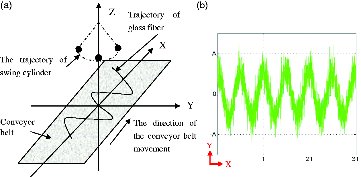
Theoretical analysis of structural formation
Yang et al. [16] explored the processing of swing cylinders and found that the best way of superimposition could be obtained when the phase difference of two swing cylinders was π/2 + 2kπ. For one swing cylinder, the trajectory of glass fibers is sine curve, and the way of fiber accumulation is shown in Figure 3. The speed of swing cylinder gradually decreased when the swing cylinder moved to the critical points (point 1 and point 2). The speed of swing cylinder reached at its minimum value, i.e. 0, at the critical points. The distance of per unit time decreased leading to the increase in the number of fiber accumulation. When the swing cylinder moved to the lowest point (point 3), the speed of swing cylinder arrived at the maximum value, the number of fibers was decreased on the conveyor belt. According to the way of fibers accumulation of one swing cylinder, glass fibers on the middle part of conveyor belt was less than that on the edging portion.
The accumulation of glass fibers: (a) glass fiber distributionand (b) the trajectory of glass fibers.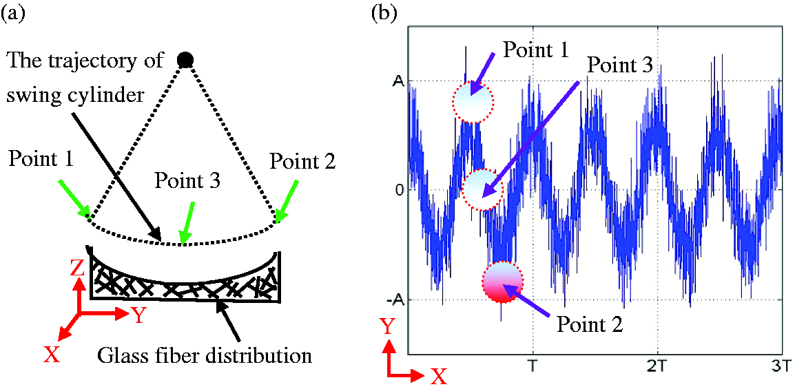
With the increase of the oscillation frequency of swing cylinder, the wavelength of the trajectory of glass fibers could be reduced. Glass fibers can be superimposed and form a micro-layer structure as shown in Figure 4(a). At the same time, when the number of swing cylinders was more than one, the superimposed glass fibers could help to obtain a micro-layer structure. Two swing cylinders were used to produce glass fiber felts, and the phase difference of two swing cylinders is π/2 + 2kπ as shown in Figure 4(b). The superimposed section of glass fibers was mainly limited to the middle part of conveyor belt; the uniform glass fiber felts with a micro-layer structure could be further obtained.
Superposition of glass fibers: (a) Superposition by one swing cylinder and (b) superposition by two swing cylinders.
Structural characterization of glass fiber felts
The character of fibers and microstructure of fibrous material can affect the physical properties. However, the arrangement of fibers in fibrous materials is very complicated. Generally, the actual geometry and orientation, pore size and structure are normally unknown characteristics. The internal and cross-sectional structures of glass fiber felts are shown in Figure 5. It indicated that glass fiber felts could obtain various cross-sectional structures by different processes. The cross section of glass fiber felts with no swing cylinder exhibited random distribution. Glass fiber felts obtained a micro-layer structure by adding the swing cylinders. It could be considered that most fibers were parallel to the surface; few fibers were orientated perpendicular to the surface in glass fiber felts. It was also found that the fibers in glass fiber felt were mainly placed in dense layers (most fibers) separated by loose layers (less fibers). There were alternative distribution between dense layers and loose layers in the thickness direction. The internal structure of all glass fiber felts was disordered.
Cross-sectional and internal structure of glass fiber felts: (a) with no swing cylinder and (b) with swing cylinders.
Tensile strength
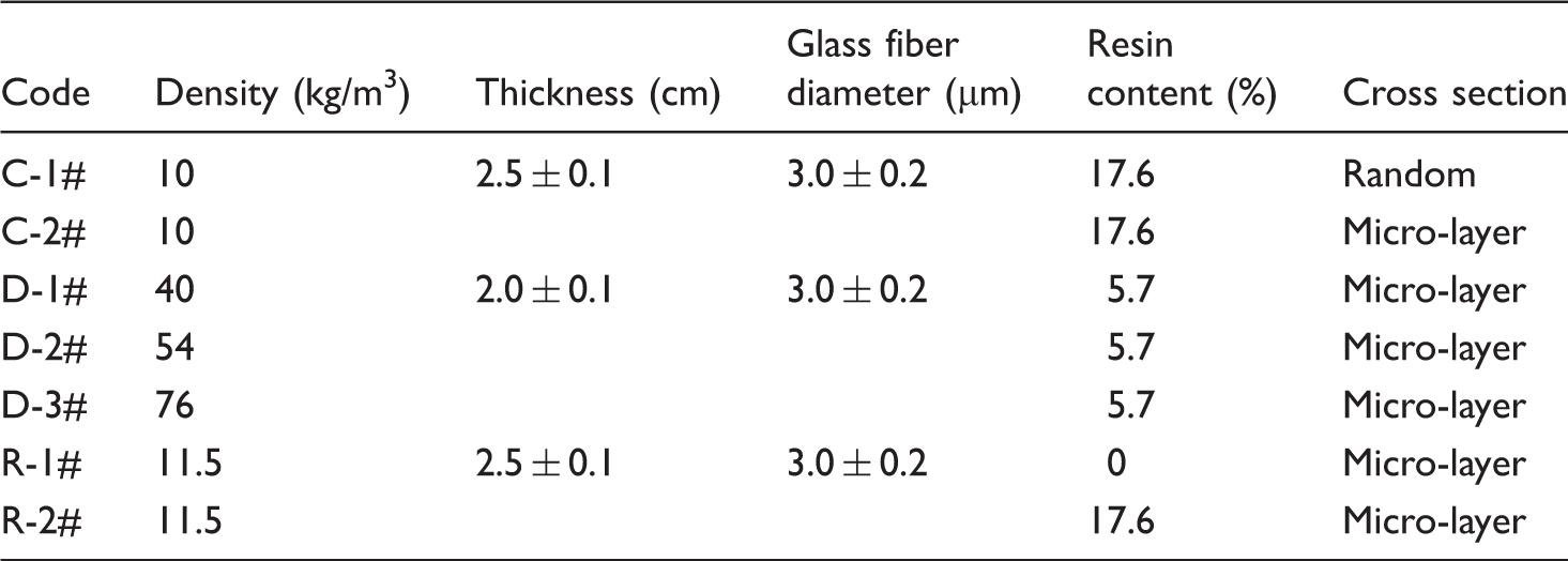
The parameters of glass fiber felts.
The tensile strength of glass fiber felts with random and micro-layer structure, i.e. sample C-1# and sample C-2#, is shown in Figure 6(a), suggesting that the tensile strength of C-1# and C-2# was 0.013 MPa and 0.015 MPa, respectively. It was obvious that the tensile strength of glass fiber felts with micro-layer structure was better than those with random structure. The tensile strength of glass fiber felts could be improved a little by the microstructure. For glass fiber felts with micro-layer structure, the axes of fibers were located on planes parallel to each other with random positions and orientations on these planes. In micro-layer structure, higher arrangement level of fibers led to the two-dimensional distribution, conversely to the random distribution such as three-dimensional distribution (in random structure). The mechanical strength of fibrous materials was associated with the mechanical strength of a part of the fibers, which resisted longitudinal stretching and thereby provided mechanical strength to the fibrous materials. Most fibers with two-dimensional distribution that spanned the entire glass fiber felt longitudinally could bear the tensile load leading to improve the tensile strength. However, fibers with three dimension provided very a little mechanical strength, as they were already broken when they had not reached the largest fiber tensile strength.
Tensile strength of glass fiber felts with different structural parameters: (a) effect of cross-sectional structures; (b) effect of densities; and (c) effect of resin contents.
Figure 6(b) shows the effect of different densities of glass fiber felts on tensile strength. The results showed a proportional relationship between density and tensile strength. An increase in density resulted in an increase in tensile strength of glass fiber felts. With the increase of density, it yielded more fiber within the unit area. Most fibers could bear the tensile load leading to the increase of tensile strength of glass fiber felts. The tensile strength of glass fiber felts with different resin contents is shown in Figure 6(c). When glass fiber felts were composed of resin and glass fibers, which had higher tensile strength compared with that with no resin. Cherkassky et al. [17] built a model of one-dimensional fibrous materials tensile strength based on the slippage effect and only frictional and traction forces determined the tensile strength in this kind of the model. Maybe this model suited for the glass fiber felts with no resin content (as shown in Figure 7(a)), because tensile strength of these samples were mainly based on both the tensile strength of fibers and the friction between the fibers. However, under the action of resin, part of fibers was guided into a small amount fiber bundle in glass fiber felts (as shown in Figure 7(b)). The bundle fiber played an importssant role in this improvement. It was equivalent to a small amount of strengthened fibers that enhanced the strength of glass fiber felt and improved the tensile strength. In this case, the tensile strength of glass fiber felts mainly depended on the mechanical properties of fibers and fiber bundles and crosslinking of resin.
The morphology of glass fiber felts: (a) with no resin content (0%) and (b) with resin content (17.6%).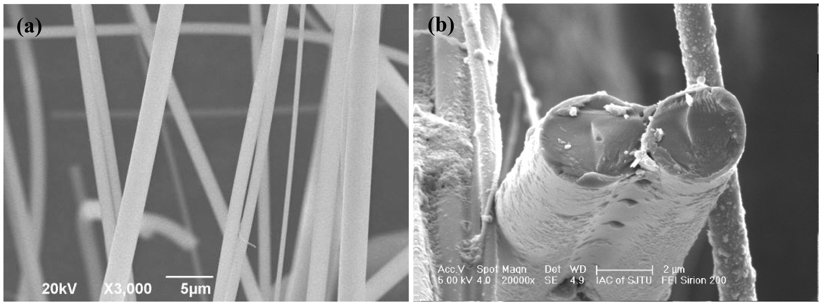
Flexural rigidity of glass fiber felts
Flexural rigidity of glass fiber felts with different cross-sectional structures.

Thermal conductivity
The thermal conductivity is regarded as the most important property of fibrous materials. Glass fiber felt consisted of solid phase and gas phase, and gas phase filled in the voids among solid phases. The thermal transport through a material according to the thermal gradient could be quantified by the material’s thermal conductivity λtot [W/(mK)]. Kwon et al. [21] stated that the total thermal conductivity λtot could be summarized as follow

Thermal conductivity of various glass fiber felts was measured, and the results are graphically illustrated in Figure 8. The mean thermal conductivity of glass fiber felts with micro-layer and random structures were 31.57 mW/m·k and 35.69 mW/m·k, respectively. The random characteristics of microscopic positions and connections of fibers made the thermal conductivity fluctuate around an average value for same macroscopic parameters. Generally speaking, the thermal properties of a fibrous material depend on the thermal properties of each phase (fiber and air), fiber volume fraction, and structure (fiber size, orientation and mass distribution) [22]. Fu and Lauke [23] found that the thermal conductivity of the composite decreased with mean fiber orientation angle with respect to the measured direction. Arambakam et al. [24] showed that heat conduction through the solid fibrous structure increased by the increasing of solid volume fraction, fiber diameter and fibers’ through-plane orientations. For glass fiber felts with micro-layer structure, most fibers arranged in the same plane. This structure helped to decrease the thermal conductivity of glass fiber felts. Zhu et al. [25] considered that numerous pore channels within fibrous porous materials consisted of parallel channels to the heat flow direction and perpendicular channels to the heat flow direction. The alternative distribution between dense layers and loose layers in the thickness direction resulted in discontinuous link of micro-structural pores. This absence of interconnected micro-structural pores interrupted the continuity of the heat conduction and reduced the thermal conductivity of glass fiber felts.
Thermal conductivities of glass fiber felts with various cross-sectional structures (sample density 10 kg/m3, thickness 25 mm).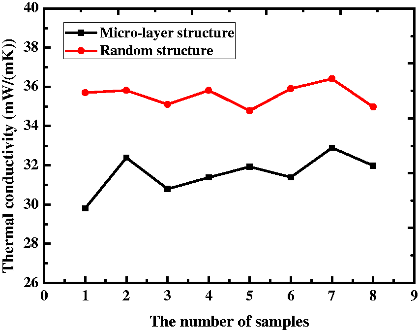
Conclusions
Glass fiber felts were fabricated by CSB process. Swing cylinders were designed to obtain a micro-layer structure. Increasing the oscillation frequency could reduce the wavelength of the trajectory of glass fibers leading to obtain the micro-layer structure. At the same time, the number of swing cylinders also contributed to obtain the micro-layer structure.
For the micro-layer structure, most fibers with two-dimensional distribution that spanned the entire glass fiber felts longitudinally could bear the tensile load leading to improve the tensile strength. However, this structure was not good for flexural rigidity of glass fiber felts. It was also found that the tensile strength of glass fiber felts improved with the increase of density and resin content. In addition, the mean thermal conductivities of glass fiber felts with random and micro-layer structures were 35.69 mW/m·k and 31.57 mW/m·k, respectively.
Footnotes
Declaration of Conflicting Interests
The author(s) declared no potential conflicts of interest with respect to the research, authorship, and/or publication of this article.
Funding
The author(s) disclosed receipt of the following financial support for the research, authorship, and/or publication of this article: The authors would like to thank the Priority Academic Program Development of Jiangsu Higher Education Institutions. This work was also supported by Major Achievements of Jiangsu Province (grant no. BA2013097), Development of Vacuum Insulation Panel of China Building Cooperative Research (grant no. 2015DFI53000), and by the NUAA Fundamental Research Funds (grant no. NS2015060). The first author also thanks the NUAA for financial support for PhD study at North Carolina State University.