
Abstract
Warp knitted spacer fabrics (WKSF) are technical textile structures that present special compression-elastic, air permeability, heat resistance and acoustic damping properties and because of that they are winning more application fields every day. In many of these fields, like the application for cushion structures in car seats and mattresses, the thick WKSF are of special interest and the mechanical behaviour of these structures needs to be known in detail but, although direct relationships exist between the textile technical and technological parameters and the mechanical behaviour of the mentioned structures, this characterisation is still being carried out experimentally. Analytical and numerical models have already been developed to study WKSF structures offering interesting contributions to a better knowledge of their behaviour and providing further research directions but there are some phenomena causing the particular and characteristic mechanical behaviour of these structures that have not been described yet. The aim of this paper is to give a better understanding of the mechanical behaviour of a single vertical spacer yarn of a thick WKSF under compression load by studying, with help of the finite elements method, the variations of the bending moment acting on the yarn during the compression process. In this article it has been found that these variations of the mentioned bending moment are the phenomena responsible for the characteristic mechanical behaviour of the WKSF structures.
Keywords
Introduction
Spacer fabrics with their special properties like compression-elasticity, heat resistance, air permeability and recyclability offer a lot of potential in different application fields (padding materials and cushion structures in car seats and mattresses, sport clothing, medical applications like knee braces, etc.). The thick warp knitted spacer fabrics (WKSF; thicknesses between 15 mm and 55 mm) are of special interest for cushion applications in car seats and recent research works revealed that they present better comfort and recyclability properties than polyurethane (PU) foams [1–3].
The special compression-elastic behaviour of WKSF and its relation to the textile parameters in the manufacturing process are topics of great interest for the designers of this kind of structures. In the industry it is required more and more the optimisation of the design process of WKSF through accurate predictions of the compression-elastic behaviour, allowing this to avoid the typical try and error testing routines. Different research works have been published in the last years describing the mechanical behaviour of WKSF and the mentioned relationships with the textile parameters [4–9] but there are phenomena producing this particular behaviour that have not been analysed yet. In this paper, the influence of the bending moment acting on the yarn during the compression process has been studied with help of numerical methods in order to provide a deeper knowledge of the special mechanical behaviour of WKSF when they are subjected to compression loads.
Structure definition and manufacturing technology
WKSF are three-dimensional textile structures composed of two parallel knitted fabrics united by a spacer yarns layer (see Figure 1) [4,10,11]. The spacer yarns layer plays the role of standing the compression loads and the two knitted fabrics hold the position of the spacer yarns along their surfaces.
Generic thick warp knitted spacer fabric.
Working on the basis of the loop formation technique, the three parts of the WKSF structure (the two knitted fabric surfaces and the yarns layer) are produced simultaneously in a raschel knitting machine. For the case of thick WKSF, the technology that permits the manufacturing of such thick structures (thickness between 15 and 55 mm) is the HighDistance® raschel machine. In comparison with traditional two-needle bar raschel machines, which were only capable to produce spacer fabrics with thicknesses up to 15 mm, the HighDistance raschel machines, through their electronic powered up yarn guides, achieve the before mentioned thickness range. A typical configuration of these machines is shown in Figure 2. Two knock-over comb bars define the theoretical thickness (Tt) of the spacer fabric and two needle bars move alternatively up and down to collect the yarns provided by the yarn guides [4,10–12].
Example of HighDistance® raschel machine.
After the warp knitting process, spacer fabrics are normally subjected to a heat-setting treatment, which consists in a thermal treatment of these structures to achieve a determined form and the subsequent fixing of this form. In this way, the structural stability of the WKSF is guaranteed. It is important to know that, due to the whole manufacturing process and its attached residual stresses, contractions in the three directions of the spacer fabric occur and obviously they have a high relevance for its mechanical behaviour.
In the production process of WKSF with the mentioned technology different textile technical and technological parameters can be set to achieve different structures with different geometries and mechanical properties. Some of the most important parameters to be set are the spacer yarn diameter and material, density and inclination angle of the spacer yarns, knock-over comb bar distance (see Figure 2), the dimensions of the spacer fabric and the needle gauge in the needle bars [4].
Reference model and motivation
An analytical model of the mechanical behaviour of WKSF has already been developed by Helbig [4]. In the mentioned model experimentally validated equations based on the second order beam theory [13] have been given. These equations describe the flexural buckling phenomenon occurring in spacer fabric structures working under compression loads. This analytical model represents a good characterisation of the compression-elastic behaviour of the structures of interest here but requires a correction function to accurately match the experimental data [4,10,11]. It means that there are still phenomena during the compression loading process that have not been reproduced by the proposed analytical expressions. Therefore, to achieve more accuracy in the prediction of the mechanical behaviour of WKSF a more detailed approach is required.
Nowadays, and thanks to the finite elements method (FEM), it is possible, knowing the geometry of the structure of interest here together with its material properties, attached loads, etc. to simulate its mechanical behaviour with an important accuracy grade. In comparison with analytical methods, FEM permits usually a more accurate characterisation of structures due to the fact that it requires a minor number of assumptions to be made. In this paper, a FE model of an isolated vertical spacer yarn has been developed to study the compression-elastic behaviour of this structure and find out phenomena that have not been considered analytically in Ref. [4] and that are difficult to evaluate experimentally. Note that the realisation of an experimental study of an isolated vertical spacer yarn is complicated because of the difficulty to manufacture WKSF with only strictly vertical spacer yarns (see Figure 1).
The reference compression process to study the compression-elastic behaviour of spacer fabrics is the standardised compression test defined by DIN EN ISO 3386-1 [14], therefore these test conditions have been reproduced to carry out the study of the spacer yarn flexural buckling.
Analytical characterisation of the compression-elastic behaviour of a vertical spacer yarn
In Helbig’s study [4], a model describing the relationship between the applied force on a vertical spacer yarn and its vertical deformation (ɛqD) during the compression loading process has been developed. The mentioned deformation (ɛqD) has been defined as a relative displacement (s) to the theoretical thickness of the spacer fabric (Tt), which, as noted before, is equal to the knock-over comb bar distance (see Figure 2). It is important to remember the fact that, after the whole manufacturing process, the spacer fabric experiences contractions in all directions and because of that the Tt and the real thickness (Rt) do not match. Therefore, and having defined the vertical deformation (ɛqD) as a relative displacement referred to Tt, it has to be noted that an initial vertical pre-deformation (ɛqD0) is always present before the loading process (see Figure 3). The geometrical position of the yarn is defined through the yarn length (lk), initial curvature radius (r0) and initial x coordinate of the middle point of the yarn (x0), being all of them easy to determine through the textile parameters [4].
Vertical spacer yarn’s initial position.
The most characteristic aspect of these textile structures referring to their compression-elastic behaviour is the fact that the spacer yarns at a determined deformation grade come in contact with the knitted surfaces (note that by “come in contact” it is being meant that a part of the vertical yarn length contacts the knitted surface). This leads to an important change in the behaviour curve and, because of that, the force versus deformation (ɛqD) curve representing the compression-elastic behaviour of the spacer yarn is divided in two zones: the free flexural buckling zone (FrFB), where the spacer yarn has not taken contact with the knitted surface yet (See Figure 4) and the forced flexural buckling zone (FoFB), where the yarn is contacting the knitted surface already. An important statement concerning the transition between FrFB and FoFB is that it always occurs under the assumptions (explained at the end of this chapter) of the analytical model of Helbig [4] for a ɛqD value of 0.363 (denoted as ɛqD_k), which can be easily obtained for an arbitrary value of the textile parameter Tt through the geometrical relationships [4].
Free flexural buckling (FrFB).
It must be mentioned that for FoFB two different and alternative approaches have been taken to define the compression-elastic behaviour: The first approach considers that the acting force changes its position along the X axis during the buckling process, meaning this that, in the spacer fabric, the previous yarn would take the force (F) placed at the first x position and the yarn matter of the study would take the next one (F’), placed at the last achieved contact point between yarn and knitted surface, with the consequence of a minor bending moment acting on the yarn free length (see Figure 5(a)). On the other hand, the second approach considers a force remaining its position, involving that a higher moment attached to the spacer yarn free length (see Figure 5(b)) [4].
Forced flexural buckling (FoFB).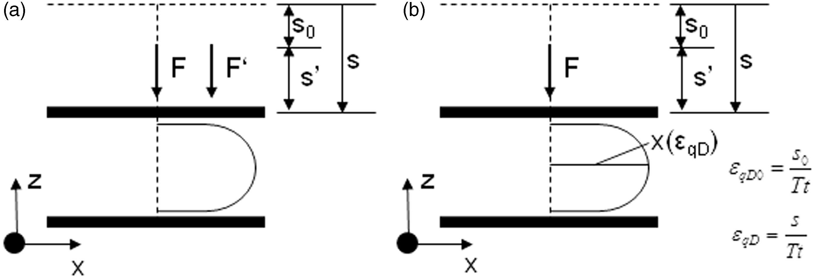
The equations employed by Helbig [4] that describe the compression-elastic behaviour of the spacer yarn during its buckling process are based on the beam theory. A second order theory has to be employed instead of a first order one to the study of buckling process due to the fact that the deformed state of the spacer yarn has to be considered to achieve realistic results in such instability problems [13]. The equation that describes the compression-elastic behaviour attached to FrFB is:

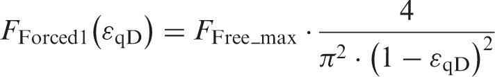

In the following, a list describing the items presented in the above shown equations and figures is provided:
FFree(ɛqD): force-ɛqD function during FrFB; E: Young’s modulus of the yarn; I: yarn section’s moment of inertia; ɛqD: varying vertical deformation; x(ɛqD) and r(ɛqD): varying x coordinate of yarn middle point and curvature radius (both function of ɛqD); Ffree_max: force value at the end of FrFB; Fforced 1(ɛqD): first approach force-ɛqD function during FoFB; Fforced 2(ɛqD): second approach force-ɛqD function during FoFB;
The analytical compression-elastic behaviour curve for a vertical spacer yarn can be seen in Figure 6 (note now that the compression force applied is always represented as a positive magnitude in this paper). It can be observed that, under the assumption of the first approach, an important change from a degressive stiffness trend into a progressive increasing one at the transition deformation ɛqD_k occurs. This does not happen for the model corresponding to the second approach, where the stiffness remains with a degressive, horizontal asymptotic trend after ɛqD_k.
Analytical compression-elastic behaviour curve of a vertical spacer yarn.
It is important to mention the assumptions made in this analytical model:
Linear elastic mechanical behaviour of the spacer yarn material; The spacer yarn free length keeps a circular form during the whole flexural buckling process. The analytical model assumes a circular deflection function (x(z)) as solution of the general Euler’s differential equation for buckling of columns [13] (see Figure 7 and equation (4)). Note that My(z), defined in the mentioned equation, is always the bending moment acting on the spacer yarn free length produced by a force placed at the last achieved contact point between yarn and knitted surface. This bending moment is the one considered to be acting under the assumptions of the first approach for the FoFB and during the FrFB. The yarn length (lk) is assumed to be equal to Tt. Due to the loop formation by the continuous yarn during the generation of the spacer yarns (i.e. before the contractions have taken place) the vertical yarns are not totally stretched along Tt in the real process. The connection between vertical spacer yarn and knitted surfaces has been realised through the consideration that the yarn is constrained by a floating bearing at its theoretical upper end and by a fixed bearing at its theoretical lower end. Euler’s differential equation for buckling of columns.


Description of FE model
For the mechanical study of the vertical spacer yarn compression-elastic behaviour a finite elements (FE) model generated with the commercial software ABAQUS 6.12 has been employed. In the following, the definition of the FE model based on the textile parameters is detailed.
Geometry
In real experimental compression tests of spacer fabrics (conducted under the conditions of DIN EN ISO 3386-1 [14]) the spacer fabric is compressed between two planar bodies much stiffer than the spacer fabric itself (see Figure 8 (a)) and therefore, in the FE model, with the aim to reproduce these conditions, two hexahedral bodies (with arbitrary dimensions) reproducing the compression bodies of the experimental test have been modelled and the knitted surfaces have been ignored and therefore not modelled (see Figure 8 (b)).
Geometry.
Concerning the yarn geometry, a monofilament with a circular section has been considered for this research. The textile parameters required to define it in this study case of a single vertical yarn are only the yarn diameter (d), Tt and real thickness (Rt). With these parameters it is possible to determine the yarn length (lk) and initial curvature radius (r0) [4]. To carry out the present study a thick WKSF with Tt = 34 mm, Rt = 31.246 mm and d = 0.2 mm has been taken and these parameter values lead to a yarn geometry with lk = 34 mm and r0 = 24.083 mm. Due to the symmetry of the geometry, constraints, loads and material properties only the half geometry has been modelled (see Figure 8 (b)).
Materials
The yarn material is polyethylene terephthalate (PET), a thermoplastic polymer from the family of the polyester. For the FE simulation only the Young’s modulus (E) and Poisson’s ratio (ν) are needed and they have values of 13.9 GPa [4] and 0.37 [15], respectively. Due to the fact that the dimensions of the yarn transversal section are very much smaller than the yarn length, the real material properties in the directions of the section plain would not provide more accuracy in the study of the flexural buckling and because of that an isotropic behaviour has been assumed for the yarn material. For the two compression bodies a standard steel (E = 210 GPa, ν = 0.3) has been taken. Both materials have been considered to have linear elastic mechanical behaviour.
Contact, boundary conditions and loads
Concerning the contact and boundary conditions, all the possible movements of the lower compression body have been constrained and for the upper compression body only the vertical displacement has been allowed, being the rest of the degrees of freedom blocked (the constraint conditions have been actually applied on determined surfaces of the compression bodies, not on the whole bodies). Between the yarn and the compression bodies bearing conditions (defined in ABAQUS through ‘hinge’ connections, which only allow the rotation on the Y axis) together with surface-to-surface contacts (‘hard’ contact with a generic friction coefficient of 0.1) have been defined (see Figure 9). In this way the boundary conditions of this FE model are consistent with the ones of the analytical model of Helbig [4].
Contact, boundary conditions and loads.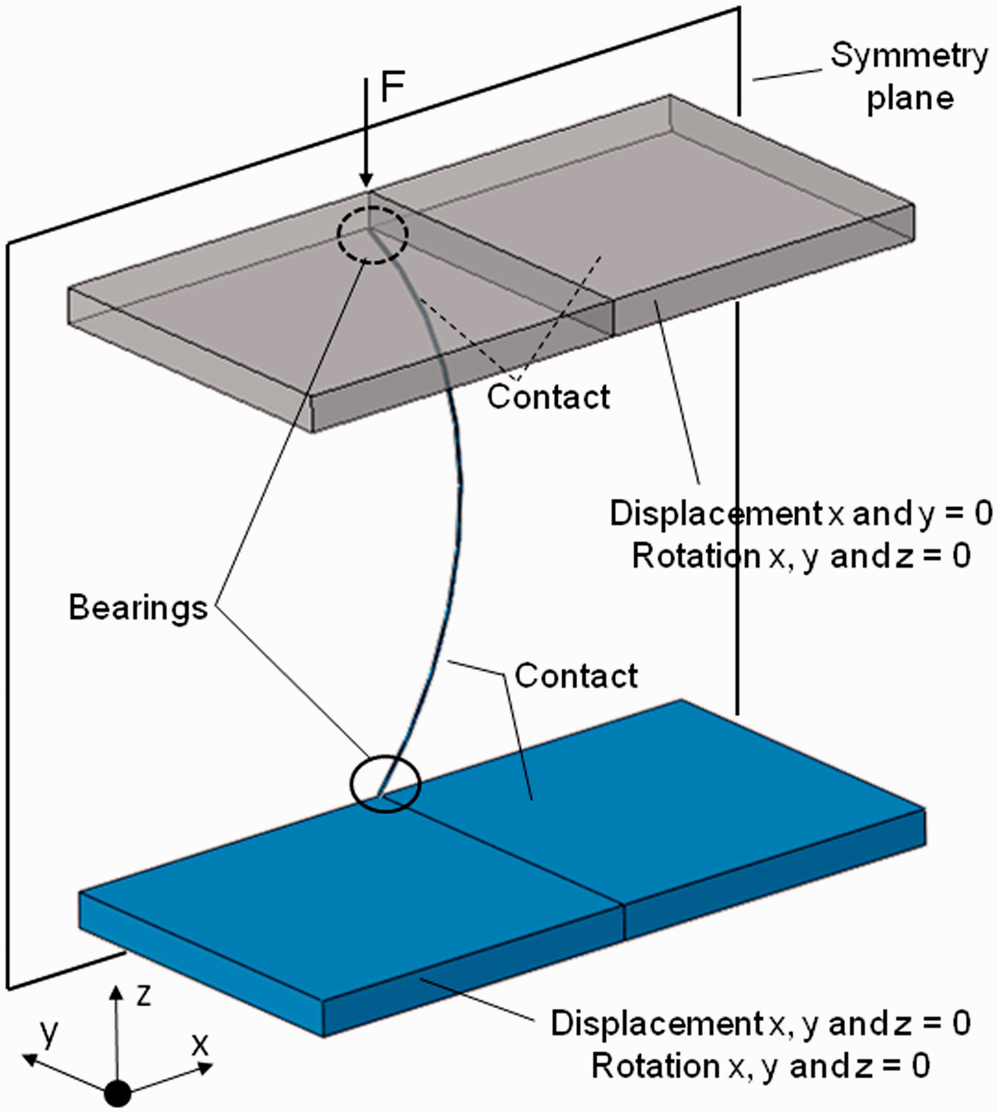
A matter of importance is to note that the upper compression body (defined under conditions consistent with Ref. [14]) is supported in the reality by a determined structure and it transfers the experienced moments to this structure and not to the spacer yarn, therefore its rotation degrees of freedom have been restrained in the FE model to reproduce these conditions. The only moment transferred to the spacer yarn free length in the test defined by DIN EN ISO 3386-1 [14] is the one denoted as My(z), defined in the Euler’s equation for the buckling of columns (see Figure 7 and equation (4)), and the FE model is consistent with this fact (as well as the analytical model of Helbig [4] under the consideration of the first approach for FoFB).
In the symmetry plane of the FE model, the correspondent symmetry condition has been defined. Considering the symmetry, a varying force from 0 N to 0.04 N (equivalent to 0.08 N for a whole geometry model) has been applied at the upper compression body (see Figure 9). Note that, knowing that all the bending moments (except My(z)) are transferred to the rotation restrictions of the compression bodies, the position of the force on the compression body can be arbitrary.
FE mesh
The whole model has been meshed with linear hexahedral FE elements (the quadratic hexahedral FE elements do not produce accurate results in contact problems [16]) with different elements sizes and locally refining at contact zones and along the yarn geometry (see Figure 10). The geometry has been remeshed several times, incrementing the refinement grade at each attempt, until a non-significant change in the results has been observed. A mesh with 17,170 nodes and 13,320 elements has been employed. The element sizes vary between 0.05 mm at the refined zones and 5.5 mm at less relevant zones.
Finite elements (FE) mesh.
FE simulation type
A static non-linear FE simulation has been carried out to study the mechanical behaviour of the mentioned system. The more appropriated numerical analysis method for this kind of simulations is `the implicit method, which guarantees static equilibrium between the internal forces and the external loads at the end of each load increment step in the simulation. Therefore, the implicit method has been used for the present study.
The direct linear equation solver of ABAQUS has been employed due to the fact that it is well suited for FE models with the size of the model matter of study in this paper.
Results and discussion
The applied compression force in dependence on the vertical deformation (ɛqD) for the analytical and FE models has been represented in the Figure 11. In the mentioned figure it can be observed that the two models predict a similar behaviour during FrFB but they show different transition values ɛqD_k. This occurs because in Ref. [4] it has been assumed a circular deflection (x(z)) as solution of the Euler’s differential equation for the buckling phenomenon in columns. The FE results show that, in fact, the spacer yarn presents a different and more complex deflection trend during the whole flexural buckling than the one assumed in the analytical model (see Figure 13). This different and more realistic deflection trend predicted by FEM involves that, for a determined value of the acting force at a determined instant of the flexural buckling process, the spacer yarn experiences a different bending moment My(z) than the one predicted by the analytical model and this leads to a different ɛqD value. On the other hand, it is important to note that the FE model confirms the occurrence of an important stiffness trend change (from degressive into progressive trend) at the transition deformation (ɛqD_k_FEM).
Compression-elastic behaviour curve of a vertical spacer yarn – analytical model versus finite elements (FE) model. Compression-elastic behaviour curve of a vertical spacer yarn – zones of interest. Deflection evolution along the flexural buckling process.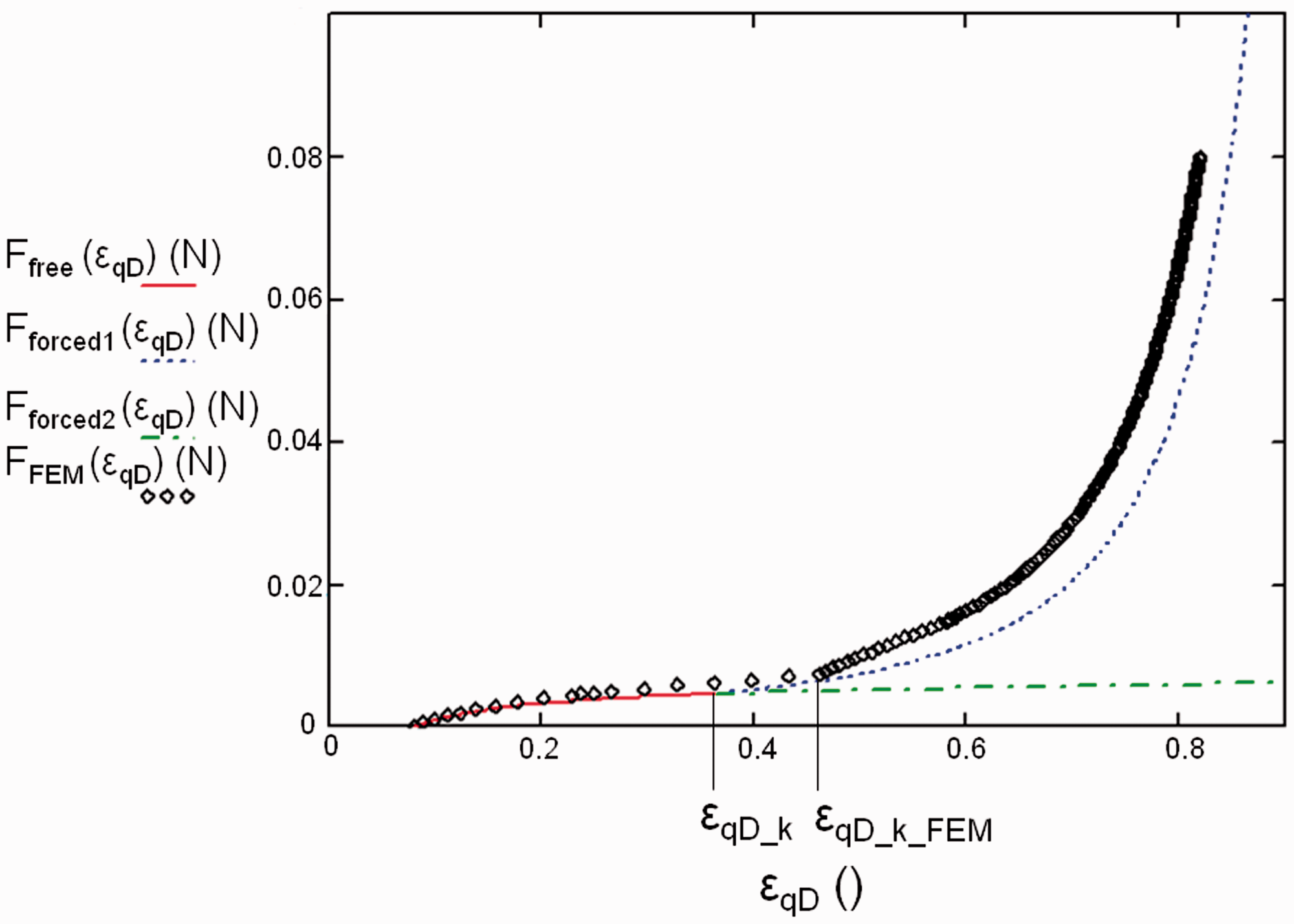


Referring to the first approach taken by Helbig [4] to study FoFB, it can be seen in Figure 11 that, again due to the different deflection function obtained with FEM, the spacer yarn shows a stiffer compression-elastic behaviour than the obtained one analytically in general. In Figure 12 an augmented view of the compression-elastic behaviour curve of the spacer yarn is plotted and it can be seen that there are different zones presenting different stiffness behaviours for both models (analytical and FEM). Four cases representing the principal zones of interest defined by four different load values (see Figures 12 and 13) are detailed now. In the zone (a), characteristic of low compression loads, both models predict FrFB. The FE results show a deflection (see Figure 13 (a)) that provides a stiffer behaviour (due to a minor My(z) acting on the yarn) than the analytically predicted one. The analytical stiffness increase observed in the zone (b) is produced by the transition between FrFB and FoFB, which leads to a reduction of the yarn free length (because of the contact of part of the yarn with the compression bodies) with the attached reduction of My(z). Looking at the FE results at this zone, it can be seen that this does not occur actually because ɛqD_k_FEM is not achieved yet and therefore no contact has happened yet. Increasing the load, FoFB is achieved (zone (c)) and, due to the contact and the consequent reduction of My(z), FEM predicts now a higher stiffness, i.e. a change from a degressive stiffness trend into a progressive one has happened. In the last zone (d), both models predict similar progressive growth of the contact zones (see Figure 13 (d)) between yarn and knitted surfaces with similar progressive stiffness trends but, due to the previous evolution, the two curves do not match and progress parallel to each other. It can be concluded that, observing that the predicted curve by FEM remains at the left side of the analytical one during the whole flexural buckling process, the spacer yarn behaves in a stiffer way than the predicted one analytically and that the variations of the bending moment My(z) during the compression process are responsible of it.
The assumption of a fixed position of the load F made in the second approach for FoFB by Helbig [4] involves the transmission of an additional moment to the spacer yarn due to the growing distance between the force application point and the yarn free length. This does not match the conditions described in Ref. [14] and therefore it is beyond the scope of this paper. In Figure 11, it can be seen how much the two models (second approach analytical model and FE model) disagree due to their different boundary conditions.
In last term it has been tested if the assumption of linear elastic material behaviour for the spacer yarn is acceptable and therefore the maximal principal strain values at the yarn middle section (this is where the higher values are reached, in this case by the third principal strain (ɛ3)) have been assessed to check if they reach a limit value of 1.5% (this value has been defined identifying the elastic field limit value of the strain in the stress–strain curve of the yarn material [4]). In Figure 14, it can be seen that values of 1.5% of the principal stresses are achieved for a ɛqD of 0.667 for this particular geometry. For higher values than the mentioned one the FE results of this model are not valid because plastic deformation would occur. The experience shows that this plastic behaviour only happens for cases of spacer fabrics with very high spacer yarn densities, where the yarns have no possibility to buckle in other planes. In the other case, the spacer yarns can avoid the plasticity by buckling in other planes. Therefore, the study of the phenomena occurring for high ɛqD values require more complex FE models including more spacer yarns in the geometry, elastic-plastic material behaviour, etc.
Maximal principal strain at vertical spacer yarn versus ɛqD.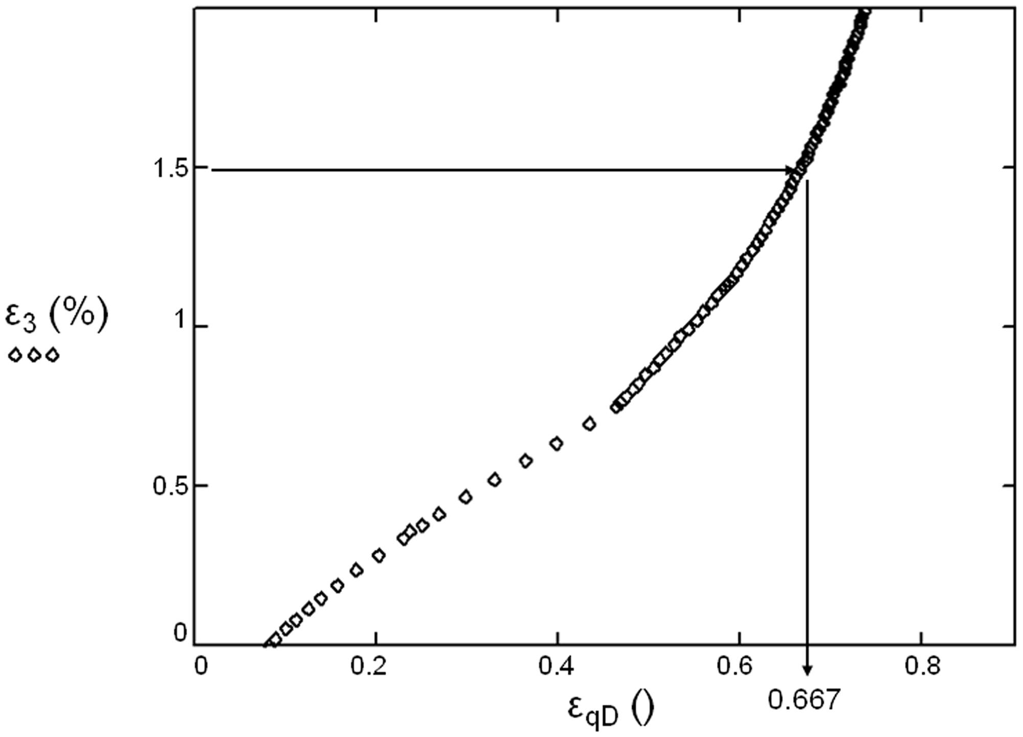
Conclusions
A FE model has been developed to study the compression-elastic behaviour of a vertical spacer yarn in a thick WKSF on the basis established by Helbig [4] in this research field. The FE analysis reveals a more complex deflection trend of the vertical spacer yarn than the supposed one in Ref. [4] with the direct consequence of a general stiffer compression-elastic behaviour of this kind of structure during the whole flexural buckling process. This phenomenon is one important reason justifying the need of a correction function in the analytical model of Helbig [4] for the general mechanical characterisation of WKSF.
This paper confirms the influence of the spacer yarn geometry and the contact between the spacer yarn and the knitted surfaces on the mechanical behaviour of vertical spacer yarns during the flexural buckling process. The innovative argument justifying this influence here is the presence of the bending moment My(z), defined by the Euler’s equation for the buckling of columns, that is changing during the buckling process (according to the yarn geometry and the contact conditions) and therefore making the mechanical response of the vertical spacer yarn so particular and characteristic. The knowledge of the effect of this bending moment on the mechanical behaviour of WKSF will help the designers to define textile parameter combinations targeting determined bending moment distributions along the spacer yarns in order to achieve application oriented mechanical behaviours of these structures.
On the other hand, a FE model with the characteristics of the one presented in this paper presents limitations concerning the compression-elastic behaviour characterisation attached to high ɛqD values, where the occurrence of phenomena like buckling in different planes or plastic deformation must be taken into account. The simplicity of this FE model allows a better understanding of some of the important mechanisms present in the flexural buckling of spacer yarns in thick WKSF with conscience that for a deeper knowledge of the mechanical behaviour of these structures more developed geometries, contact and boundary conditions, material modelling, etc. have to be carried out.
Footnotes
Funding
This work was performed within the Federal Cluster of Excellence EXC 1075 “MERGE Technologies for Multifunctional Lightweight Structures” and supported by the German Research Foundation (DFG). Financial support is gratefully acknowledged.