
Abstract
To address the challenges of high-intensity and broadband noise in diesel engine exhaust systems, multi-chamber reactive mufflers have been widely employed. However, complex acoustic coupling effects among internal components often render traditional linear superposition-based design methods ineffective. This study systematically investigates the acoustic characteristics of a complex three-chamber muffler by integrating the acoustic transfer matrix method, finite element numerical simulation, and orthogonal experimental design. An acoustic shielding effect was proposed based on the principle of acoustic impedance mismatch, thereby quantitatively elucidating the physical mechanism through which the upstream silencing unit attenuates the sound attenuation capability of the downstream unit by modifying the boundary conditions. Building upon this understanding, a “frequency band segmentation control” structural decoupling strategy is proposed, which employs non-uniform chamber lengths to suppress modal overlap and incorporates a low-perforation-rate inlet to enhance low-frequency reflection performance. Experimental results demonstrate that the optimized muffler achieves an average noise attenuation improvement of 6.16 dB(A) across the entire frequency range, while reducing exhaust backpressure by 8.98%. This research provides a reference for addressing coupling issues in complex acoustic systems.
Keywords
1. Introduction
With the acceleration of modern industrialization and urbanization, diesel generator sets have been widely adopted in emergency power supply, ship propulsion, and mobile power stations due to their high thermal efficiency and operational reliability.1,2 However, the intense exhaust noise generated during diesel engine operation not only contributes significantly to environmental pollution but also poses irreversible risks to human auditory function, cardiovascular health, and psychological well-being.3,4 In response to increasingly stringent environmental regulations and noise emission standards, the development of high-performance exhaust mufflers has become a critical challenge in internal combustion engine noise control. 5
Exhaust mufflers are primarily classified into three types: resistive, reactive, and resistive-reactive composite mufflers. Due to the degradation of porous materials under high-temperature and high-humidity exhaust conditions, resistive mufflers often suffer from performance deterioration. As a result, reactive mufflers—based on the principle of acoustic impedance mismatch—have become the preferred solution for diesel engine noise reduction.6,7 Conventional reactive mufflers attenuate noise by reflecting sound waves at cross-sectional discontinuities, typically employing Helmholtz resonators to target specific frequency bands. 8 To improve acoustic performance further, researchers have analyzed the acoustic impedance of perforated plates under grazing flow conditions 9 and examined the impact of baffle configuration on transmission loss in automotive mufflers.10,11 Among these components, perforated tube assemblies are extensively employed in complex muffler designs owing to their favorable aerodynamic performance and effective acoustic control capabilities. 12
To accurately predict the acoustic performance of mufflers, researchers have developed various theoretical and numerical methods. Early studies primarily relied on the transfer matrix method based on one-dimensional plane wave theory, which offers high computational efficiency but suffers from significant inaccuracies when modeling high-frequency higher-order modes and complex geometries.13,14 With advances in computing technology, the finite element method (FEM),15,16 boundary element method (BEM), 17 and computational fluid dynamics (CFD) 18 have become mainstream simulation tools. These numerical approaches enable precise prediction of sound field distributions within complex cavities and allow for the incorporation of flow velocity, temperature gradients, and viscous-thermal dissipation effects into sound propagation models.
In addition to conventional approaches, the field is advancing toward multi-objective optimization that balances weight reduction with acoustic performance. 19 Innovative designs, such as acoustic metamaterial-based mufflers 20 and ducts with porous liners, 21 have been explored to target specific frequency ranges. Moreover, the integration of machine learning for performance prediction 22 and the application of acoustic black holes 23 for vibration damping offer promising pathways for digital and structural noise control.
In structural optimization, statistical methodologies such as orthogonal experimental design 24 and the Taguchi method 25 are widely adopted in engineering practice due to their ability to identify key parameters with minimal experimental effort. Nevertheless, most existing studies focus on algorithm-driven searches for optimal geometric parameter combinations, often treating the muffler as a “black-box” system. This approach lacks a thorough investigation of the interaction mechanisms among noise reduction units in multi-chamber configurations.26,27 Furthermore, the modal coupling mechanism between different chamber lengths and characteristic wavelengths remains insufficiently understood, posing challenges in achieving balanced broadband noise attenuation, particularly in the mid-to-low frequency range typical of diesel engines. 28
Although classical impedance models, such as the one developed by Munjal and subsequent enhancements proposed by Li et al., have established a foundational transfer matrix framework for analyzing multi-chamber coupling, they primarily emphasize overall performance prediction and often overlook the localized performance degradation of individual chambers. To address this limitation, the present study introduces the concept of “acoustic shielding effect” as a diagnostic framework to quantitatively characterize the mutual impedance constraints that are typically oversimplified in conventional engineering practices. Focusing on a three-chamber reactive muffler used in diesel generator sets, this work investigates two critical aspects: (i) the quantitative characterization of the acoustic impedance coupling mechanism among the chambers, and (ii) the mitigation of modal overlap through structural decoupling strategies to enhance broadband acoustic performance across the full frequency spectrum.
2. Muffler theory
2.1. Transfer matrix method
In the one-dimensional acoustic performance analysis and experimental validation of mufflers, the Transfer Matrix Method (TMM) serves as the core theoretical framework. Under the assumption of plane wave propagation, each acoustic component within the muffler—such as expansion chambers, perforated tubes, and similar elements—can be modeled as a four-pole acoustic network. For any given acoustic element, the relationship between the inlet acoustic pressure p
in
and volume velocity u
in
, and the outlet acoustic pressure p
out
and volume velocity u
out
, is characterized by the transfer matrix


Transmission Loss (TL) is the primary metric for assessing the intrinsic acoustic performance of a muffler, defined as the difference between the incident and transmitted sound power levels. Assuming that the muffler outlet is terminated with a non-reflecting termination (i.e., anechoic termination), the transmission loss can be calculated from the overall transfer matrix parameters as follows:

2.2. The theoretical mechanism of the shielding effect
In complex multi-chamber muffler systems, the acoustic performance of any individual noise reduction component is not independent, but is interactively influenced by the acoustic impedance and boundary conditions of all adjacent components. This study defines the “acoustic shielding effect” as the reciprocal coupling mechanism among internal noise reduction units. This phenomenon arises when the impedance characteristics of a specific component modify the effective operating environment and energy distribution of other units, thereby preventing the system from achieving linear superposition of individual unit performances. To quantitatively assess this interaction within the classical TMM framework, the concepts of acoustic impedance mismatch and interface reflection coefficient are employed. Consider the connection interface between the i-th and (i+1)-th chambers within the muffler, denoted as x. The acoustic impedance upstream of this interface—corresponding to the outlet of the preceding unit—is defined as Z
up
, while the acoustic impedance downstream—at the inlet of the subsequent unit—is defined as Z
down
. Based on the definition of acoustic impedance Z=p/u, the acoustic pressure reflection coefficient R
x
at the interface can be expressed as:

When the design is suboptimal, in certain frequency bands—particularly at low frequencies—if Z
up
≫ Z
down
or the extreme values of the imaginary components of the two impedances are mismatched, the reflection coefficient |R
x
| approaches unity asymptotically. Consequently, most of the incident acoustic energy is reflected back toward the source by the front-stage structure, resulting in a significantly reduced transmission coefficient τ
x
into the rear-stage structure:

Based on the acoustic characteristics of the perforated tubes analyzed in this study, the perforation ratio P
r
of the inlet perforated tube directly determines the acoustic mass M
a
and acoustic resistance R
a
. For the acoustic impedance Z
perf
of the perforated neck, its imaginary component—representing the acoustic mass—is inversely proportional to the perforation ratio:

To facilitate the identification of performance bottlenecks, Shielding Loss (SL) is introduced as a conceptual diagnostic metric. SL quantifies the discrepancy between a component’s theoretical performance potential in isolation and its actual contribution within a coupled system. The definition is expressed as:

The primary role of SL is to serve as a theoretical benchmark for identifying “dormant” or underperforming components whose noise reduction potential is suppressed due to suboptimal impedance coupling. By minimizing SL through structural decoupling and frequency-segmentation control strategies, the acoustic shielding effect can be transformed from a detrimental interference into a cooperative coupling mechanism, thereby enhancing the broadband noise attenuation performance of the entire system.
2.3. Acoustic finite element analysis
Although the transfer matrix method offers advantages in elucidating one-dimensional physical mechanisms, the research subject of this study involves complex perforated tube arrays and cross-sectional discontinuities. In the high-frequency range of diesel engine exhaust, significant higher-order modal wave propagation and three-dimensional scattering effects occur, which cannot be accurately captured by traditional plane wave theory. Therefore, this study employs the finite element method (FEM) to develop a three-dimensional numerical model. The medium inside the muffler is assumed to be a homogeneous, inviscid, ideal fluid undergoing small-amplitude acoustic disturbances, and the internal sound field is governed by the frequency-domain Helmholtz equation:

This approach compensates for the TMM’s inability to account for three-dimensional geometric details and provides a high-precision computational platform for subsequent full-frequency performance prediction and structural parameter optimization.
3. Model establishment and validation
This study focuses on the exhaust muffler of a specific diesel generator set as the research object, with its original structure illustrated in Figure 1. The muffler features a three-chamber reactive configuration, primarily comprising an inlet perforated tube, the first expansion chamber, perforated inner tubes, the second expansion chamber, an inner tube array, the third expansion chamber, and an outlet perforated tube. The gas flow path is as follows: exhaust gas enters the first expansion chamber via the inlet perforated tube and subsequently splits into two streams. One portion flows directly to the third chamber through two perforated inner tubes, while the other bypasses into the second chamber through the perforations in the pipe wall, eventually converging in the third chamber through four evenly distributed inner tubes before discharge. Schematic diagram of the exhaust muffler structure for matching.
According to GB/T 4759-2017, the noise at the exhaust pipe outlet of the diesel engine was measured using a B&K 2250 sound level meter. The measurement setup is illustrated in Figure 2(a), and the resulting exhaust noise spectrum is presented in Figure 2(b). The results show that the diesel engine noise is predominantly distributed between 100 Hz and 3000 Hz, with high sound pressure levels across both low and high frequency ranges. Notably, the frequency bands from 250 Hz to 1000 Hz and around 1600 Hz exhibit particularly prominent peaks. Therefore, the designed and optimized exhaust muffler should achieve effective noise attenuation within these critical frequency ranges. Noise measurement point layout and 1/3-octave spectrum of diesel engine exhaust noise: (a) Measurement point layout; (b) 1/3-octave spectrum of exhaust noise.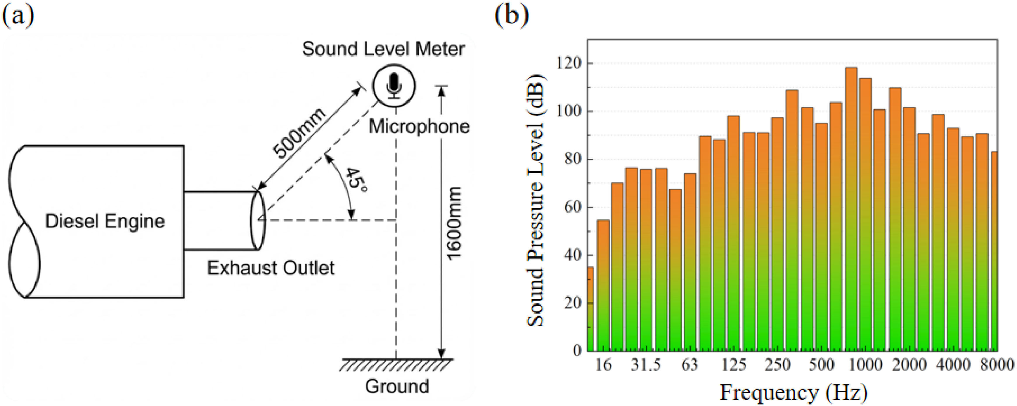
Given the complexity of the physical structure and the requirements for computational efficiency in finite element analysis, the following assumptions and simplifications were made when establishing the acoustic simulation model: welding bead height, bending radii, and assembly tolerances during sheet metal fabrication were neglected; the hole distribution on the perforated plates was assumed to be uniform, with burrs and minor deviations in hole diameter ignored. The connection between the perforated tube and the partition was modeled as a rigid junction without acoustic leakage. The medium inside the muffler was assumed to be uniform, isotropic, ideal air, and the effects of sound speed stratification due to exhaust temperature gradients were not considered in this study.
The three-dimensional model of the exhaust muffler was imported into the Pressure Acoustics module of COMSOL. The inlet boundary was set to plane wave radiation with a unit incident pressure amplitude of 1 Pa; the outlet was configured as a non-reflecting boundary condition, simulating a fully anechoic termination to enable accurate computation of transmission loss. The muffler shell and internal partitions were assigned as hard acoustic boundaries—i.e., with zero normal velocity—and wall absorption and structural vibration effects were disregarded.
To ensure convergence and accuracy in high-frequency acoustic simulations, the mesh element size was determined based on the wavelength corresponding to the maximum frequency of interest. The maximum element length, Lmax, should satisfy the following criterion: Cross-sectional view of the computational mesh.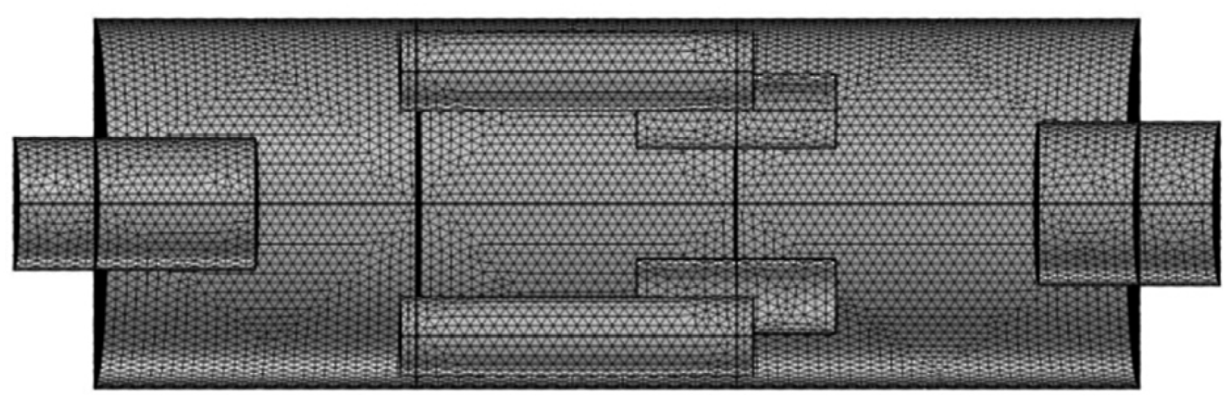

To validate the accuracy of the numerical model, a transmission loss test bench was established based on the dual-load method in accordance with GB/Z 27764-2011,
29
30
and the analytical solution for transmission loss was derived using one-dimensional plane wave theory. The experimental setup for acoustic performance testing of the exhaust muffler under the dual-load method is illustrated in Figure 4(a), while the experimental measurements, numerical simulation results, and theoretical calculations are presented in Figure 4(b). It can be observed that the simulation and theoretical values exhibit strong agreement in the low-frequency range but begin to diverge in the mid-to-high frequency range. This discrepancy arises because one-dimensional theory fails to accurately account for three-dimensional sound field scattering and high-order mode propagation at higher frequencies, particularly within the complex internal geometry of the three-chamber muffler. The overall trends of the experimental and simulation results are in good agreement across the entire frequency range, with an average relative error of 17.82%. The primary sources of deviation include the assumption of rigid boundaries in the numerical model, the use of an ideal fluid approximation, and potential manufacturing imperfections such as internal weld defects or connection gaps in the physical prototype. Considering that the acoustic performance evaluation of diesel engine exhaust mufflers primarily emphasizes broadband noise attenuation, minor discrepancies at specific frequencies are generally acceptable. Therefore, the developed acoustic finite element model is capable of effectively predicting the muffler’s acoustic performance. Schematic diagram and comparison of transmission loss measurement for the matched muffler: (a) Schematic diagram of transmission loss measurement; (b) Comparison of experimental, simulation, and theoretical results.
4. Structural parameter sensitivity analysis
4.1. Orthogonal experimental design
Due to the complex acoustic-vibration coupling characteristics in multi-chamber exhaust mufflers, the acoustic performance of each silencing unit is often interactively influenced by the boundary conditions imposed by adjacent chambers. Traditional one-factor-at-a-time methods are inadequate for capturing parameter interactions, while full parameter enumeration is computationally expensive. To efficiently identify key design variables without compromising computational accuracy, this study employs the Orthogonal Experimental Design (OED) method.
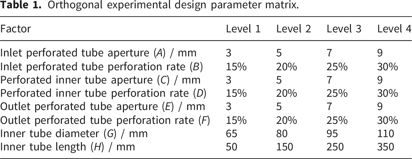
Orthogonal experimental design parameter matrix.
4.2. Parameter sensitivity analysis
Intuitive analysis of orthogonal experimental results.
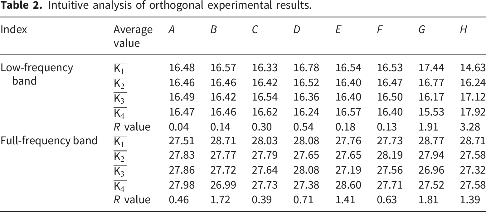
Table of significance levels for each design variable.
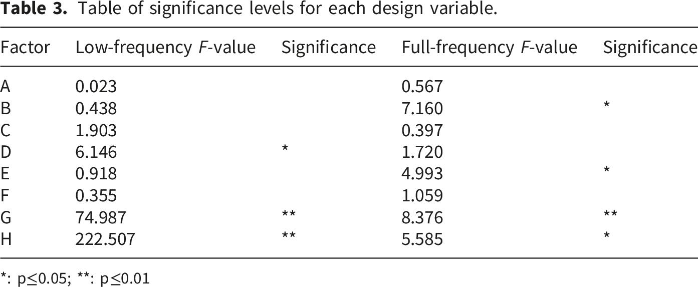
*: p≤0.05; **: p≤0.01
Through statistical analysis of the orthogonal experiments, it was determined that the inner tube structural parameters G and H are key factors common to both the full frequency band and the low-frequency band, whereas the perforation rate parameters B, D, and E exhibit notable frequency band selectivity. It should be noted that the low sensitivity of certain parameters, such as A and C, does not necessarily imply a lack of physical contribution; rather, it may result from the acoustic shielding effect within the multi-chamber structure.
5. Shielding effect analysis
The significant differences based on the orthogonal test results and the single-factor sensitivity analysis indicate that the acoustic performance of the complex multi-chamber muffler is not a linear superposition of the characteristics of each unit. There is a strong complex shielding effect among the muffler units, that is, the impedance characteristics of the front acoustic components restrict the propagation and excitation of sound waves to the rear, resulting in the masking of the potential noise reduction efficiency of the rear components. This section systematically analyzes the impedance-based coupling mechanism among structural parameters within the classical TMM framework, elucidating how the shielding effect governs acoustic interactions in multi-chamber configurations.
5.1. Analysis of the acoustic shielding mechanism
The variance analysis of the orthogonal test indicates that the perforation rate of the inlet perforated tube (B) significantly influences the full-frequency-band noise reduction performance, whereas the perforation rate of the inner tube (D) primarily governs low-frequency band performance. However, as illustrated in Figure 5, the transmission loss curves corresponding to different perforation rates exhibit substantial overlap in the low-frequency range, with a noticeable divergence emerging only above 1000 Hz. This behavior originates from the complex impedance coupling mechanism described by Equation (6). As the first acoustic load in the system, the impedance characteristics of the inlet perforated tube directly determine the acoustic energy injection efficiency and establish the system’s boundary conditions. When the inlet perforation rate (P
r
) is low, the acoustic mass (M
a
) of the perforation neck increases significantly, leading to a high-reactance characteristic of the inlet impedance and forming an “acoustic barrier.” According to Equation (5), the magnitude of the acoustic pressure reflection coefficient |R
in
| approaches unity, resulting in most low-frequency energy being reflected back to the source. This shielding effect renders downstream resonant units acoustically “dormant” due to insufficient excitation energy. Only through impedance optimization to mitigate upstream blockage can the inherent noise reduction potential of downstream units be effectively activated in the overall TL response. Transmission loss curves of the matched muffler under different perforation rates: (a) Comparison of inlet perforated tube perforation rates; (b) Comparison of perforated inner tube perforation rates.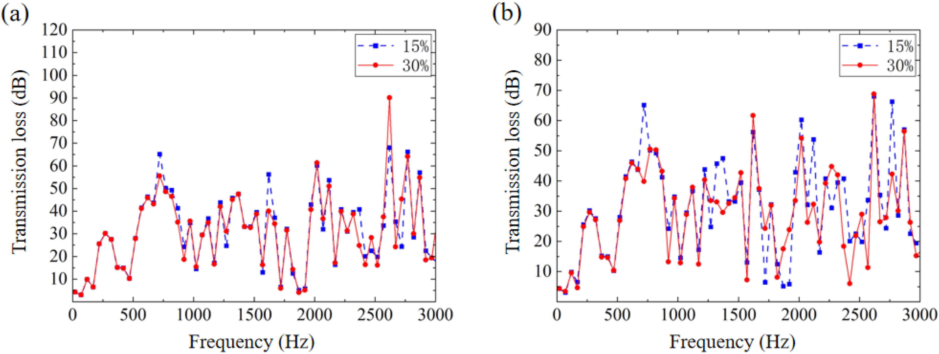
In the final optimized design, this principle is implemented as a “strong reflection priority” strategy, enabling targeted enhancement of low-frequency noise attenuation.
The inner tube in the multi-chamber structure serves a dual physical function, acting simultaneously as a transmission channel and as the neck of a quasi-Helmholtz resonator. As illustrated in Figure 6, single-factor analysis reveals that variations in the inner tube’s geometric parameters (G, H) primarily induce spectral fluctuations in the mid-to-high frequency range. This observation further elucidates the underlying physical mechanism of “resonant frequency masking.” The natural frequency f
r
of the resonant system formed by the inner tube and the downstream cavity is precisely governed by the following equation: Transmission loss curves of the matched muffler under variations in inner tube parameters: (a) Comparison of different inner tube diameters; (b) Comparison of different inner tube lengths.

In a complex coupled environment, the upstream chamber functions as a low-pass filter. If the tuning frequency f r of the inner tube lies beyond the cutoff frequency of the upstream chamber or coincides with a standing wave node, its specific resonant mode becomes suppressed. Consequently, in the absence of global impedance matching, the low-frequency noise reduction potential of the inner tube is effectively masked by reflected waves from upstream components. However, under multi-parameter collaborative optimization in the orthogonal test, an appropriate parameter configuration successfully activates these otherwise dormant resonant modes, demonstrating that the performance efficacy of the inner tube is fundamentally governed by the reciprocal coupling conditions among all internal components.
The outlet perforated tube primarily influences high-frequency performance above 2000 Hz, as illustrated in Figure 7. Unlike the inlet’s reflection-based mechanism, the outlet perforated tube affects the radiation and dissipation of high-frequency waves by modifying the acoustic admittance at the termination. Transmission loss curve of the matched muffler under different outlet perforated tube hole diameters.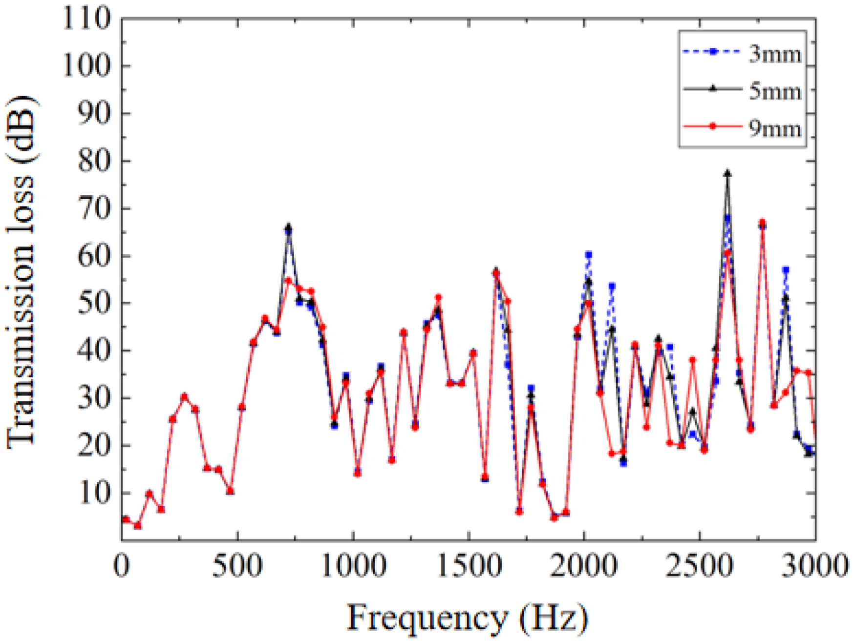
As frequency increases and the sound wavelength λ approaches or becomes smaller than the perforation diameter d, viscous friction and thermal conduction effects within the apertures diminish, leading to a change in the real part of the acoustic impedance (i.e., acoustic resistance). With increasing hole diameter, the acoustic transmission efficiency of the perforated plate improves, facilitating the direct radiation of high-frequency sound waves from the muffler in the form of plane waves, thereby reducing high-frequency transmission loss. To preserve high-frequency noise attenuation, a small hole diameter design is recommended to introduce sufficient acoustic damping and leverage the diffraction effect of the micro-perforations for enhanced high-frequency scattering.
5.2. Multi-chamber coupling characteristics
Analysis scheme for the coupling effect of cavity length.
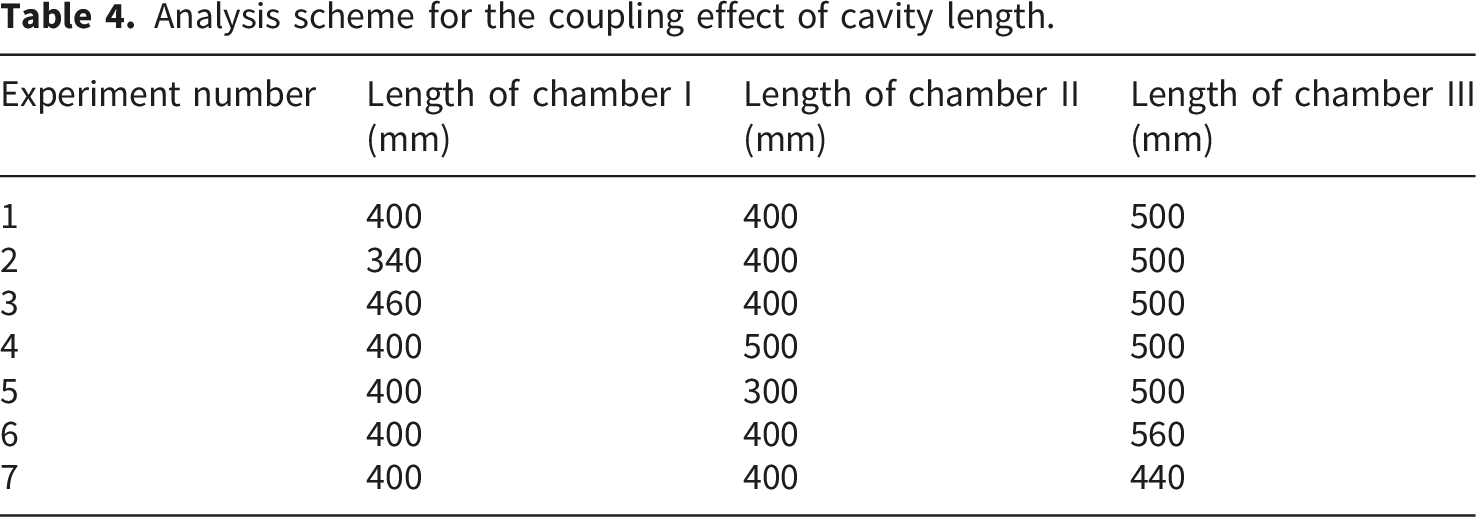
As the unit directly connected to the inlet, the first chamber predominantly governs the mid- and low-frequency bands. As illustrated in Figure 8(a), reducing the cavity length from 400 mm to 340 mm significantly enhances noise reduction performance within the 500 Hz to 1000 Hz range. The underlying physical mechanism is that shortening the cavity length shifts the corresponding quarter-wavelength resonance frequency toward higher frequencies, thereby avoiding the low-frequency core region where diesel engine exhaust energy is concentrated and improving the system’s impedance matching characteristics. The second chamber, serving as an intermediate transition unit, is strongly influenced by the coupling between upstream and downstream acoustic fields. As illustrated in Figure 8(b), variations in its length induce significant fluctuations within the 1000 Hz to 2000 Hz frequency band. When optimized to 400 mm, destructive interference is achieved through the generation of secondary reflection waves, effectively mitigating silencing valleys caused by modal overlap and resulting in a smoother spectral response. The third chamber primarily functions to dissipate residual noise above 2000 Hz. As shown in Figure 8(c), increasing the cavity length to 560 mm substantially enhances high-frequency attenuation performance. The extended propagation path increases the number of sound wave reflections, intensifies energy dissipation due to viscous-thermal effects, and promotes the formation of multiple high-frequency standing wave nodes, thereby suppressing the outward radiation of high-frequency turbulent noise. Transmission loss of the muffler under different chamber lengths: (a) Effect of chamber I length on transmission loss; (b) Effect of chamber II length on transmission loss; (c) Effect of chamber III length on transmission loss.
In conclusion, this study has established a tuning strategy based on non-uniform cavity lengths. This frequency band segmentation design effectively overcomes the inherent resonance overlap limitation of conventional equal-length cavity configurations and enables systematic synergy among low-frequency impedance reflection, mid-frequency modal interference, and high-frequency viscous dissipation.
6. Muffler optimization design and verification
6.1. Optimized design scheme
Based on the sensitivity analysis results from orthogonal experiments and the theoretical mechanism of the multi-chamber acoustic shielding effect, this study proposes a systematic optimization design scheme for the diesel engine exhaust muffler in emergency power vehicles. Considering the spatial constraints imposed by the engine room layout and the dimensional limitations of the sound insulation enclosure, the diameters of the inlet tube, expansion chamber cross-section, exhaust tube, and the total length of the muffler are kept constant.
The specific structural optimization parameters and their corresponding physical mechanism interpretations are as follows. (1) The perforation rate of the inlet perforated tube was reduced from 30% to 15%. Although a lower perforation rate increases the inlet acoustic impedance and induces an acoustic shielding effect, this design implements a “strong reflection priority” control strategy grounded in impedance mismatch theory. Reducing the perforation rate significantly enhances the acoustic mass and the real part of the acoustic impedance at the inlet, causing the acoustic pressure reflection coefficient to approach unity. This configuration leverages the high-impedance interface to reflect the majority of low-frequency incident acoustic energy back toward the source, rather than allowing transmission into the muffler interior. Results from the orthogonal experiments confirm that, under a full-frequency noise reduction objective, the 15% perforation rate yields a higher average transmission loss compared to the high-perforation-rate configuration. (2) The original structural symmetry is disrupted by adjusting the lengths of the three expansion chambers to 340 mm, 400 mm, and 560 mm for the first, second, and third chambers, respectively. The non-uniform distribution of cavity lengths is designed to induce destructive interference at modal overlap frequencies, thereby smoothing the spectral response and ensuring broadband acoustic performance. Shortening the cavity length of the first chamber shifts its quarter-wavelength resonance frequency to a higher frequency band, thereby effectively filling the transmission loss valley in this frequency range. The second chamber acts as an intermediate transition unit; its specific length is tuned to induce destructive interference within the 1000 Hz–2000 Hz range, thereby suppressing TL fluctuations caused by modal coupling between upstream and downstream stages. The third chamber is elongated to extend the propagation path and increase the number of reflections for high-frequency sound waves, enhancing viscous-thermal dissipation effects and specifically targeting the attenuation of turbulent regeneration noise above 2000 Hz. (3) The inner tube diameter was set to 65 mm, its length shortened to 50 mm, arranged as an array of four parallel tubes. According to Equation (10), this configuration effectively tunes the Helmholtz resonance frequency to target dominant low-frequency noise components. The short-tube design mitigates the low-frequency resonance masking effect associated with long transmission lines and instead enables behavior characteristic of a sound hole array, complementing the high-frequency dissipation of the extended cavity and thereby achieving effective broadband performance balance. The perforation rate of the inner perforated tube is reduced to 20%, while the outlet perforated tube features a hole diameter of 3 mm and a perforation rate of 15%. This micro-perforation design increases the real part of the acoustic impedance, enhances scattering attenuation, and leverages micro-perforation diffraction to suppress high-frequency turbulent noise.
Using the acoustic finite element model established in Section 3, the optimized muffler was three-dimensionally modeled, meshed, and numerically simulated. The transmission loss curves of both the optimized and original mufflers are presented in Figure 9. It can be observed that the transmission loss of the optimized design is improved across nearly the entire frequency range. The noise reduction performance is particularly enhanced between 700 Hz and 900 Hz, and between 1250 Hz and 2000 Hz, achieving average attenuation levels of 33.24 dB and 18.59 dB, respectively. The overall average noise reduction across the full frequency band has increased by 8 dB. Thus, the optimized exhaust muffler demonstrates significantly improved acoustic performance. Comparison of transmission loss before and after optimization of the matched muffler.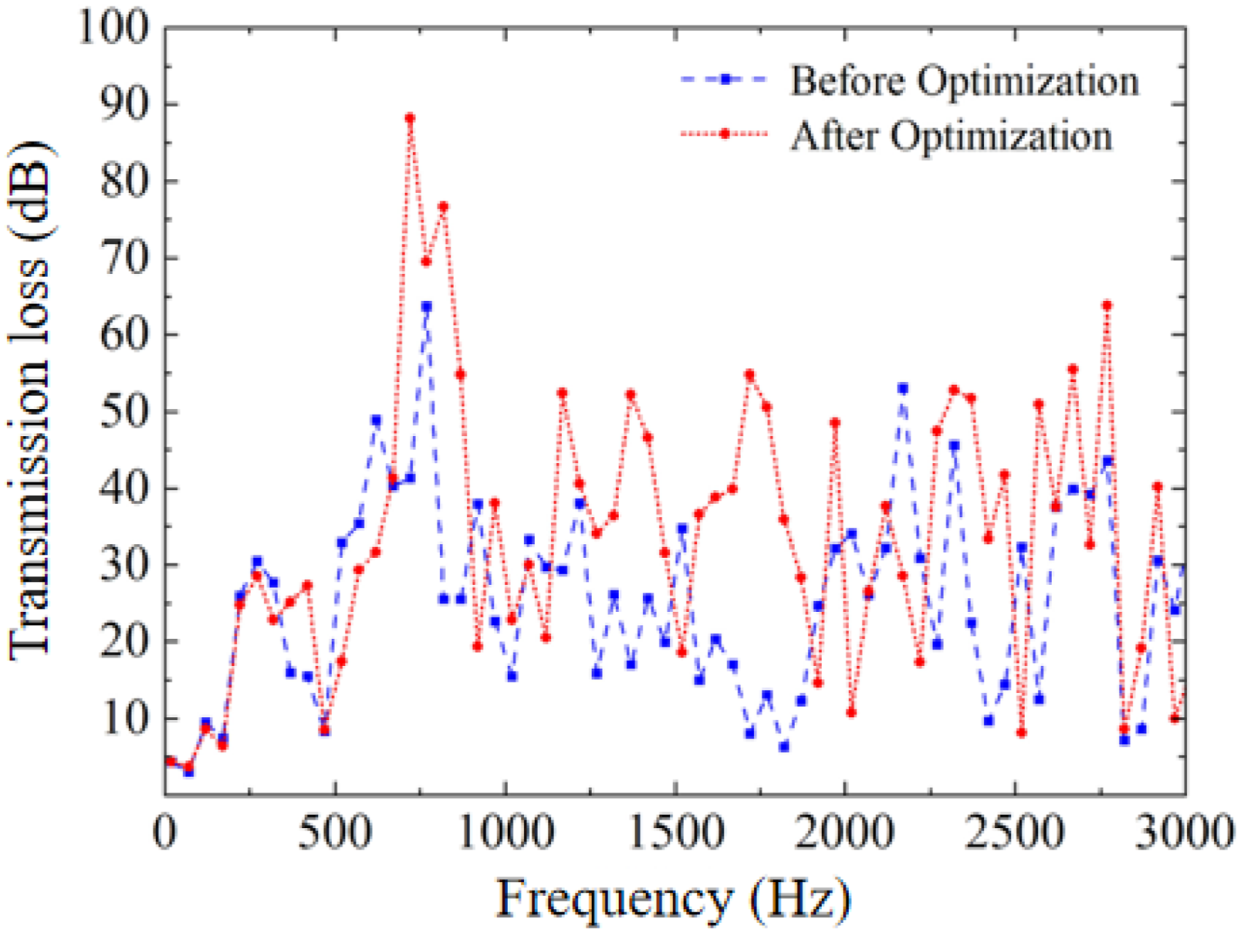
6.2. Acoustic and aerodynamic performance analysis
As there are two prominent sound pressure level peaks near 800 Hz and 1650 Hz in the diesel engine exhaust noise spectrum, the sound pressure level amplitude cloud maps at 820 Hz and 1670 Hz—before and after optimization of the matched muffler—were further simulated, as shown in Figure 10. Sound pressure level distribution contours of the matched muffler: (a) At 820 Hz before optimization; (b) At 820 Hz after optimization; (c) At 1670 Hz before optimization; (d) At 1670 Hz after optimization.
It can be observed that the optimized matched muffler exhibits a significant sound pressure level gradient, indicating effective attenuation of noise as it passes through the muffler. Each chamber and its internal noise reduction components function as intended, demonstrating that the design of chamber dimensions and structural parameters of the noise reduction units is rational and that the multi-chamber coupling effect is well realized.
To evaluate the impact of the muffler optimization scheme on the exhaust back pressure of the diesel engine, a three-dimensional numerical model was developed for CFD analysis. The Realizable k-ε turbulence model was employed, with the inlet boundary condition specified as a velocity inlet, the internal walls set to no-slip wall conditions, and the outlet boundary condition defined as a pressure outlet. The pressure distribution contours of the exhaust muffler before and after optimization are presented in Figure 11. It can be observed that under the rated operating condition, the pressure loss of the exhaust muffler decreases from 1.67 kPa to 1.52 kPa after optimization, representing a reduction of 8.98%, which meets the diesel engine’s specified pressure limit requirements. This result confirms that the optimized muffler design not only preserves acoustic performance but also contributes to improved engine efficiency and fuel economy. Pressure distribution contours of the matched muffler: (a) Before optimization; (b) After optimization.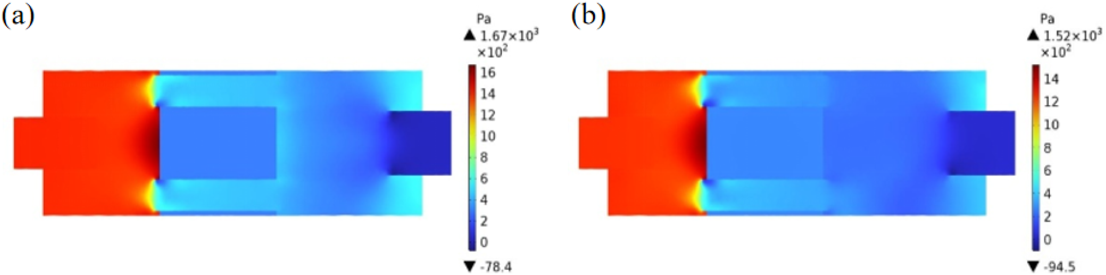
6.3. Validation of the optimization scheme
To evaluate the acoustic performance of the optimized exhaust muffler, a prototype was fabricated and subjected to experimental testing. In accordance with relevant testing standards, a comparative test method was employed to assess the muffler’s performance. With test conditions—including ambient temperature, relative humidity, and background noise—kept consistent, the exhaust mufflers before and after optimization were sequentially installed on the exhaust system of the same diesel engine model, as illustrated in Figure 12(a). A calibrated Brüel & Kjær Type 2250L precision sound level meter was used to measure the noise spectrum at the exhaust port in 1/3-octave bands, as shown in Figure 12(b). The sound pressure level spectra before and after optimization are compared in Figure 12(c), while Figure 12(d) quantifies the corresponding insertion loss improvements. It can be observed that the optimized exhaust muffler achieves significant noise attenuation in the characteristic frequency bands: the sound pressure level at the center frequency of 800 Hz is reduced by approximately 10 dB(A), and the reduction at 1600 Hz reaches about 8 dB(A). Given that the peaks of the diesel engine exhaust noise spectrum are concentrated in the 250 Hz–1000 Hz band and around the 1600 Hz center frequency, the noise reduction performance of the optimized muffler aligns well with these spectral characteristics. From a full-spectrum perspective, the average noise reduction increases by approximately 6.16 dB(A) after optimization, demonstrating enhanced broadband noise suppression capability. Comparative test of the acoustic performance of the exhaust muffler before and after optimization: (a) Schematic illustration of the muffler installation configuration; (b) Schematic of sound pressure level measurement at the exhaust port; (c) Comparison of noise sound pressure levels at the outlet; (d) The insertion loss improvement achieved through the proposed modification.
Although the specific optimal parameters derived in this study are tailored to a particular diesel engine muffler, the underlying physical insights and design methodology exhibit broader engineering applicability. The “acoustic shielding effect” framework, grounded in classical principles of impedance mismatch and boundary-condition coupling, serves as a universal diagnostic tool for identifying performance bottlenecks in multi-stage reactive mufflers. Moreover, the frequency band segmentation control strategy—achieved through non-uniform chamber length distributions to mitigate modal overlap—provides a scalable design approach applicable to a wide range of target frequency bands in internal combustion engine systems. The sensitivity rankings obtained via OED further offer a general guideline for prioritizing structural modifications in complex acoustic systems. Future work will investigate the robustness of this shielding mechanism under varying flow Mach numbers and temperature gradients to enhance the generalizability of the current findings.
7. Conclusion
To address the complex acoustic coupling and parametric conflicts in multi-chamber reactive mufflers, this study integrates the TMM, FEM, and OED to systematically investigate the internal interaction mechanisms. The main conclusions are summarized as follows:
This study demonstrates that muffler performance cannot be represented as a linear superposition of individual unit contributions but is instead governed by reciprocal acoustic coupling among components. Specifically, the impedance characteristics of upstream elements—such as an inlet with a low perforation rate—significantly alter the boundary conditions for downstream stages. This impedance mismatch may suppress the noise reduction potential of downstream units (shielding effect) or can be strategically leveraged to enhance low-frequency reflection through the formation of an “acoustic barrier.”
A structural decoupling approach based on non-uniform cavity length distribution (340 mm, 400 mm, 560 mm) is proposed. This configuration effectively mitigates modal frequency overlap inherent in conventional designs, enabling coordinated control across target frequency bands: low-frequency impedance matching, mid-frequency interference suppression, and enhanced high-frequency viscous-thermal dissipation.
Simultaneous improvements in acoustic performance and aerodynamic efficiency have been achieved. Finite element analysis, experimental validation, and computational fluid dynamics (CFD) simulations confirm that the optimized configuration—incorporating a low-perforation-rate inlet, a 50 mm short inner tube array, and a small-aperture outlet—achieves an average noise attenuation improvement of 6.16 dB(A). Concurrently, the streamlined flow path reduces exhaust backpressure from 1.67 kPa to 1.52 kPa, corresponding to an 8.98% reduction.
The engineering effectiveness of the proposed optimization method has been experimentally validated. Field measurements indicate that noise attenuation at key characteristic frequencies—800 Hz and 1600 Hz—increased by approximately 10 dB(A) and 8 dB(A), respectively. The optimization approach developed in this study, based on the analysis of acoustic shielding effects, provides a practical framework for addressing acoustic coupling challenges in mufflers with complex structural configurations.
While the optimization method proposed in this study has demonstrated significant effectiveness, certain limitations must be acknowledged. The acoustic finite element model assumes a uniform medium and does not account for sound speed stratification induced by exhaust temperature gradients. Furthermore, the CFD analysis was conducted under steady-state conditions, whereas real-world diesel engine exhaust is inherently characterized by pulsatile flow. Future work will focus on developing coupled thermo-acoustic models and investigating the muffler’s dynamic performance under unsteady flow conditions to provide more accurate guidance for the design of complex acoustic systems.
Footnotes
Author contributions
Funding
The authors disclosed receipt of the following financial support for the research, authorship, and/or publication of this article: This research is supported by a horizontal research project.
Declaration of conflicting interests
The authors declared no potential conflicts of interest with respect to the research, authorship, and/or publication of this article.
Data Availability Statement
Data will be made available on request.