
Abstract
The purpose of this paper is to improve the emission performance of diesel engines. A novel exhaust purification muffler was proposed and designed. The flow field characteristics of the exhaust purification muffler were studied based on the finite volume method, the pressure loss of the exhaust purification muffler was 3315 Pa, and the pressure loss of the exhaust purification muffler was just 2% higher than the original muffler. Then, a three-dimensional numerical simulation model was established and used to investigate the effect of different expansion ratio, cavity length ratio, and ratio of length to diameter on the flow field characteristics in an exhaust purification muffler of diesel engine. The study was shown that the porous media (ceramic foam) had a great influence on the flow field distribution, where the air flow velocity was stable and the pressure distribution was trapezoidal, having a good pressure reduction and deceleration effect. With the increase of the expansion ratio parameter, the airflow cross-section area changed when air entered into the inlet silencing cavity, which had great influence on the velocity field and the pressure loss. Because of the improvement of cavity length ratio parameter, the flowing distance in the inlet silencing increased, which caused more local turbulence and pressure fluctuation. Also with the increase of the ratio of length to diameter parameter, the volume of inlet silencing chamber and the air flow space increased. The change of the structural parameters of each scheme had a certain influence on the pressure loss. The maximum pressure loss changing value among the expansion ratio schemes was 878 Pa, then the maximum pressure loss changing value among the cavity length ratio schemes was 328 Pa, and it was 89 Pa among the cavity length ratio schemes. The pressure loss caused by the expansion ratio parameter changed greatly, and the pressure loss changing value caused by the change of the cavity length ratio parameter and the ratio of length to diameter parameter was relatively small. In this paper, a muffler which contained a ceramic foam and had the functions of exhaust soot purification and noise elimination was supplied. The effects of the structure factors on flow field characteristics were studied. The guidance for the design and improvement of muffler is able to be supplied in this paper.
Introduction
With the development of economy, the number of all kinds of engine increases year by year, and the environmental pollution caused by exhaust and noise becomes increasingly serious.1,2 Owing to the introduction of increasingly stringent environmental regulations, emission standards for exhaust emission limits and noise limits of engines are clearly defined.3–5 Many scholars have carried out in-depth studies on engine exhaust purification and exhaust noise reduction. Torregrosa et al. 6 assessed the transient fluid dynamic behavior of wall-flow DPF using experimental and modeling techniques, and the DPF response was evaluated, a nonlinear gas dynamics model was proposed for analysis, and prediction under the main characteristics of the response was known. Jiaqiang et al. 7 established a model based on auxiliary NO2 regeneration; studied the pressure drop of continuous regeneration-diesel particulate filter (CR-DPF); and experiments were conducted to verify the effects of NO2 auxiliary regeneration process, CR-DPF exhaust parameters, and structural parameters on pressure drop. Qian et al. 8 investigated the effects of various thick perforated plates and average flow on the transmission loss (TL) of perforated plate in finite element method, and proposed a linear correction formula of maximum TL for thick perforated plate. Mishra et al. 9 designed the turbo pipe-type muffler with perforation and nonperforation, and compared the flow field characteristics of turbo pipe-type muffler with perforation and nonperforation based on the pressure-based solver. Guo et al. 10 studied the adaptability of one-dimensional transfer matrix method and finite element method to acoustic characteristics calculation of multicavity perforated resonant mufflers. Chiu 11 simulated the acoustic characteristics of a two-cavity muffler by the simulated annealing method. Yu and Cheng 12 proposed a system method based on the principle of substructure modeling and studied the noise attenuation characteristics of multiple pipes and then the feasibility of this method was verified through finite element method and test method. Cao et al. 13 studied the synergetic mechanism of pipeline flow field, sound field, mechanism of the flow noise in the pipeline, and with the increase of the synergistic effect of flow field and sound field, the noise attenuation performance was also improved. Yasuda et al. 14 used the one-dimensional computational fluid dynamics method to predict the transient acoustic characteristics of the exhaust muffler, which was in good agreement with the test results. Jena and Panigrahib 15 estimated the acoustic TL of a reactive muffler with and without mean flow in numerical method. Guo et al. 16 concluded that for the muffler filter design, we should be careful to select purification material pore and give preference to larger diameter and longer length. Pan et al. 17 proposed a direct mixed boundary element method. The numerical simulation of porous materials in muffler proved that the method was in good agreement with experimental data. Hu et al. 18 calculated the TL of the purification material of rectangular muffler based on formula (u, p) and finite element, and simulation results were basically consistent with the measured. Chazot et al. 19 solved the problem of short wave Helmholtz using PUFEM method for the two-chamber muffler with sound-absorbing material and proved the effectiveness of this method. Denia et al. 20 combined the uncoordinated finite element mesh with the transfer matrix method to present an acoustic model and verified the feasibility in the exhaust catalytic converter. The above researches are focused on the design and simulation of the muffler, but there is not much research on the CFD flow field characteristics of the porous media in purification muffler.
In this paper, based on a series of diesel engine, a novel detachable exhaust purifying and silencing device was developed; the calculation of the governing equations and the turbulence model, and the velocity and pressure distribution of the internal flow field of the muffler were obtained by the finite volume method, and calculated pressure loss was compared with that of the original muffler. According to the muffler structure features and the unchanged diameter of porous medium, three structure factors (the expansion ratio m, the cavity length ratio n, and the ratio of length to diameter p) of different parameters were designed and the analysis of the flow characteristics was carried out. Influence of different structure factors on the distribution of flow field of the muffler will provide a theoretical basis for the structure improvement.
Establishment of fluid model
Considering the fact that the pressure difference is not very large in the exhaust muffler, the appropriate model of the exhaust flow in the muffler is assumed:
21
The exhaust gas of diesel engine flowed into the muffler through the exhaust pipe incompressibly; The physical properties of solid and fluid regions were constants; The influence of temperature and gravity was not considered.
The fluid flows follow the continuity equation, the momentum equation, and appropriate turbulence equation. For the incompressible flow of fluid in the muffler

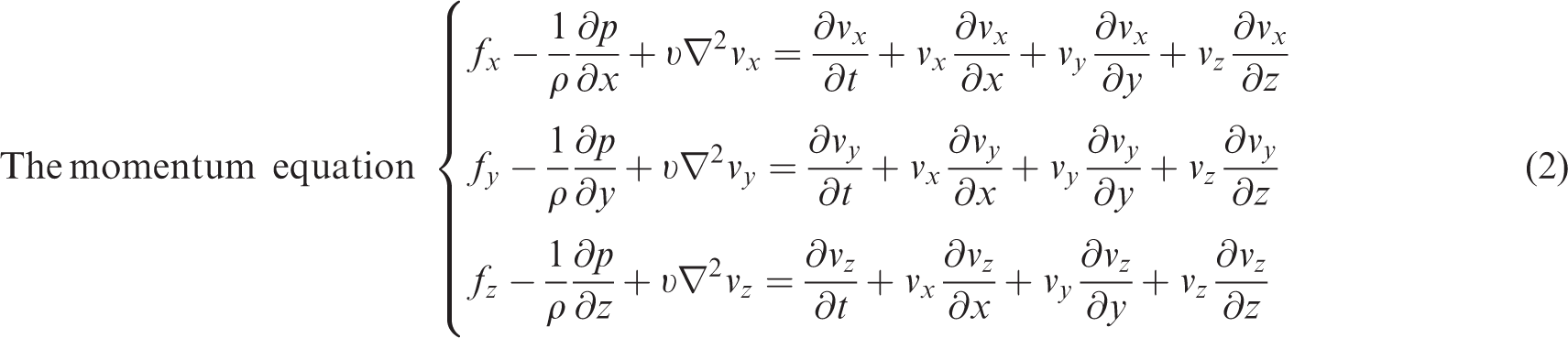
As the standard k–ε turbulence model is used widely in flow field, and especially, it is better in calculating the flow characteristics between reflux and axial flow. The chosen standard k–ε turbulence model is described as below.
The transport equation of turbulent kinetic energy k

The equation of turbulent dissipation rate ε

Purifying and silencing device model
Basic structure and dimensions
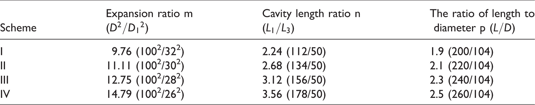
The structure of the developed exhaust purifying muffler is shown in Figure 1, including cavity (the inlet silencing cavity V1, the purifying silencing cavity V2, the outlet silencing cavity V3), the inlet pipe 2, the outlet pipe 5, purifying material 4 (ceramic foam), connecting flange 7. Ceramic foam was used as the purifying material, and as the foam ceramic had porous structure characteristic, the study of flow field in the ceramic foam primarily concerned with macro flow, so the purifying material (ceramic foam) was considered to be porous media, the purifying silencing cavity V2 could also be considered to be porous media region. The specific sizes are shown in Table 1.
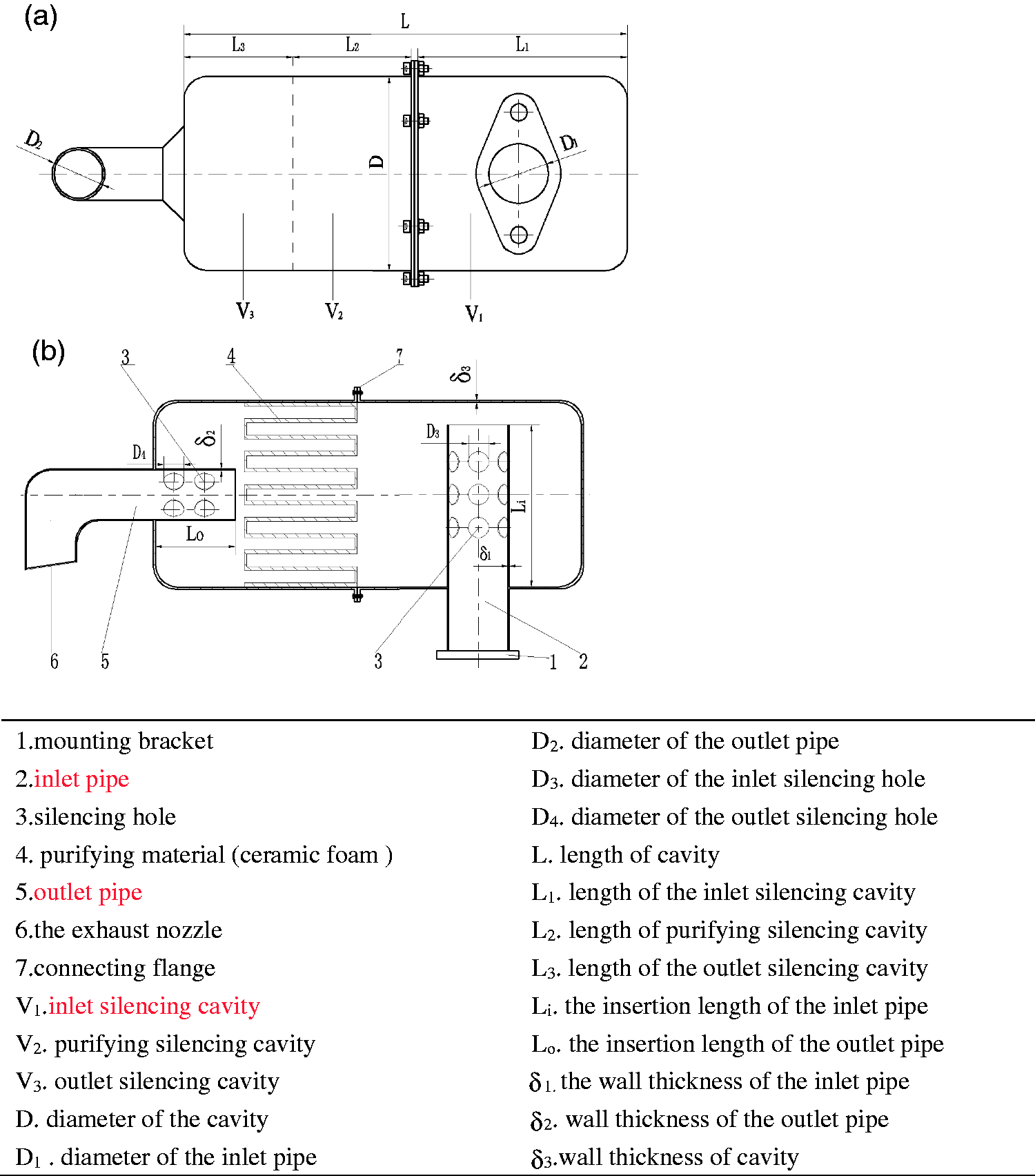
Schematic diagram of purifying and silencing device. (a) The main view of the device and (b) the profile view of the device.
The structure dimensions of the purifying and silencing device.
Mesh generation
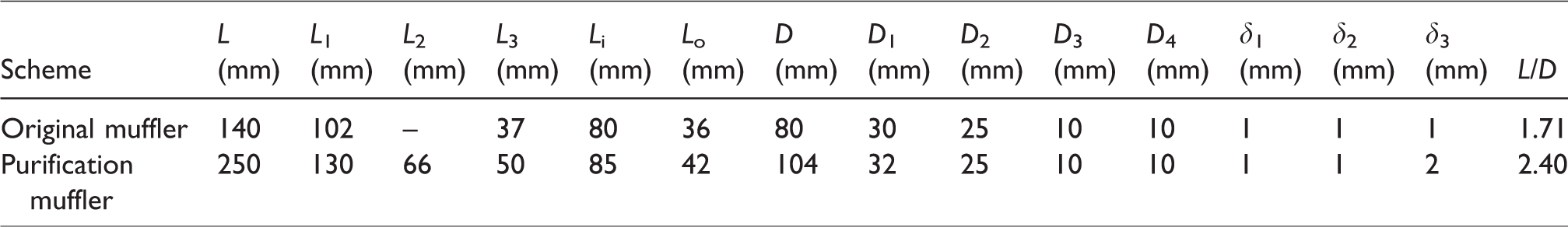
Because there are many structures of the purifying and silencing device and many silencing holes on inlet and outlet pipe and the shape of the purifying and silencing device is complex, simple structure or nonstructure grid does not apply to the model. So the purifying and silencing device is divided by the hybrid meshes. The grid size of each part structure is determined according to the size of the specific model, and the grid type should be chosen according to the shape and the complexity of each structure. As the wall of the inlet pipe region and the outlet pipe region is thin, the 2.0 mm tetrahedral mesh is adopted. As the size of the perforated structure area is small, the 0.8 mm tetrahedral mesh is used.
As the porous medium region shape and model size are large, the 3.0 mm hexahedral grid is adopted; the rest zone of the muffler is divided into two cavities by porous medium, and 4.0 mm hexahedral grid is used in these two cavities. After the mesh dividing, the views in X, Y dimension and silencing hole section are observed, respectively, as shown in Figure 2(a) to (c); the total number of grid units is 1,231,593, the total number of nodes is 211,246, and the total number of grid units at the porous medium is 3959.
Grid diagram of the purifying and silencing device. (a) Grid view in X dimension, (b) grid view in Y dimension, and (c) grid view at silencing holes.
Study on the flow field characteristics
Initial boundary condition
In the process of calculating the flow field by the finite volume method, 22 the following assumptions were made for the analysis model: (1) the influence of fillet and flange structure on the analysis results was out of consideration and (2) the value of the entrance velocity was uniform.
According to the structure characteristics of purifying and silencing device model, initial boundary condition was defined as the entrance of velocity, with the measured exhaust flowing velocity V = 30 m/s under the normal working load conditions of the diesel engine 2000 r/min and the condition of 50% load as the initial value.
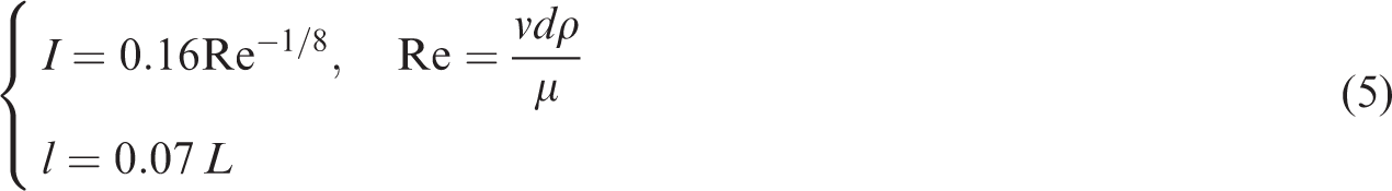
At the export of pressure, the relative reference pressure was 0 Pa; the wall surface was defined to be fixed and nonslip. The turbulence intensity I and turbulence scale l of the entrance and export could be calculated using formula (5), 23 and the calculation results of turbulence intensity I were 4.01 and 4.14%, turbulence scale l were 2.24 and 1.75 mm, respectively.
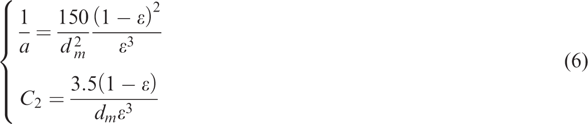
The permeability and inertia coefficient of fluid flow characteristics in porous medium were calculated by means of empirical formula (6);24,25 the second-order upwind discrete scheme and the SIMPLE method were used to calculate the flow field characteristics
In this paper, the hydraulic diameter of the inlet and outlet circular pipe is equal to the diameter of the pipe; the hydraulic diameters of the inlet and outlet circular pipe are 32 and 25 mm
Analysis of the flow field characteristics
According to the analysis of the velocity distribution regularities of velocity flow field and velocity vectors inside the purification muffler, the internal velocity mutation region can be known and the maximum speed region can be obtained. 26
Based on these, the velocity value in speed field of purifying and silencing device and distribution of velocity vector can be analyzed. Therefore, the X and Y sections of the model were chosen, which were convenient for the analysis of velocity distribution diagram and velocity vector diagram shown, respectively, in Figure 3.
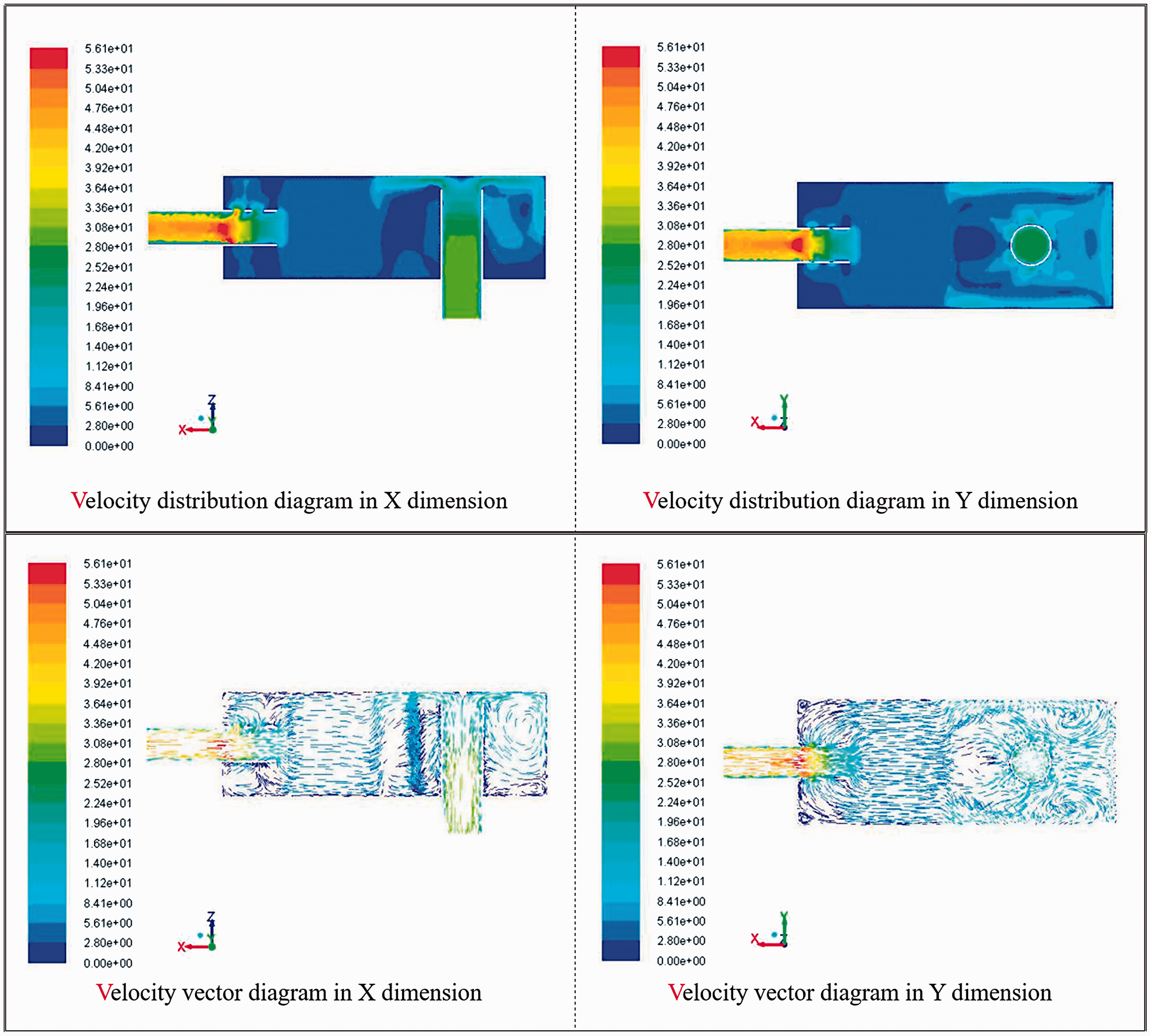
Velocity nephogram.
As shown in Figure 3, velocity in the inlet pipe, outlet pipe, and the cavity presented a certain regional distribution; turbulence was produced due to the high flow velocity in the inlet pipe and inlet silencing cavity. The velocity was the lowest in the porous media region, and the velocity was stable and the average was about 5 m/s, proving good speed-reducing effect. In the outlet pipe and outlet silencing cavity region, the air velocity was small near porous medium and the turbulence phenomenon was not serious, but the airflow gathered at the outlet pipe holes after flowing through the porous medium, with an obviously increasing speed. Specifically, the exhaust flowed into the inlet pipe at the initial speed of 30 m/s, and the airflow was blocked by the wall because of the side insertion of inlet pipe, where there was a great speed change, the difference of which was up to more than 15 m/s. At the same time, strong turbulence was produced, and the turbulence area in the right side of the inlet pipe was larger than that in the left side. Airflow spread out due to the sudden increase of the flow area after flowing through the inlet pipe to inlet silencing cavity, and the speed was reduced. The flow was relatively stable and the average flow velocity was maintained at about 16 m/s. When the air flowed through the porous media region, the flow velocity was stable and the velocity was further reduced, the average of which was 4–8 m/s, and the minimum velocity was also generated in the region. When the airflow reached the outlet pipe, the flow area became smaller, and because of silencing holes, the airflow began to converge, the speed gradually increased to about 28 m/s. After flowing through the outlet silencing holes, mass air began aggregating, and speed was further increased, reaching the maximum 53.1 m/s in the central axis.
There is a close relationship between the pressure loss value and the exhaust back pressure. Too much pressure loss will cause the increase of exhaust back pressure, 27 resulting in excessive exhaust resistance, and ultimately affecting the fuel economy, dynamic, and emission performance of the diesel engine. Therefore, through the analysis of the flow field pressure nephogram of purifying and silencing device, pressure distribution and variation inside the cavity could be obtained, and the structure zone and causes of the maximum pressure were analyzed in detail, and the corresponding pressure loss was calculated. Similarly, the X and Y dimensions of the pressure nephogram of the model were captured for analysis, as shown in Figure 4.
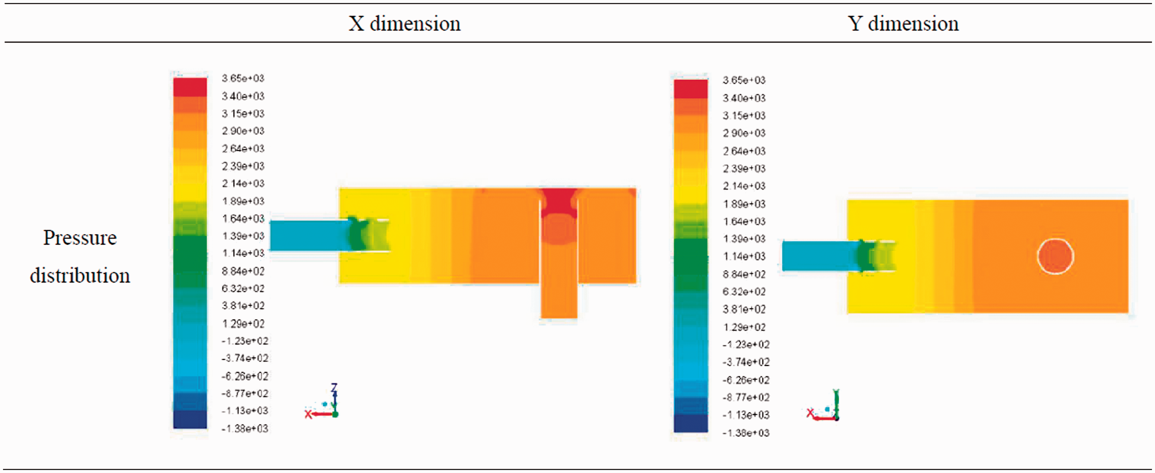
Pressure nephogram.
As can be seen in Figure 4, pressure nephogram appeared as regular distribution, respectively, in inlet pipe, inlet silencing cavity, porous medium, outlet silencing cavity, and outlet pipe. The direct impact of airflow and the cavity wall in the inlet pipe caused the direction change and speed reduction. The pressure increased significantly, the highest value reaching 3650 Pa. At the same time, the pressure changing value also reached the maximum about 650 Pa. There were two pressure values in the porous media region, and the pressure difference between the front and rear ends was about 400 Pa. After air flowing through the porous medium, the pressure in the outlet silencing cavity would be further reduced and the pressure of the region was about 2100 Pa.
The pressure in outlet pipe was further reduced to the minimum value. Because the speed of airflow aggregation increased sharply and the airflow sprayed at high speed from the outlet pipe, some current flows back, resulting in negative pressure, the value of which was about −123 Pa. The calculation result of the pressure loss was 3315 Pa.
Based on the analysis, it can be known that:
Due to the short distance between the porous medium and the outlet pipe, the time of the air flowing through is less, the number of cross-section variation and the change of airflow velocity are large, and the airflow affects the airflow impact with different airflow velocities; at the same time, the velocity will increase sharply due to the smaller section and airflow aggregation at the exit. Because there is a very close relationship between the airflow regeneration noise and airflow velocity, it is necessary to choose appropriate length of porous medium, to avoid the changes of direction and velocity of airflow within a short distance and avoid the strong collision, local high velocity region, and turbulent region caused by the unreasonable structure design. It can also be considered to partition design the function of each chamber to achieve smooth flow and improve the uniformity of the flow field. When the exhaust flows through the internal cavity of muffler, the pressure nephogram indicates that the pressure in the muffler has a obvious and regular fluctuation. The value and direction of velocity change sharply due to the accelerated fluid friction and collision caused by the turbulence, which causes local energy loss and dissipation and results in pressure loss. At porous medium, the pore structure and the sectional mutation area, the velocity distribution of the section is also changing, while the gas contracts, causing rapid and large air pressure changes, and large pressure loss. The calculation result of the pressure loss of purification muffler is 3315 Pa, which is 2% higher than that of the original muffler. The pressure loss is not significantly increased and will not cause large exhaust back pressure, which has a significant impact on the fuel economy and dynamic performance of diesel engine. Porous medium of the purification muffler has great influence on the velocity and pressure distribution of the internal flow field. For the length and location arrangements of the porous medium, the change rate of velocity and pressure fluctuation need to be considered, which is conducive to the formation of uniform flow field and pressure loss reduction.
Flow field study based on structure factor
Scheme design based on structure factor
It can be known from the analysis of the flow field of purification muffler that the porous medium has great influence on velocity and pressure distribution of the flow field. Combining the analysis data and design principles, porous media parameters not changing in scheme design can avoid the increase of uncertain factors. In this paper, three typical structure factors of purification muffler were selected, the expansion ratio (
Structure factor parameter table.
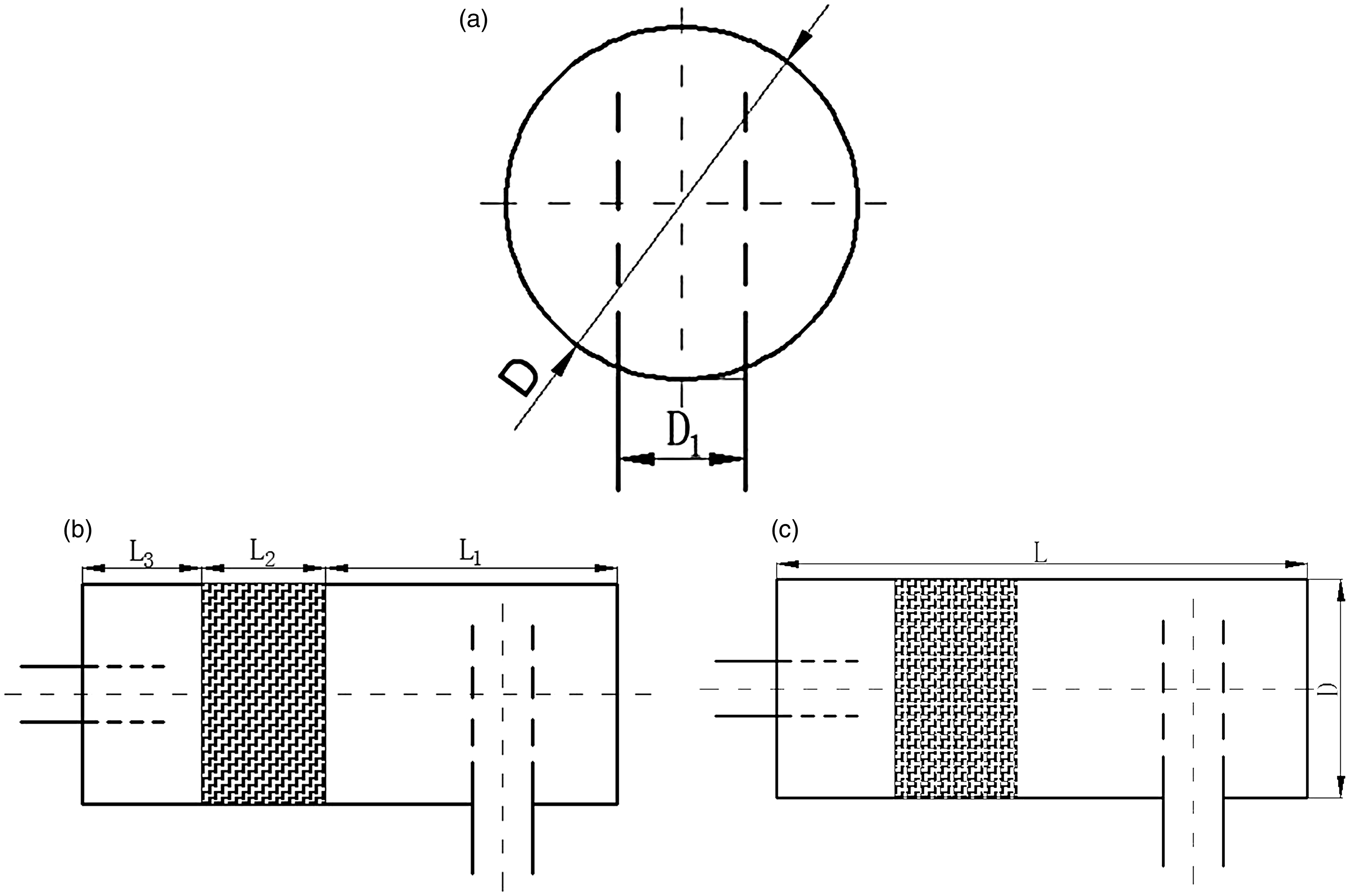
Schematic diagram of each structure factor. (a) Expansion ratio, (b) cavity length ratio, and (c) the ratio of length to diameter.
Analysis of the flow field characteristics
The X and Y dimensions of the nephogram of the model were captured for analysis. Considering the respective analysis of flow field change of structure factors, the Z dimension of a section was captured, as shown from Figures 6 to 11.
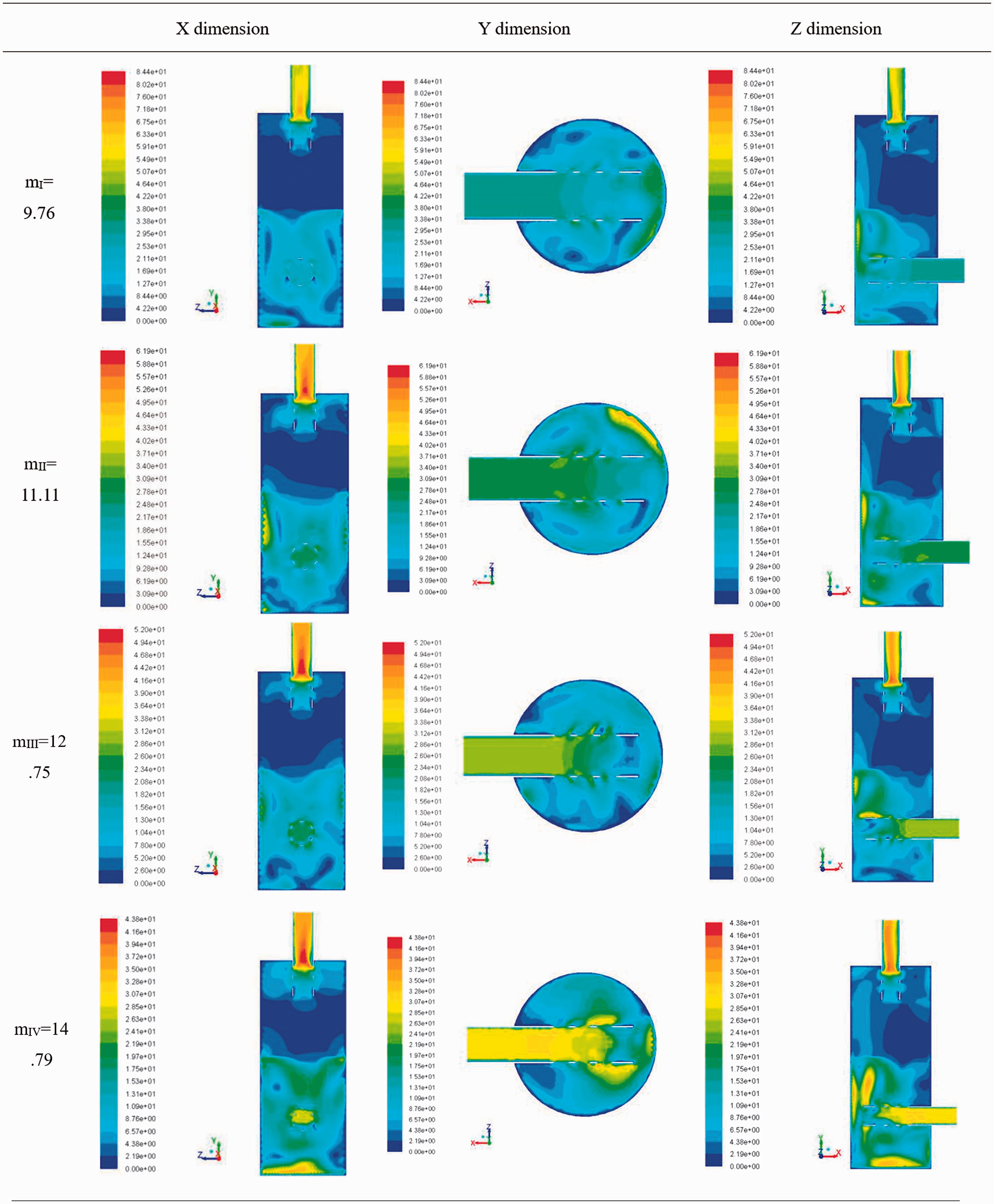
Velocity nephogram.
From the X dimension of the nephogram in Figure 6, we can see that when the air gathers after flowing through the silencing holes of the outlet pipe, the velocities of the expansion ratio schemes achieve the maximum at the exit, and with the increase of the expansion ratio the corresponding maximum speed gradually decreases. When mI = 9.76, the velocity is 84.4 m/s, and when mIV = 14.79 it is 43.8 m/s, indicating the great change of the speed. The velocity variation of the exit of the outlet pipe is more complicated than that of the entrance of the inlet pipe. At the same time, in each expansion ratio scheme, the low velocity region of the exhaust purification muffler is the porous medium region, and it is about 2–5 m/s. From the Y dimension in Figure 6, we can see that after the exhaust gas passing through the inlet pipe, the airflow is shunted by the silencing holes on the inlet pipe and there is a certain amount of approximately 5–8 m/s decrease of the flow velocity. When the airflow reaches the wall in the entering direction, there is a certain amount of increase of the velocity due to the impact caused by side inserted inlet pipe. From further analysis of Z dimension in Figure 6, it can be seen that after air flowing into the inlet silencing cavity, low velocity region where the value about 15–20 m/s is produced by the increase of flow area, and a certain degree of turbulence appears due to the velocity change. With the change of the expansion ratio, the flow area is different after flowing into the inlet pipe, and different velocity regions are generated in the inlet pipe. When the mIV = 14.79, the velocity variation is large and the turbulence region increases. Therefore, the velocity variation is generated when the air flows through the flow area mutation region of the inlet and outlet pipe, and turbulence is easy to generate in the region. The interference and reflection of the airflow and sound wave can be caused by the mutation section, weakening the acoustic energy. 28
From the X, Y dimension of the pressure nephogram in Figure 7, it can be known that because of the side inserted inlet pipe, the impact of high-speed airflow to the internal wall of muffler leads to the velocity mutation and the pressure reaches the maximum in the inlet pipe. With the increase of the expansion ratio, the maximum pressure of each scheme decreases gradually; when mI = 9.76, the maximum pressure is 4750 Pa and when mIV = 14.79, it is about 1830 Pa. The flow is stable and the pressure fluctuation is small as the flow velocity is low at the porous medium. Based on the further analysis of Z dimension in Figure 7, the pressure shows constant order ladder distribution, and there is pressure fluctuation in the inlet and outlet silencing hole areas. With the increase of the expansion ratio, the airflow expansion area of the inlet pipe and inlet silencing cavity decreases, where the local pressure fluctuation range and change value are relatively large. The airflow expansion area of the outlet silencing cavity has no change, so the local pressure fluctuation is small. With the change of expansion ratio there is a certain link between the pressure difference and expansion ratio changes of each scheme. When the changing value of the expansion ratio of the two schemes is large, the pressure value change is also large; otherwise the pressure difference is small, which is mainly caused by changes of flow area. It can be seen that the local pressure fluctuations are prone to occur in the porous structure and mutated cross-section, and the calculated pressure losses of each scheme are, respectively, 2826, 2269, 2027, 1948 Pa. The pressure loss varies greatly among different schemes.
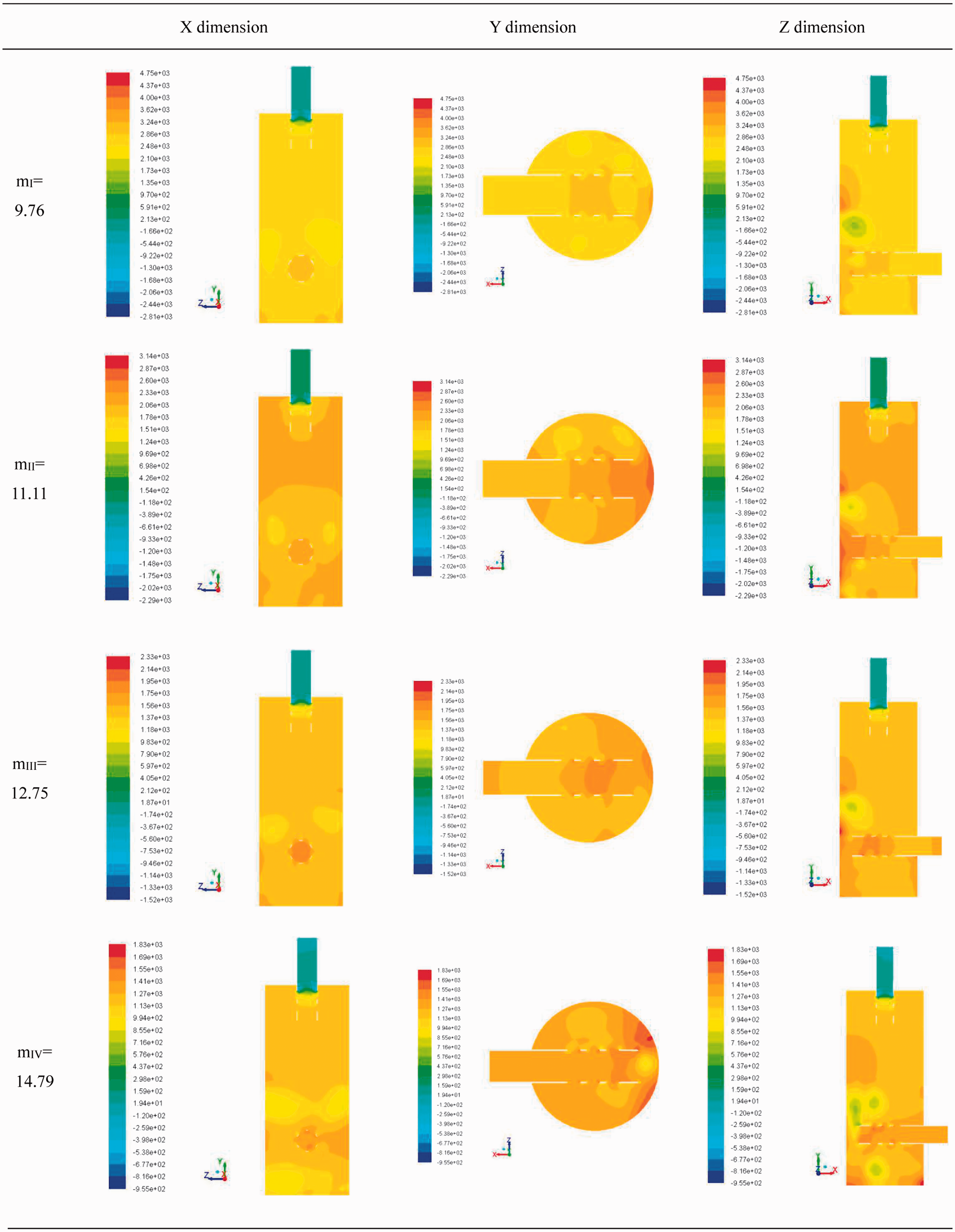
Pressure nephogram.
It can be analyzed that the change of expansion ratio has certain effect on the flow field distribution of muffler; expansion ratio changes can cause cross-sectional area changes when the air flows through the inlet pipe into the inlet silencing cavity, which causes the changes of velocity and pressure fluctuation, influencing the pressure loss of the overall flow field greatly.
2. Based on the analysis of X dimension velocity nephogram in Figure 8, the speed of schemes with different cavity length ratio reached the maximum in outlet pipe, and it can reach 101 m/s when nII=2.68, which indicates that the maximum velocity of the schemes changes greatly, and the speed change of the exit is more complex than that of the entrance. The flow velocity in porous media is low, and with the change of the length of porous medium, the area of low velocity region also changes. It can be learned from the Y dimension in Figure 8 that the color of the nephogram in the silencing hole parts of the inlet pipe changes obviously, which indicates that there is large velocity change in these structures and turbulence due to the section mutation after the air flows through. With the increase of cavity length ratio, the airflow change in the inlet pipe of the schemes is not obvious. The velocity change is small between schemes with different cavity ratio, and the speed remains 30–35 m/s.
Based on the analysis of Z dimension nephogram in Figure 8, it can be seen that the silencing holes of the inlet pipe have good airflow shunt and speed reduction effect, and the turbulence in the inlet pipe is not obvious. The overall velocity change in the inlet silencing cavity is not large, approximately 5–8 m/s. The small range regions with high speed are generated in the inlet pipe and the opposite wall surface and are more obvious when nII = 2.68.
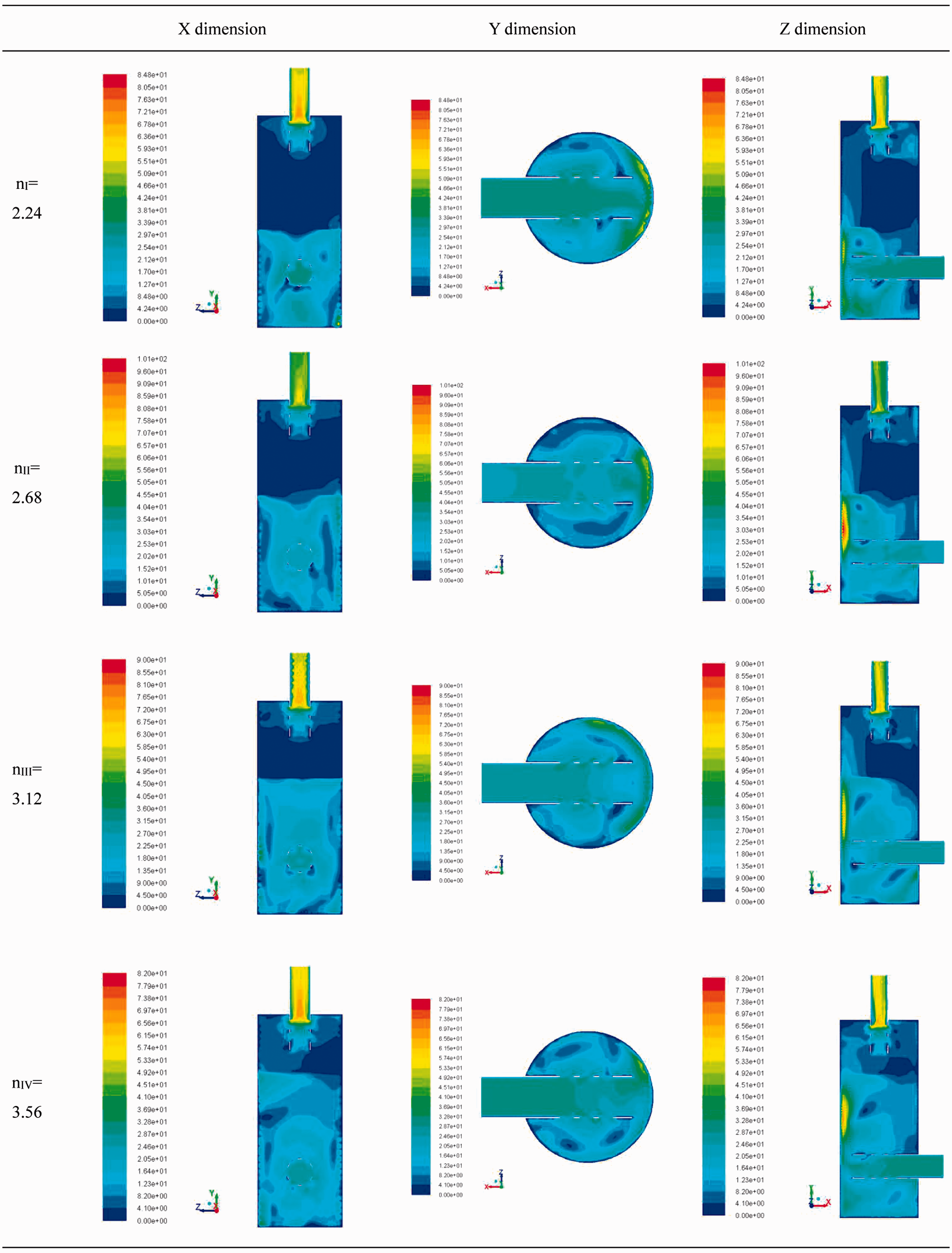
Velocity nephogram.
It can be seen from X, Y dimension nephograms in Figure 9 that the pressure distribution is consistent with trapezoidal distribution and is local uneven in the inlet pipe and outlet pipe. The pressure values in the same section are varied. Especially when the air flows through the inlet pipe to the inlet silencing cavity, amplitude and range of pressure fluctuation are large. Based on the analysis of Z dimension in Figure 9, due to the unchanged length of outlet silencing cavity and the change of porous medium length, the airflow area changes mainly in the part of the inlet silencing cavity, thus the local pressure fluctuation is mainly produced in the inlet silencing cavity. The maximum pressure is also generated in the inlet pipe. With the increasing of cavity length ratio, the maximum pressure generating region transfers, and when nIII = 3.12 the maximum pressure is 4160 Pa at the front end of porous media. The porous medium length decreases, then the length and the volume of the inlet silencing chamber increase. The flow space becomes larger when air enters the cavity, and the increasing distance between the wall and airflow makes the air shunt, decreasing the speed. When nIV = 3.56, the flow region is the largest, the velocity and the pressure change are the least, and the calculated pressure losses corresponding to each scheme are 2632, 2893, 2665, 2565 Pa, respectively. The change of pressure loss is not large.
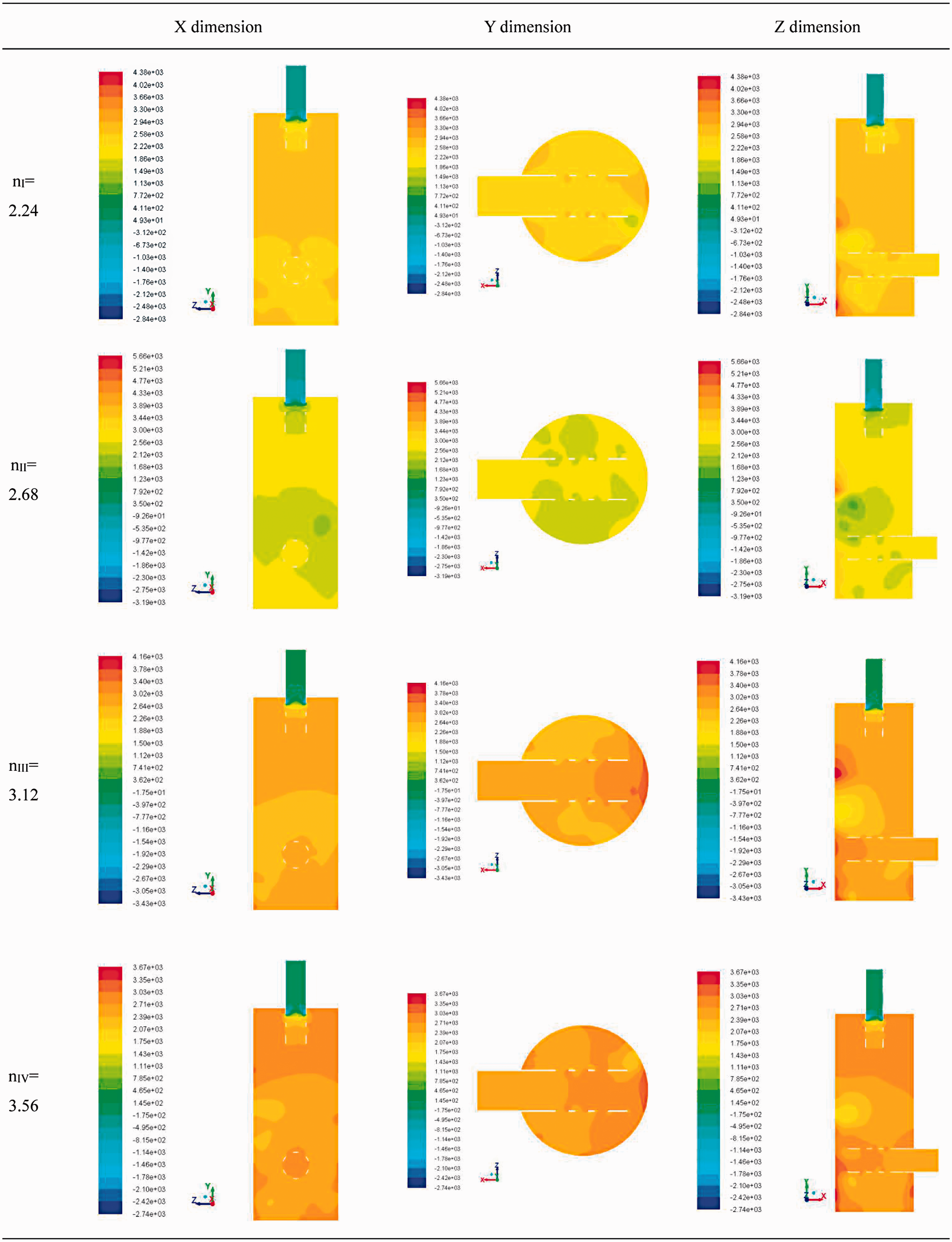
Pressure nephogram.
Velocity nephogram.
Based on the above analysis, the change of porous medium length can cause the change of airflow space in the inlet silencing cavity, and the velocity and pressure in the cavity change greatly. The change of pressure loss of the schemes of cavity length ratio is less compared to the schemes of the expansion ratio.
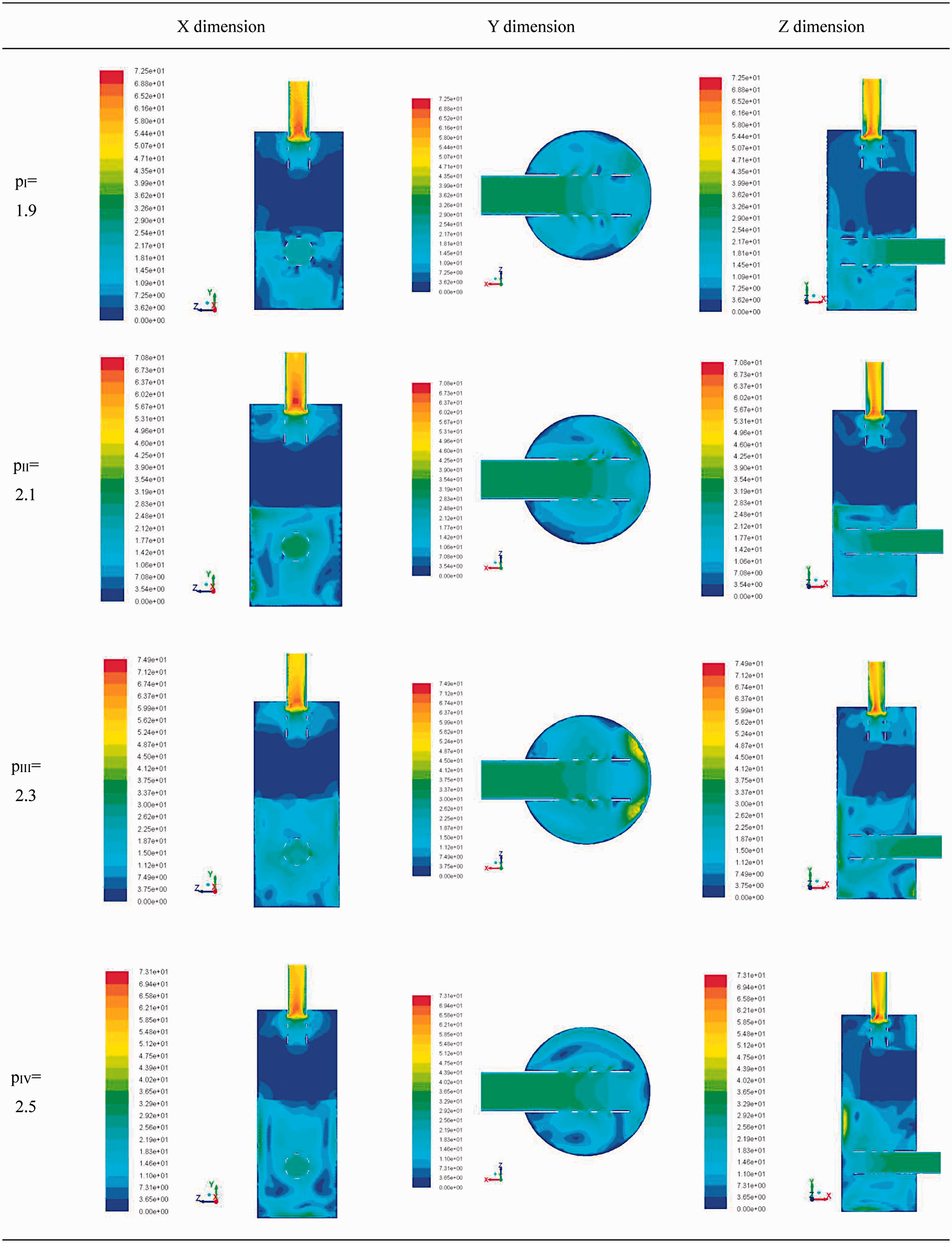
3. It can be known from the analysis of X dimension nephogram in Figure 10 that the velocity of the schemes of the ratio of length to diameter in the outlet pipe reaches the maximum, about 70 m/s, and the difference is not large. At the same time, with the increase of the ratio of length to diameter, the flow space in the inlet silencing cavity becomes larger, conducive to the smooth flow of air flow. Low velocity area is in the porous media region, and the velocity is about 3.5–7.5 m/s. Based on the analysis of Y dimension nephogram in Figure 10, with the increase of the ratio of length to diameter, airflow velocity has little change in the inlet pipe, and when pIII = 2.3, the speed of local airflow generates on the positive wall is 53.4 m/s. From Z dimension nephogram in Figure 10, we can know that there is an obvious speed changing region in porous medium. When pI = 1.9, the distance between the inlet pipe and the porous medium and the flow distance in the inlet silencing cavity are short, leading to velocity mutation within a short period of time, and the speed interface is not obvious. With the increase of the ratio of length to diameter, the flow distance increased, the speed interface becomes relatively obvious, but when pIV = 2.5, the airflow in the region is disorder and prone to generate local high velocity area, resulting in a small range of turbulence.
Based on the analysis of X and Y dimension nephograms in Figure 11, the pressure nephogram presents a good overall regular distribution. The change of airflow velocity in section break and porous structure is prone to cause the pressure fluctuation. High pressure is generated in the vertical region of the inlet pipe and inlet silencing cavity, and when pII = 2.1, the pressure reaches the maximum pressure about 4080 Pa. There are two obvious pressure distributions in the internal inlet pipe, and the pressure and the regional range change little with the change of the ratio of length to diameter. From the Z dimension nephogram in Figure 11, the pressure fluctuations are produced in the inlet pipe and outlet pipe and the inlet silencing cavity. With the increase of the ratio of length to diameter, the volume of the inlet silencing cavity and the internal airflow space become larger. The pressure amplitude changing value in the inlet silencing cavity is smaller, and when pIV = 2.5, the pressure change in the chamber is about 500 Pa. The calculated pressure losses of the schemes of the ratio of length to diameter are 2732, 2821, 2750, 2739 Pa, respectively.
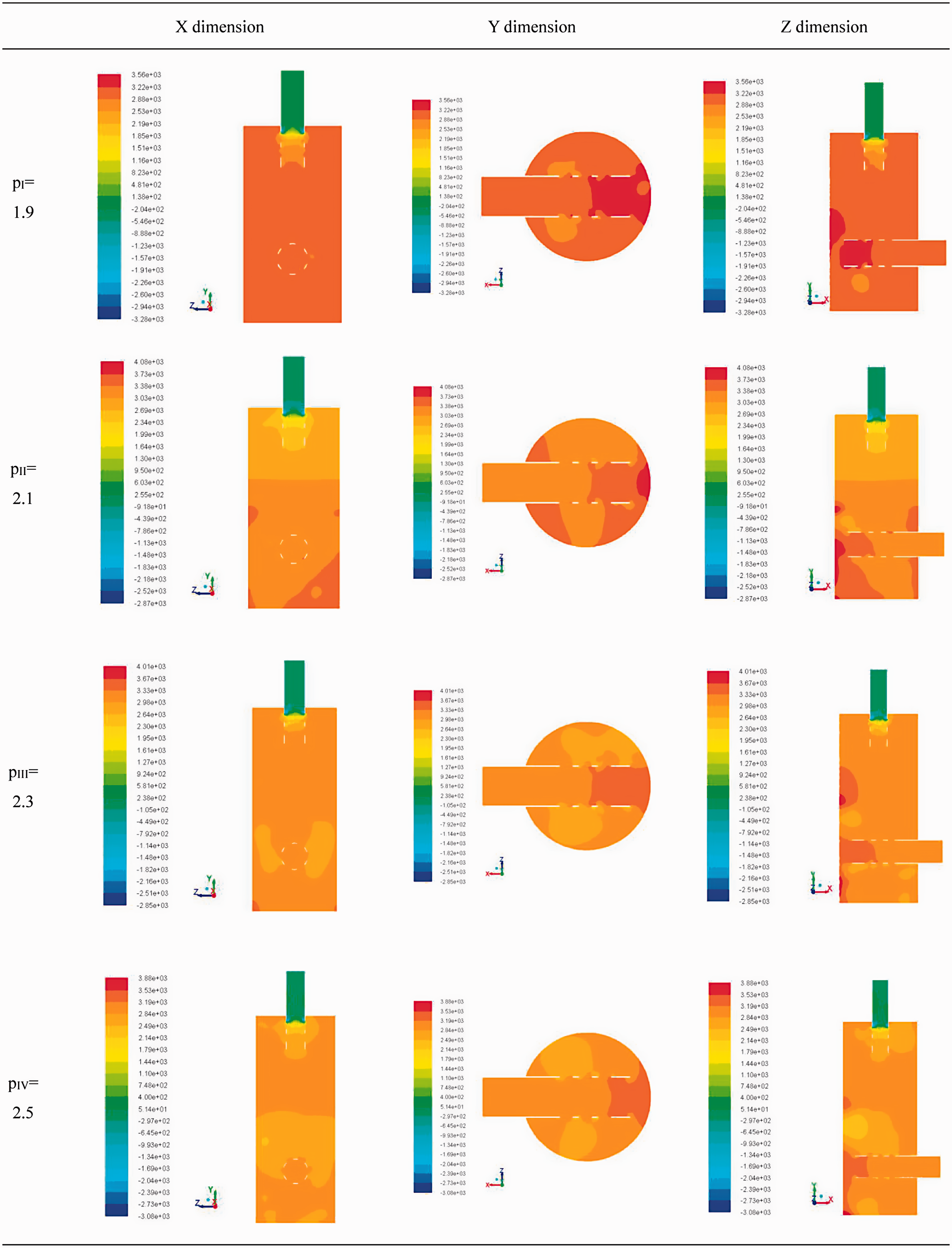
Pressure nephogram.
Based on the analysis, with the increase of the ratio of length to diameter, the volume of inlet silencing cavity and the airflow space are larger. The flow velocity is stable and the change is small, the pressure change in the cavity is also small. The pressure loss change of the expansion ratio schemes is larger when compared to the schemes of the ratio of length to diameter.
Conclusions
This paper studies on the flow field characteristics of a novel diesel engine exhaust purification muffler and discusses the effect of the flow field when the structure of the exhaust purification muffler factor parameters changes; the conclusions are as follows:
The porous medium has great effect on the velocity and pressure distribution of the internal flow field. Reasonable arrangements for the location and length can make flow velocity steady, distribution uniform, and the velocity changes small when the air flows through the porous media region, providing a good pressure reduction and deceleration effect. The results show that the pressure loss of the purification muffler is 3315 Pa, which is 2% higher than that of the original muffler. The pressure loss has not been significantly increased and will not produce a larger exhaust back pressure. The inlet pipe and outlet pipe and the silencing hole (the mutation section) can cause mutations in flow velocity and direction vector, prone to generate pressure fluctuations and turbulence. The velocity change in the exit of the outlet pipe is complex compared to that in the entrance of the inlet pipe. At a given initial velocity, low velocity region appears in porous medium in the schemes of the structure factors. With the increase of the expansion ratio, the inlet pipe diameter decreases, which can cause the airflow cross-section area to change due to air entering into the inlet silencing cavity. The generated speed change and pressure fluctuation has great influence on the velocity field and the pressure loss. With the increase of cavity length ratio, the flowing distance in the inlet silencing increases, and the length of porous medium becomes small, which causes more local turbulence and pressure fluctuation. With the increase of the ratio of length to diameter, the volume of inlet silencing cavity and the air flow space increases. The flow velocity is stable and the change is small, and the cavity pressure change is also small. The change of the structural parameters of each scheme has a certain influence on the pressure loss. The pressure loss caused by the expansion ratio changes greatly, and the pressure loss changing value caused by the change of the cavity length ratio and the ratio of length to diameter is small.
Footnotes
Declaration of conflicting interests
The author(s) declared no potential conflicts of interest with respect to the research, authorship, and/or publication of this article.
Funding
The author(s) disclosed receipt of the following financial support for the research, authorship, and/or publication of this article: This work was financially supported by the National Natural Science Foundation Key Project of China (No. 91541121), Scientific Research Fund of Hunan Provincial Education Department (No. 16B235), Hunan Provincial Innovation Foundation For Postgraduate (No. CX2016B686), and Shaoyang University Innovation Foundation For Postgraduate (No. CX2016SY016).