
Abstract
Today, die design standards are used to design the structure of die components. These standards are usually based on high safety factors. So, the die components are often heavier and larger than required. In this article, a software package is developed which can design an appropriate topology of body structure of stamping die components with a reduced weight. This is done by implementing the evolutionary structural optimization algorithm. The proposed structure can also be modified by the designer to accommodate for a simpler casting method. This software package is developed in Microsoft Visual C# programming environment with a link to Abaqus software to analyze the finite element simulation of the process. The operation of the software is demonstrated by an example where the die for a sheet metal part is studied. The die components are initially designed, analyzed and compared with the standard die (the die which is in general use today). The final results show a reduction of 37% of volume and 8% of maximum displacement, respectively.
Keywords
Introduction
In the usual stamping die structure layout, uniformly distributed ribs are designed for supporting the die face. The die structure is designed in accordance with the rules used by the experts and the existing standards. However, in some cases, the pressure distribution of the die face is ignored by the designer. 1 This design thus leads to the increase in the size and weight of the stamping die which results in excessive costs as well as difficulties in transportation and installation. 2 On the other hand, design of a die with fewer structural ribs can save the cost of material and energy consumption in operation and transportation but may have the problem of die failure. Consequently, the light-weight design of the large-scaled stamping die with structural optimization methods is important.
In the last two decades, the technique of topology optimization has been applied to generate a reasonable structural configuration by redistributing the material in the design domain with the prescribed loads and boundary conditions. In the final design, a light-weight structure is obtained with the structural stiffness, strength and some other satisfied performances. 3 Generally, the distribution of the material is described with a number of different methods. Till now, considerable research and various topology optimization methods such as homogenization methods,4–8 solid isotropic material with penalization (SIMP) methods,3–4 level set methods (LSM)9–11 and evolutionary structural optimization (ESO) methods12–15 are proposed. Among these methods, the ESO method is more popular and used widely in both the academia and the engineering applications optimization. 16
Currently, most of the existing research works on sheet metal forming are concentrated on numerical simulation of different kinds of forming processes to improve the precision of produced parts. 17 For example, Yan and Klappka 18 studied the spring-back behavior of panel forming using multi-point stretch forming (MPSF) technique. They specified that numerical simulations indicated that the spring-back (SB) effect is loading-path dependent and may be linearly related to material properties in the case of simple geometry. However, the effect of sheet thickness and curvature may be less significant. An axisymmetric rubber-pad forming operation is investigated via numerical simulations and experiments by Ramezani et al. 19 Some key process parameters, such as rubber material, hardness of flexible punch, stamping velocity, rubber-pad thickness and friction are studied in detail. Good correlation is achieved between the finite element (FE) results and experimentally measured thickness–thinning in the formed part. Wang et al. 20 carried out a series of numerical simulations on MPSF processes where the shape error and non-uniformity in thickness distribution of the sheet metal part were analyzed. The results show the influences of the punch element size, the sheet metal thickness and the elastic cushion on the forming results. Farsi and Arezoo 21 studied the influence of the area of holes, die angles, die widths and punch radius on the value of the spring-back and the bending forces in V-shaped dies. It is found that all these parameters affect the spring-back and the bending forces. A new equation is suggested in this article to predict the bending forces in V-shaped dies for parts with holes on the bending surfaces. Fazli and Arezoo 22 presented an analytical method for estimating the limiting drawing ratio (LDR) of the redrawing stages in deep drawing process of axisymmetric components. In their method, the effects of parameters of die, punch and blank holder arcs are taken into account for the analytical determination of LDR. This method can predict the LDR for redrawing with/without intermediate annealing processes. Yi et al. 23 developed an analytical model based on differential strains after relief from the maximum bending stress for six different deformation patterns. They used each deformation pattern to estimate spring-back by the residual differential strains between outer and inner surfaces after elastic recovery.
Many researches have been carried out to improve the forming condition of sheet metal forming operations. However, there has been a small number of research work in die topology optimization, from which a few are the optimization of the structure of stretch forming and stamping dies. These are as follows.
Sheu and Yang 1 attempted to predict the pressure on the die face of stamping die by FE method. The inner structure is then designed by modifying the size and layout of the ribs with the size and shape optimization methods. The optimal results are completely different from the usual design, that is, a uniform distribution of the ribs. Nilsson and Birath 24 simulated the variation of the surface loads during the stamping process by means of time integration, where the process of lifting and stamping are taken into account. Topology optimization is then applied to save the weight by maintaining the structure rigidity and strength. Similarly, Xu et al. 25 developed the inner structure of the stamping die with the topology optimization method. Based on the platform of LS-Dyna and Hyperworks, 28% of the total weight is saved, where the topology optimization method is proved to be an effective light-weight design method. Zhu et al. 2 used Abaqus to simulate the procedure of skin stretch forming numerically. Then, topology optimization was carried out accordingly to maximize the structural stiffness with the material properties and the boundary conditions properly defined. Finally, the comparison of the numerical results and usual design shows that the topology design can improve the stiffness and strength of the stretch forming die significantly.
In spite of these researches found by the author in literature for topology optimization of stamping dies, still there is no effective and efficient method which can automatically optimize the topology of stamping dies according to prescribed loads and boundary conditions.
In this article, a software package based on topology optimization is presented. This software uses ESO method to reduce the volume of the main components of the stamping dies, including punch, die and blank holder while the die structure can bear the forces of sheet metal forming operation.
Topology optimization method
Topology optimization may significantly enhance the performance of structures for many engineering applications. It has been exhaustively studied and various methods have been developed over the past few decades. Among them, the ESO method is one of the most popular techniques for topology optimization. 26 The ESO method proposed by Xie and Steven12–14 and Xie and Huang 15 is based on the simple idea that by progressively removing inefficient material from a part, the topology of the remaining design will evolve toward an optimum structure. 27 The removal of the elements is controlled by a rejection criterion. This criterion typically compares a scalar functional of the mechanical responses of the elements with a threshold value. The elements with values less than the threshold will then be removed. The ESO procedure can totally remove the inefficient elements. 28
Evolutionary procedure
The stress value in any point of a part can be determined by implementing FE analysis. A good criterion of inefficient use of material is the low values of stress in some regions of the part. Ideally, the stress should be close to the safe and same level at every region of the part. This concept, based on the local stress level, leads to a rejection criterion, where the low-stressed material is considered to be under-use and removed. The removal of material can be done by deleting elements from the FE model. 26 In the original version of the ESO method, 12 the rejection criterion is based on the von Mises stress. The von Mises stress of each element is defined as equation (1)
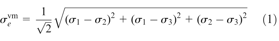
where σ
1, σ
2 and σ
3 are the principal stresses. The rejection ratio (RR) is defined as a ratio of von Mises stress of the eth element (
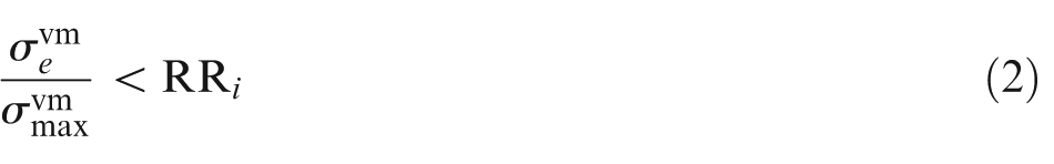
The elements that satisfy equation (2) are removed from the part. 27 After a small number of iterations, all elements will have stress levels higher than the threshold level, because the low stress level elements are removed. This stage is noted as steady state. The RR is increased by a pre-defined step size referred to as evolution rate (ER) after a steady state, 27 as shown in equation (3)
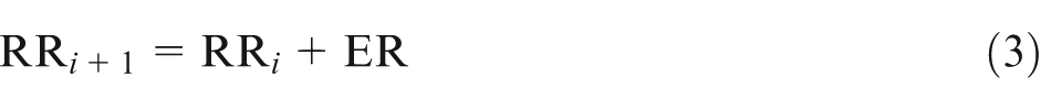
This procedure continues with the new RR to reach another steady state and then until attaining a desired optimum state. Figure 1 shows the logical steps that define the ESO method.
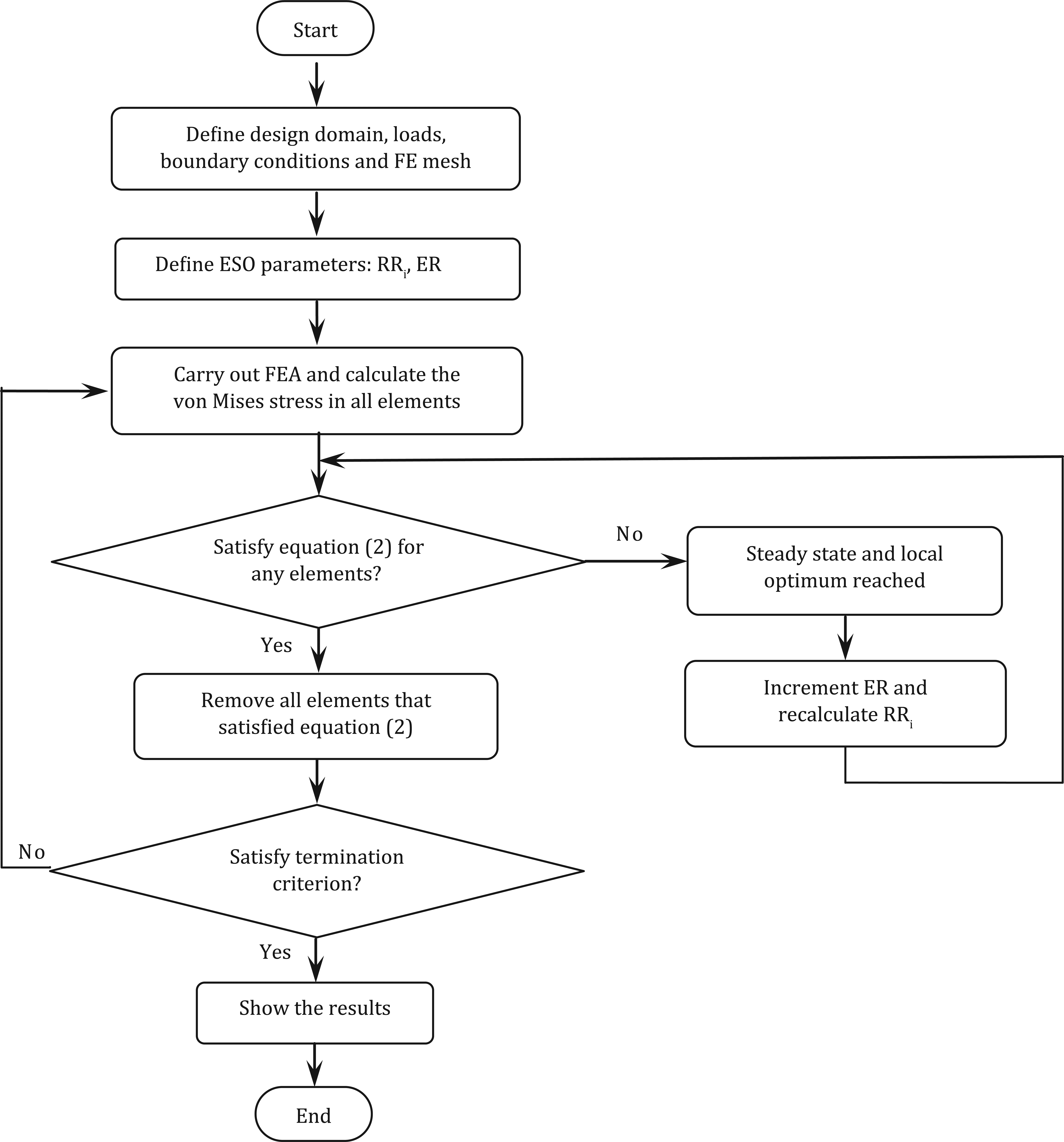
Flowchart of the ESO method.
Problem definition
The main components of stamping dies of large sheet metal parts, including punch, die and blank holder are large in weight and size. In most cases, forming forces applied to these components are not great enough to cause a considerable stress and strain. So, in order to overcome these forces, a complete solid part is not required. It means a significant part of these components can be made of holes and cavities. However, to achieve the optimal results, much attention should be paid to the design of these holes and cavities.
Today, die design standards are used to design the structure of die components. These standards are based on high safety factors due to high forces applied in the forming operations and not on a topology optimization algorithm. So traditionally, the die components are designed heavier and larger in volume than required. This in turn calls for higher prices of dies and transport and production energy required per part. Therefore, alternative methods to reduce the weight of the die components are required.
In this article, a software package which can design an appropriate topology of body structure of stamping dies with a minimum weight is presented. This software implements FE analysis using topology optimization algorithm to remove the excess solid volume from a die component to create a new lighter structure which resembles the sheet metal part shape and applied forces in the operation. Finally, the proposed structure could also be modified by the designer to accommodate for a simpler casting method.
Design of die components based on standards
Using the die design standards usually leads to dies with regular shape and structure. These standards usually recommend rectangular walls (ribs) to support the die face as shown in Figure 2. The range of distances between ribs is defined as a multiple of the rib thickness. The standard defines a minimum value for rib thickness according to the manufacturing limitations. This method is completely independent of the shape of sheet metal part and the force applied in forming operation. This usually leads to an overdesign and a non-uniform safety factor in different points of the die. In addition, the experience of designer plays a very important role on the final topology of the die, which causes different die designs for the same cases. For example, in Figure 2 that represents a back view of a typical die component, the rib thickness and the distance between them in Iran Khodro Company (IKCO) design standard 29 are shown:
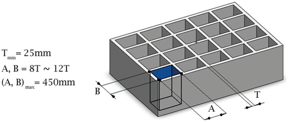
Rib thickness and distances between them in back view of a die component, 29 where T, A and B are the rib thickness, the longitudinal distance and the transverse distance between two ribs, respectively.
The height and angles of internal ribs are constrained in these standards. For example, these limitations in the IKCO design standards are expressed and illustrated in Figure 3:
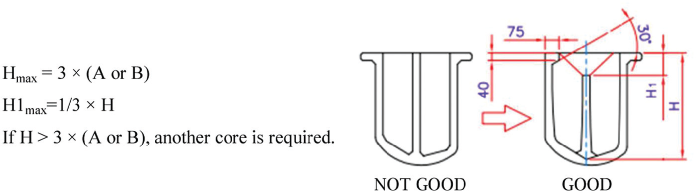
Limitations of height and angles of internal ribs in IKCO design standards. 29
In addition, some other guidelines are defined in the same standards as shown in Figure 4.
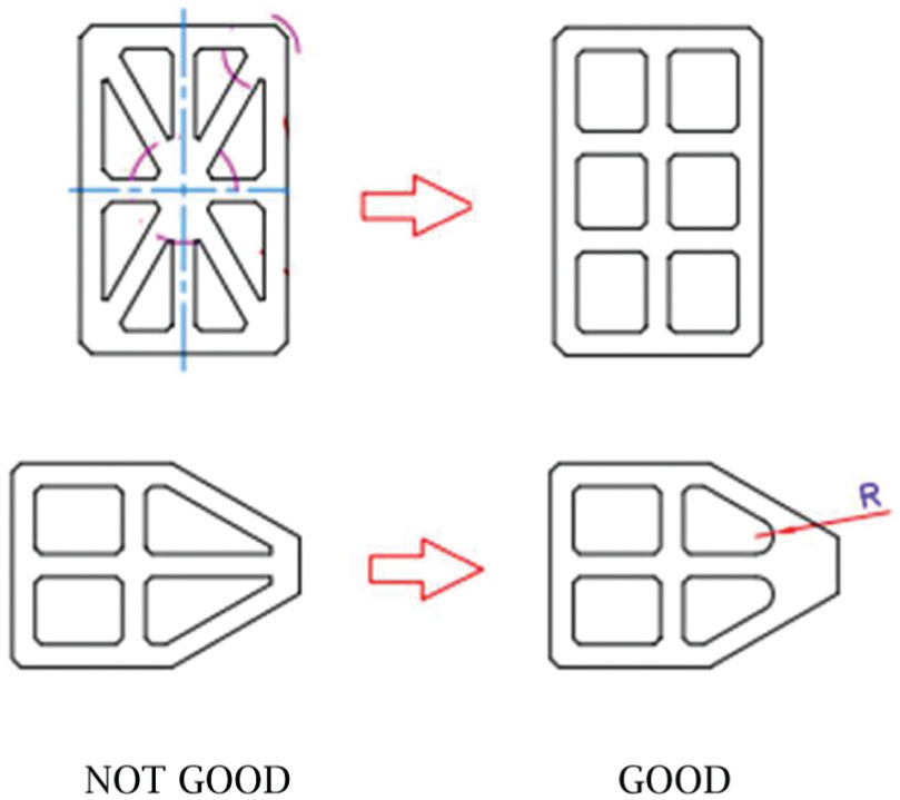
Design guidelines for die components in IKCO design standards. 29
Optimal design algorithm of die body
The software package in this work is developed in Microsoft Visual C# programming environment and is connected to Abaqus software to carry out the FE simulation process. The designer creates three-dimensional (3D) solid model of the die components and a surface model of a blank in computer-aided design (CAD) software. These are the input to the FE software. In most sheet metal forming analysis, die components including punch, die and blank holder are modeled as rigid parts. However, in this research, these are modeled as solid and deformable parts to implement the optimization algorithm regarding their volumes. Next, boundary conditions, loads, FE mesh, and design and non-design space are defined by the designer.
According to the restrictions of the problem, the volume of solid components requires to be divided into a non-design and a design space (Figure 5). Since the objective is finding the distribution of optimal material without changing the current design of the part, the material in contact with the blank is set as a non-design space. It means, during the topology optimization, no material should be removed from non-design space. In addition, the outer shape of the die is also set as non-design space so the same press can be used in stamping operations. The entire volume below the non-design space is set as available design space to allow the topology optimization to find the optimal material distribution. The design and non-design spaces are shown in Figure 5(a) and (b) in the upper and reverse view of the die part, respectively.
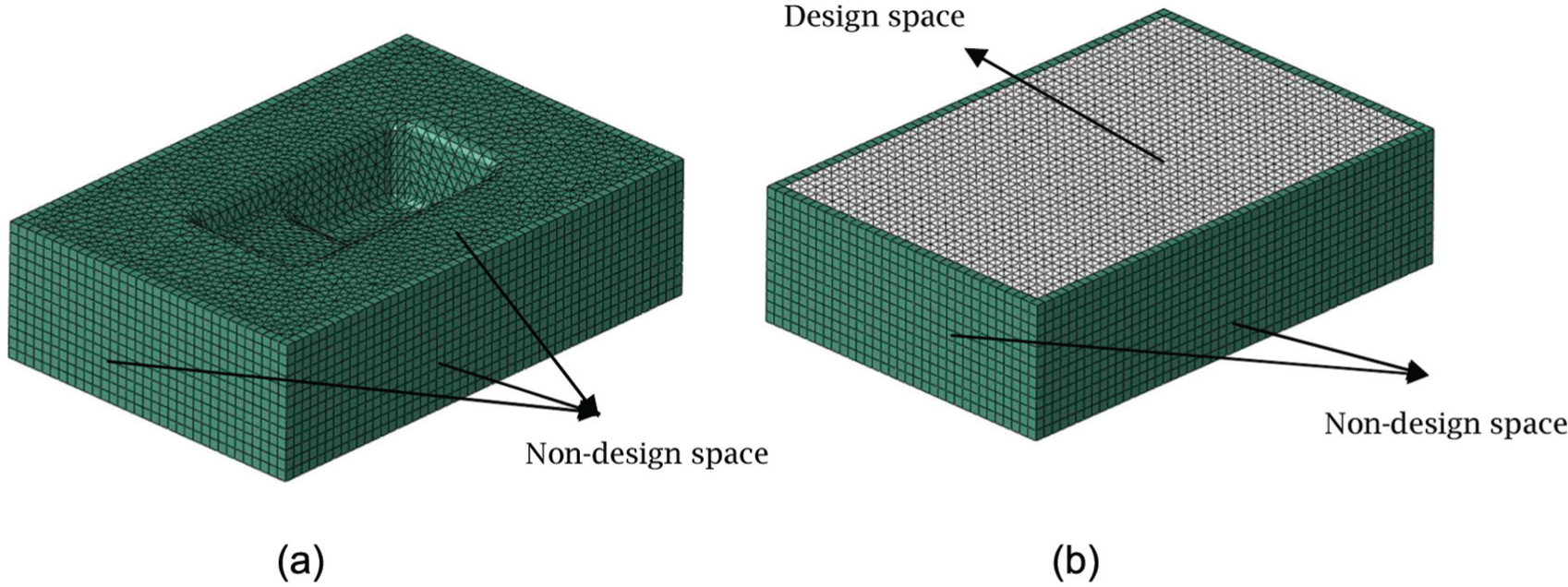
Design and non-design space of the die part in (a) upper view and (b) reverse view.
After defining the parameters of simulation, the input file of software package is created by the designer. The software package is capable of analyzing the sheet metal forming operations and generating results automatically. In the next step, the obtained results are extracted by python script from output file of FE software. This script opens this file and extracts the stress of each element and displacement of each node of the die components and saves them in a pre-defined format in a SQL server database. The pseudocode of this operation is shown in Appendix 1. ESO topology optimization algorithm is then applied on the database. In this step, according to this algorithm, some elements are removed from the design space of the part volume and create a new part. The software package creates a new input file with the new part. This procedure is carried out again and again for the new parts until a termination criterion is satisfied and the final topology of the part is presented as the optimum topology. All these steps are carried out automatically and without user interaction. The software system structure is shown in Figure 6 and the pseudocode in Appendix 1.
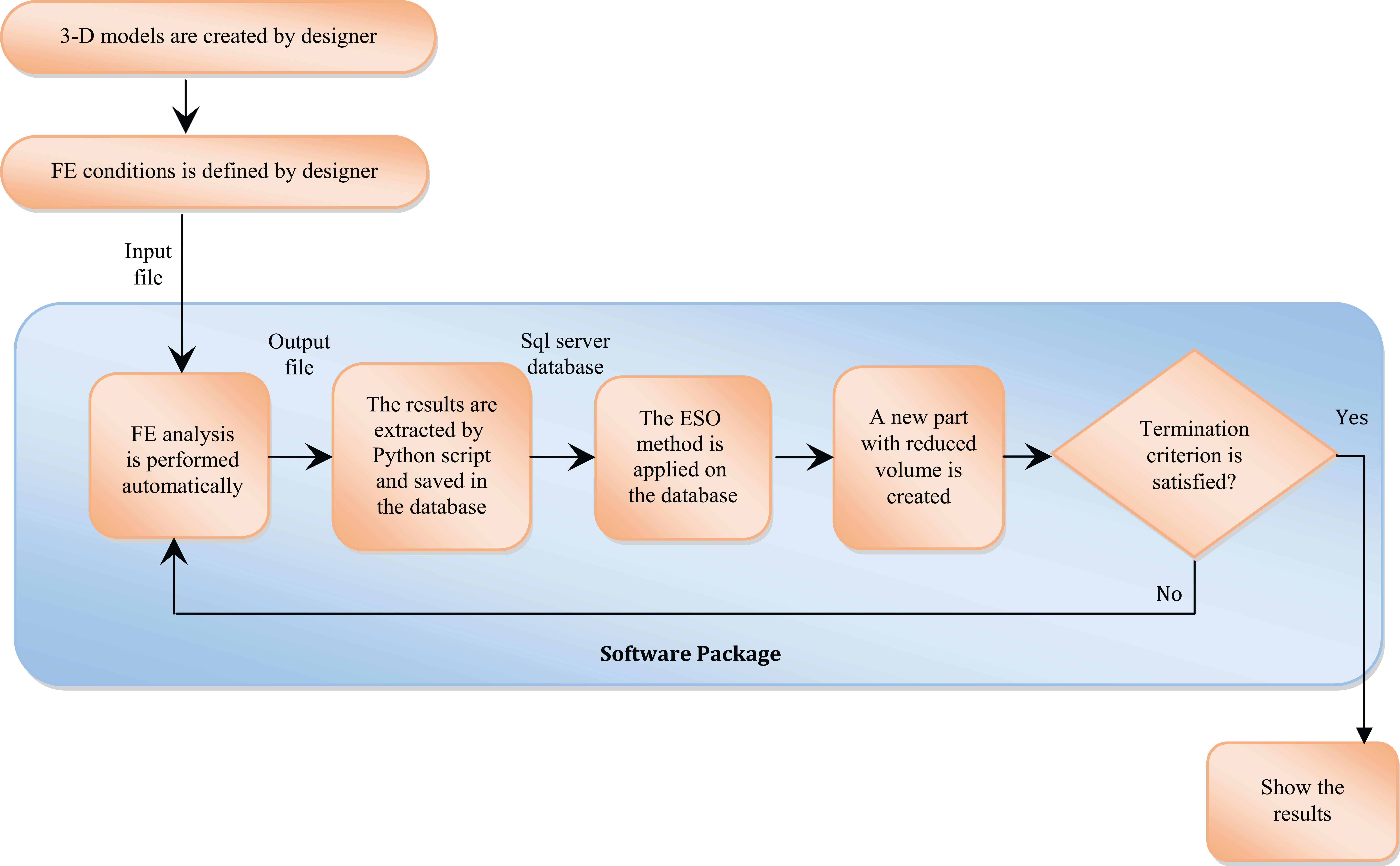
Software package structure.
To define the termination criterion, the stress and strain values of all elements are determined in the whole volume of the parts. If there is a volume reduction at a stage, one of the following two cases occurs, the software terminates the optimization cycle and the part structure in the last step is determined as the final topology with the minimum weight. These conditions are as follows:
One element from the part reaches its maximum allowable stress.
One node from the part reaches its maximum allowable strain.
Maximum values of allowable stress and strain are determined according to the part material and safety factor which is defined by the designer.
The structure is free to take any shape within the given design space in topology optimization. The developed design is often not easy to manufacture which is a concern in topology optimization procedure. However, the designer can modify the final topology to satisfy the casting conditions.
Results and discussion
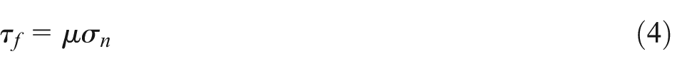
A step box stamping is adopted in this study to show the result of the proposed algorithm (Figure 7). The size of the blank is 1200 × 800 × 1 mm3. The blank is located on the die face. The punch is core and the die is cavity. The die component dimensions are 1500 × 1000 × 400 mm3. The ESO method is carried out on the die component. This procedure can also be applied to any other main components of the die. The structure of the die is divided into fine hexahedron solid elements with the average size of 10 mm. However, the sheet metal blank is divided into quadrangular shell elements with the size of 10 mm. The material of the die and the sheet metal blank are set to be cast iron GGG60 and D275, respectively. The friction contact between sheet and die components follows Coulomb’s law (equation (4))
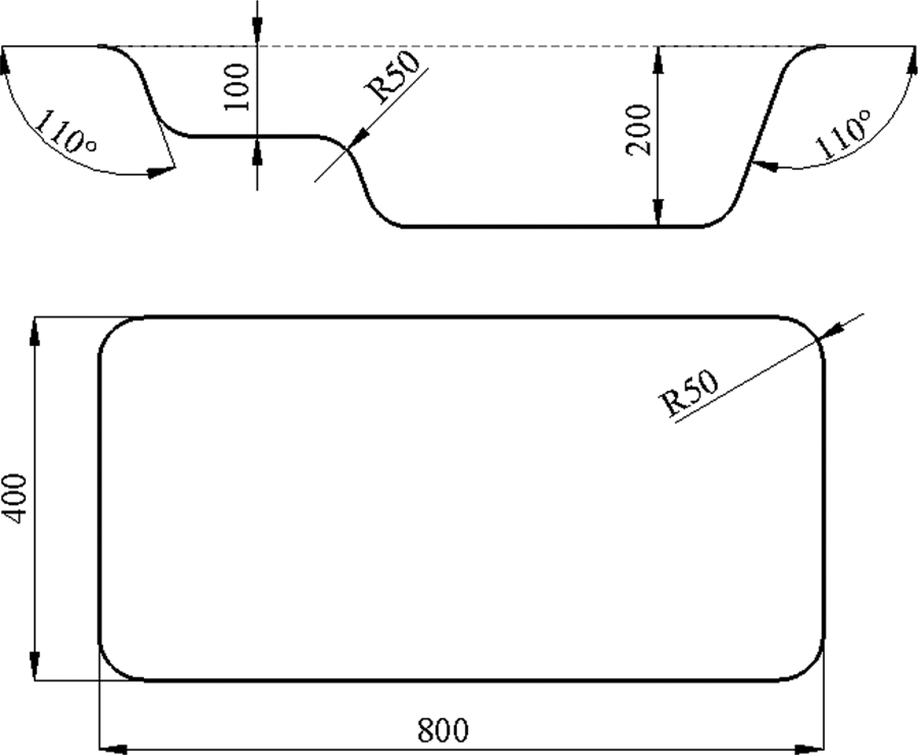
The dimensional information of the step box (mm).
where τf is the friction shear stress, σn is the normal stress at interface and μ is the friction coefficient which is assigned as 0.12. As stated, all die components are modeled as deformable solid parts. The die is constrained in both displacement and rotation in all directions in the global coordinates, while the punch and blank holder are allowed to be translated in the press movement direction. The termination criterion of volume reduction in the software package in iteration 1 is to achieve one-third of the volume of the solid die.
Simulation of the process is implemented in Abaqus/Explicit environment. This process is carried out in three main steps. These are as follows:
The sheet metal deformation due to its gravity when placed on the die;
The fixing of the sheet metal on the die face by the blank holder;
The final movement of the punch for forming the sheet metal part.
Topology optimization results
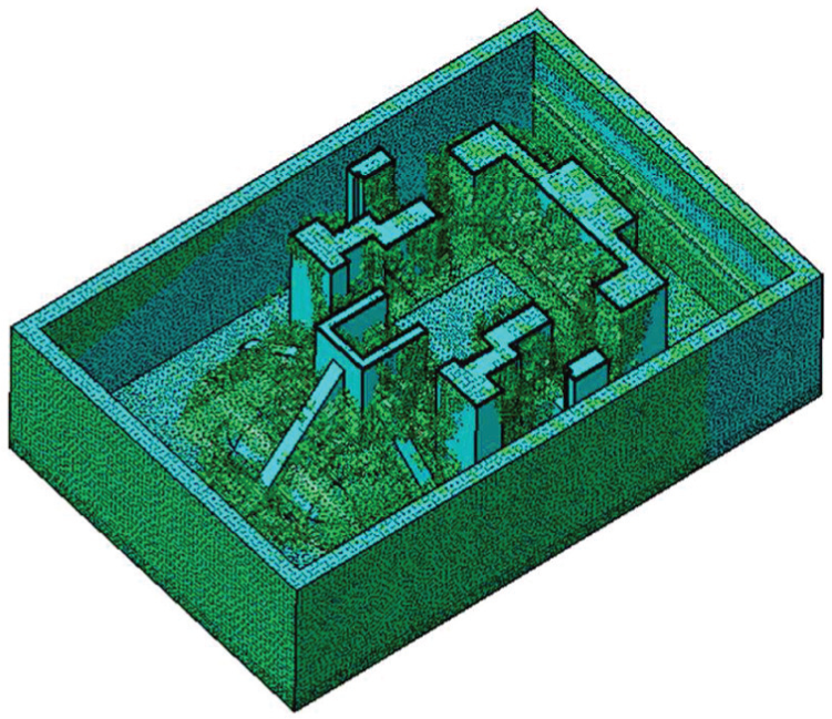
The results from the topology optimization are shown in Figure 8. These are the final results which satisfies the termination criterion and the constraints. The outer frame in the figure is set as non-design space and therefore it will remain unchanged throughout the topology optimization procedure.
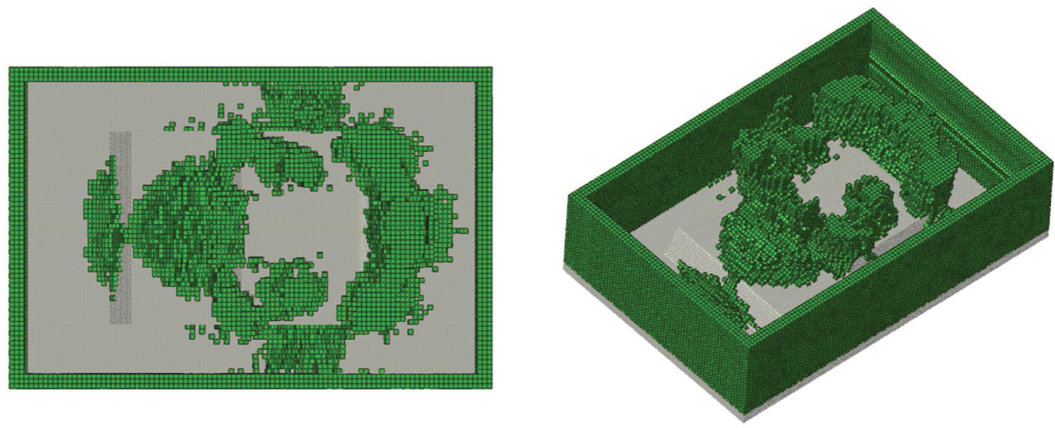
Results from the topology optimization of the die.
Re-design of the die
A CAD model (Figure 9) is created from the pattern seen in Figure 8. As it can be seen in Figure 9, the non-design surfaces are maintained and the new rib structures are created over the volume of maintained elements in the CAD model. The final modified and standard die is shown in Figure 10. As it can be seen, this procedure is very complex without having first the results from the topology optimization (Figure 8).
Re-design of the die.
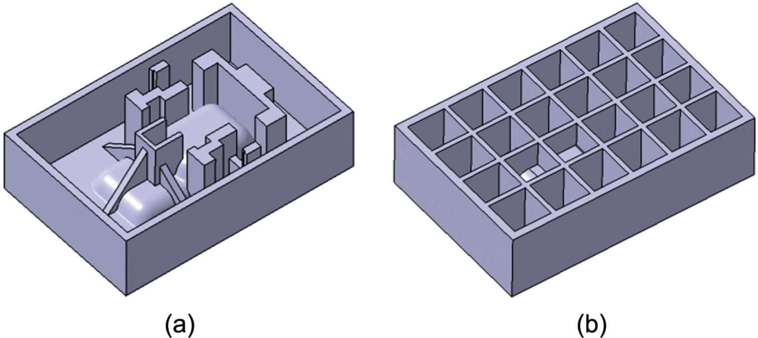
(a) Modified die and (b) standard die.
Displacement and stress analysis of the modified die
To analyze the results of the modified die, the displacements and Von Mises stresses in the standard and modified dies are compared. Results and analysis of the displacements are shown in Figure 11 and the stresses in Figure 12. Table 1 shows the numerical values of the displacements, stresses and weight in the iterations.
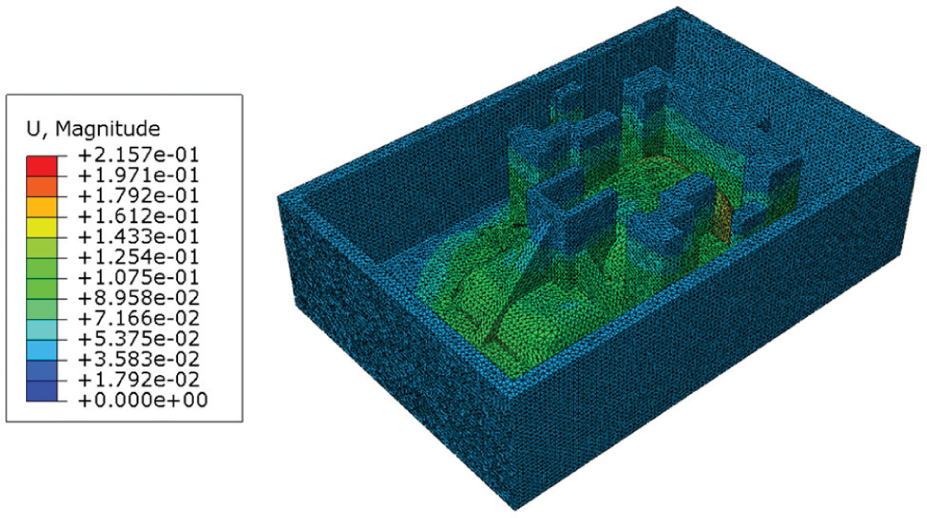
Displacement analysis of modified die (iteration 3).
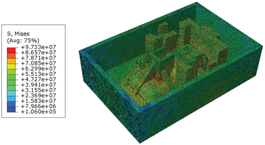
Von Mises stress analysis of modified die (iteration 3).
Comparison between standard and modified dies.
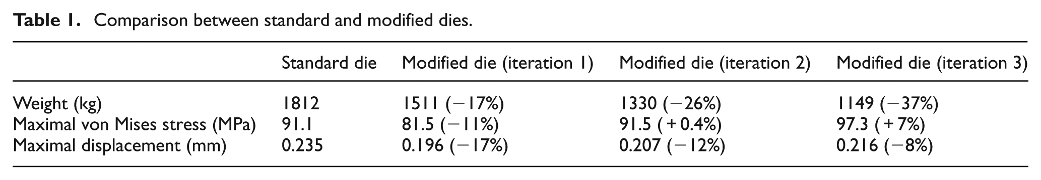
The weight of the modified die is 17% lighter than the standard die, while its maximum displacement is also 17% less than the standard die. The maximum stress on the elements of the modified die is 11% smaller than the standard die.
As it can be seen in Table 1, the maximum stress in the modified die in iteration 1 is less than the standard. So, the weight reduction can still take place by assuming that the maximum stress value be equal to maximum stress in standard die. By reducing the thickness of walls that tolerate less stress, a 26% lighter die is obtained in iteration 2. In this case, the maximum displacement is still about 12% below the standard.
A 37% lighter die can also be obtained if a 7% increase in maximum stress is assumed by the user (this may be due to the fact that a high safety factor is usually assumed for standard dies). This is shown in iteration 3. The maximum displacement is still 8% less than the standard die.
Conclusion
In this study, a software package is developed based on ESO algorithm. Using this software, high- and low-pressure areas in large components of sheet metal forming dies are determined. The material in low-pressure areas is gradually removed and remains constant in high-pressure areas, while the maximum allowable load capacity of the components is maintained at all times.
An example is presented in this article and the whole modification procedure is shown. The modified dies are analyzed and compared with the standard die (the die which is in general use today) regarding the maximum displacement, the von Mises stress and the weight. The final results show a reduction of 37% of volume and 8% of the maximum displacement, respectively.
The software package is developed in Microsoft visual C# environment. Also, a subroutine in Python is developed and used for data extraction form Abaqus output files. Using MS visual C# environment and Python scripts proved to be suitable development tools for this work.
Footnotes
Appendix 1
1. Prerequisites
Model parts in CAD software (Catia)
Transfer parts to FE software (Abaqus)
Define design domain, loads, boundary conditions and FE mesh
Carry out FE analysis
Initialize ER and RR for ESO algorithm
2. Input
Read the file with input format (*.inp)
Repeat
3. Finite element analysis:
Carry out FE analysis in Abaqus software
Create results with output format (*.odb)
4. Extract data:
Open and read odb file
For any part
If part is solid and deformable
For any step in operation
For any frame in sheet metal forming
For any element
Extract the value of von Mises stress
Save to SQL server database
Next element
For any node
Extract the value of displacement
Save to SQL server database
Next node
Next frame
Next step
End if
Next part
5. Topology optimization (ESO algorithm):
For any element
If
Remove the element e
End if
Next element
If any element is not removed (steady state) then
RR = RR + ER
End if
Until satisfy termination criterion
6. Output:
Save as the results with input format (*.inp)
7. End
Declaration of conflicting interests
The authors declared no potential conflicts of interest with respect to the research, authorship and/or publication of this article.
Funding
The authors received no financial support for the research, authorship and/or publication of this article.