
Abstract
Aiming to obtain the acoustic attenuation performance of exhaust muffler of diesel engine and the influence of main structural parameters on its acoustic attenuation characteristics, the finite element analysis method and acoustic theory were adopted to numerically investigate the acoustic attenuation performance under the boundary condition of acoustic adiabatic propagation and muffler wall. It suggested that the noise cancellation effect of muffler was poor at the middle and low frequency in range of 0–3000 Hz, and the transfer loss of muffler was basically 0 dB pass frequency at 1100 Hz. According to previous single-factor study experience, the structural factors, such as the expansion ratio, insertion length of outlet perforated pipe, the distance between the diaphragm and the front part of muffler, have influences on the acoustic performance of muffler at low frequency. Thus, they were taken as the starting point to study the influence of multiple interaction factors on the muffling performance by using orthogonal design method combined with the finite element analysis method. The influence degree of different structure parameters on the acoustic performance of muffler and the optimized structure parameters were obtained. Through the analysis on the acoustic characteristic of the optimized muffler, it indicated that the transmission loss of the improved muffler had significant increase in other frequency range except the range of 650–800 Hz and 2500–2700 Hz, especially at frequency of 1100 Hz compared with the original muffler. In the range of 0–3000 Hz, the mean of transmission loss of the improved muffler was about 9.8 dB larger than that of original muffler, which indicated that better noise cancellation effect was achieved. The improved muffler also provided a certain reference for the structural improvement of similar muffler.
Introduction
The present investigation on diesel engine emissions mainly focuses on exhaust gas recirculation and attenuation of exhaust noise for the serious air pollution and the noise pollution.1,2 Exhaust muffler is one of the effective ways to reduce the exhaust noise of diesel engine, and its acoustic attenuation performance directly determines the exhaust noise of the engine. To achieve better muffling effect, the optimized design and performance improvement of muffler have become the research content of many scholars.3–5 In recent years, the transfer matrix method, three-dimensional analytical method, and finite element method (FEM) have been used on the acoustic performance of the muffler for a large number of studies.6,7 Xiang et al. 8 used transfer matrix method to analyze the acoustic characteristics of the multichamber muffler, and the analytical approach was validated by experimental results. Besides, the effects of several structural parameters on the transmission loss value were studied, including the radius of the baffle holes, the inlet and the outlet, as well as the lengths and the radius of the expansion chambers. Fang et al. 9 used the numerical modal matching method to solve the muffler sub-domain structure transfer matrix, and combined with continuous conditions to obtain the whole matrix of the muffler. This method could predict the muffler acoustic characteristics quickly and accurately. Abdullah et al. 10 used transfer matrix method combined with computer programming to predict the transmission loss of the muffler and verified the analysis results by experiments, and the result showed that the muffler’s expansion ratio increases, the acoustic attenuation performance would increase in the low-frequency band below 1000 Hz as well. Mimani and Munjal 11 used a 3-D semi-analytical method employing a uniform piston-driven model and Green’s function technique to analyze a hollow elliptical chamber muffler with an end inlet and a side outlet. They discussed at length the effect of the offset end inlet at arbitrary location on the end face, and also for arbitrary angular and axial location of the side port in detail to attain a fairly broadband attenuation pattern. Sahasrabudhe et al. 12 used matrix cohesion techniques and transfer matrix techniques to obtain excellent agreement with analytical and experimental results in the form of muffler performance parameters. Guo et al. 13 designed the transmission loss of the analog muffler of the transmission loss test equipment based on the double load method. The results showed that the FEM with detailed perforation modeling had a good consistency with the frequency and amplitude test results over the entire frequency range. Sagar and Munjal 14 used the transfer matrix method to predict the characteristics of the three-pass double-reversal muffler which was redesigned and verified by FEM. However, there are some limitations to analyze the acoustic characteristics of the muffler by using transfer matrix method and three-dimensional analytic method. The development of transfer matrix method which can calculate the acoustic characteristics of the muffler accurately within the plane wave cutoff frequency is based on the plane wave theory.15,16 When the frequency of the noise exceeds the cutoff frequency, the calculation results will gradually deviate from the actual measured value. For the three-dimensional analytic method, it is more suitable for simple structure and regular shape of the muffler acoustic analysis. Actually, when using the transfer matrix method and three-dimensional analytical calculation method to analyze muffler products, because of its complex and irregular internal structure, the deviation between the calculated results and the actual measured values is relatively large. With the maturation of finite element theory and the rapid development of computer technology, the FEM and computer technology can be combined to achieve the acoustic characteristics of any complex shape muffler analysis. It also shows in many literatures that by combining the FEM and computer simulation technology, the influence of structure parameters on the performance of the muffler can be analyzed effectively. Meanwhile, the improved structure parameters of muffler can be proposed according to the calculation results, and finally better acoustic performance can be achieved. Chiatti and Sestieri 17 used the finite element–transfer matrix combination method to analyze the static and dynamic structural problems. Combined with the study of finite element and transfer matrix technique (FETM), some results of the natural frequency vibration of the thin plate were given. Murali et al. 18 used three methods which included the transfer matrix, experimental study, and finite element to calculate the transmission loss of expansion muffler. It showed that the finite element analysis result was closer to the experimental measured results, and transfer matrix method was close to the experimentally measured results only in the low-frequency band. Li et al. 19 and Zhao et al. 20 designed compressor inlet muffler by using the FEM and calculated the transmission loss. And the feasibility of finite element analysis was verified by experiments. Based on the FEM, Krynkin 21 combined ANSYS with MATLAB to improve the structure of the muffler and got better performance of the muffler. Guhan et al. 22 mitigated the weight of existing exhaust systems by optimizing the muffler volume with the 3D design tool CATIA V5 and the computational fluid dynamics commercial tool ANSYS CFX. Existing mufflers were analyzed and physical tests were performed at the vehicle level. Physical test results showed that optimizing the structural parameters of the muffler not only enables the muffler to have better performance but also provided cost-effective and fuel economy advantages. 23 Fu et al. 24 studied acoustic characteristics of agricultural diesel engine by using automatic matching boundary layer FEM and verified the reliability of finite element simulation analysis through experiments. Finally, some structural parameters of the muffler were proposed to improve the muffler’s acoustic properties. Bian et al. 25 used GT-Power software to establish a gasoline engine and its exhaust system coupling model to simulate and analyze the structure of the main muffler and auxiliary muffler exhaust noise, engine performance, and exhaust system parameters. The research showed that when the cavity volume of the muffler was within a certain range, the acoustic attenuation performance would gradually enhance as the volume of the cavity increased. Banerjee and Jacobi 26 applied numerical matching and three-dimensional FEM to the muffler. The results showed that by setting the specific length of the cannon and the position of the inlet and outlet, the muffler’s passing frequency could be eliminated, thereby improving the muffler’s acoustic attenuation performance in the low frequency. Banerjee and Jacobi 26 used finite element software ANSYS and acoustic software SYSNOISE to analyze the expansion muffler. It was found that the transmission loss of the muffler would increase in the middle- and low-frequency bands and the peak value would move to the low-frequency direction when the insertion length of the inner tube increased. In a word, through the combination of FEM and Computer Aided Engineering (CAE) software, analysis on acoustic characteristics of mufflers with different shapes and specifications can be carried out, meanwhile, design and structural improvement of muffler can get effective guide. 27
However, there are certain limitations by using such single-factor method, since different structure parameters have different acoustic attenuation effect on sound waved in different frequency bands. 28 For complex mufflers, acoustic attenuation performance may depend on the common effect of multiple structure parameters. The muffler with only a certain structure parameter improved may have good silencing effect only at a certain frequency segment, and there are doubts whether the improvement of this structure parameter has influence on the noise cancellation effect of other structural parameters. Therefore, it is necessary to consider the relationship between the structural factors and the effect on the performance of the muffler during the structural design and improvement of the muffler.
This paper took the exhaust muffler of diesel engine as the research object. By using the finite element analysis method combined with orthogonal experiment design method, the influence degree of the structure parameters on the acoustic attenuation performance of the muffler was studied and the structure parameters optimization were obtained. It achieved better noise cancellation effect and provided a certain reference for the structural improvement of the similar muffler.
Mathematical model
The evaluation indexes of the acoustic performance of the muffler are mainly evaluated in four quantities which are the transmission loss (LTL), the insertion loss (LIL), the end noise reduction amount (LNR), and the noise attenuation amount (NR). The muffler measurement value of the muffler is related to the method used and the external environment, and the method used in different environments is different. In the selection of evaluation indicators, it is necessary to comprehensively consider the influence of various factors. Therefore, this paper chose transmission loss as the evaluation index of the research. In general, the sound field characteristics of sound can be described by physical quantities, such as sound pressure, particle vibration velocity, and density variation in the propagation medium. In the process of transmission, the sound wave usually causes a small disturbance of the environmental state, and the Helmholtz equation can be used to realize the quantitative analysis of the sound field.

When the acoustic field inside the muffler is discretized into a finite number of muffler units
Appyling Green formula to transforming the first integral of formula (3) can get:

The sound pressure
Bring formula (5) into formula (4), eventually can get:

With all the finite elements in the acoustic field assembled, the acoustic finite element equations are finally obtained

Based on the boundary conditions, the acoustic pressure values of all nodes can be obtained by solving equation (7).
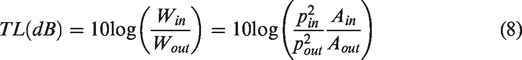
The transmission loss of the muffler is defined as the difference between the incident sound power level and the output sound power level, and the muffler transmission loss calculation formula is:
When the boundary conditions at the ends of the inlet and outlet of the muffler are given, the transmission loss of the muffler can be obtained combining formulas (5) and (6).
Finite element model
Structure of muffler
The structure of muffler is shown in Figure 1. The muffler is mainly constituted of outlet perforated pipe 1, expansion chamber 2, sieve pore diaphragm 3, inlet perforated pipe 6, etc. Expansion chamber 2 is divided into two resonant cavities B and C by the sieve pore diaphragm 3, the specific parameters of each structure of which are shown as Table 1. The expansion ratio of the muffler is
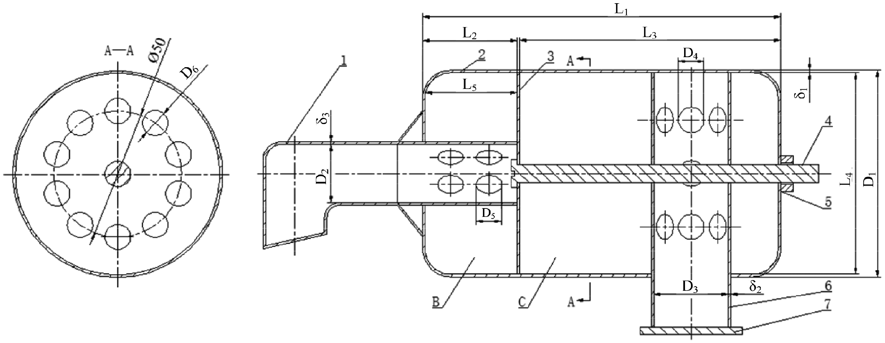
Schematic diagram of structure. 1: outlet perforated pipe; 2: expansion chamber; 3: the sieve pore diaphragm; 4: connecting screw; 5: fastening nut; 6: inlet perforated pipe; 7: mounting bracket; B: the second resonant cavity; C: the first resonant cavity; D1: diameter of cavity; D2: diameter of outlet perforated pipe; D3: diameter of inlet perforated pipe; D4: pore size of inlet perforated pipe; D5: pore size of outlet perforated pipe; D6: pore size of the sieve pore diaphragm; δ1: the wall thickness of cavity; δ2: the vertical wall thickness of outlet perforated pipe; δ3: the wall thickness of outlet perforated pipe; L1: the length of cavity; L2: the length of the second resonant cavity; L3: the distance between the diaphragm and the front part of the muffler; L4: insertion length of inlet perforated pipe; L5: insertion length of outlet perforated pipe.
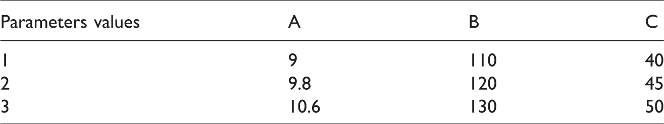
The parameters of structure.

Discretization of model
Based on the discretization of the acoustic region inside the muffler, to ensure the accuracy of acoustic calculation, the maximum length of divided grid units is limited to 1/6 of wavelength at the highest frequency point, shown as the formula
Since the exhaust noise of the diesel engine is mainly at the mid-low frequency, the
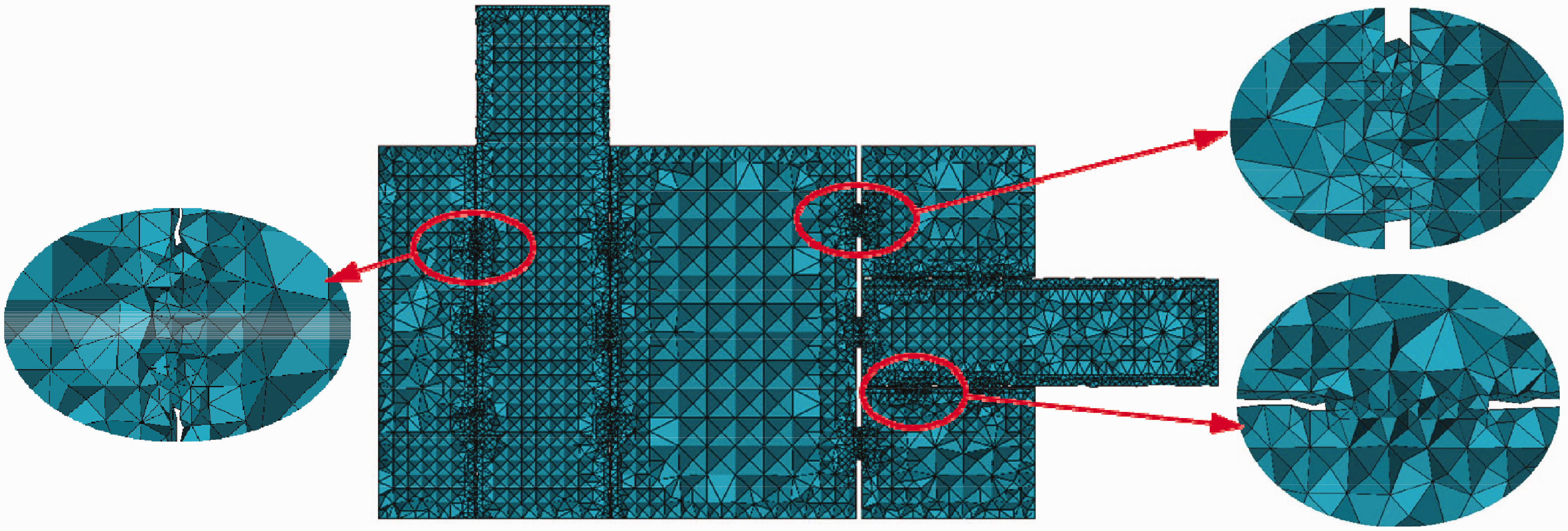
Finite element grid.
Boundary condition setting
The boundary conditions when calculating acoustic finite elements were listed below:
To facilitate the transfer of loss calculations, the inlet boundary was defined as the unit particle velocity that was The outlet boundary was defined as a nonreflecting boundary condition which was valid for plane waves that was The exhaust noise is mainly low and medium frequency. For the thick and rigid wall of muffler, the wall boundary was defined as a rigid wall without considering wall absorption. The normal velocity was zero, which was
Analysis on results
Combined with the boundary conditions and formula (7), acoustics pressure values of any node could be obtained. According to transfer loss formula (8), the calculated transfer loss of the muffler is shown in Figure 3. It suggests that the noise cancellation effect of muffler is poor at the middle and low frequency in range of 0–3000 Hz, and the transfer loss of muffler is basically 0 dB pass frequency at 1100 Hz. It can be seen that transfer loss of muffler near 1100 Hz is relatively low, especially the transmission loss is basically 0 dB pass frequency at 1100 Hz, the noise reduction effect is very poor and the transmission loss value at around 2300 Hz is at most 63 dB. The noise reduction effect in the frequency range of 1–1100 Hz is relatively poor, and the average transmission loss is less than 10 dB. The noise reduction effect in the frequency range of 1100–2000 Hz is generally that the average transmission loss is less than 15 dB. The noise cancellation effect is better in the frequency range of 2000–3000 Hz for the average transmission loss is about 25 dB. On the whole, the average transmission loss of the muffler in the frequency range of 1–3000 Hz is about 19 dB and the effect was poor. Therefore, it is necessary to improve the structure of the muffler to increase the transfer loss.
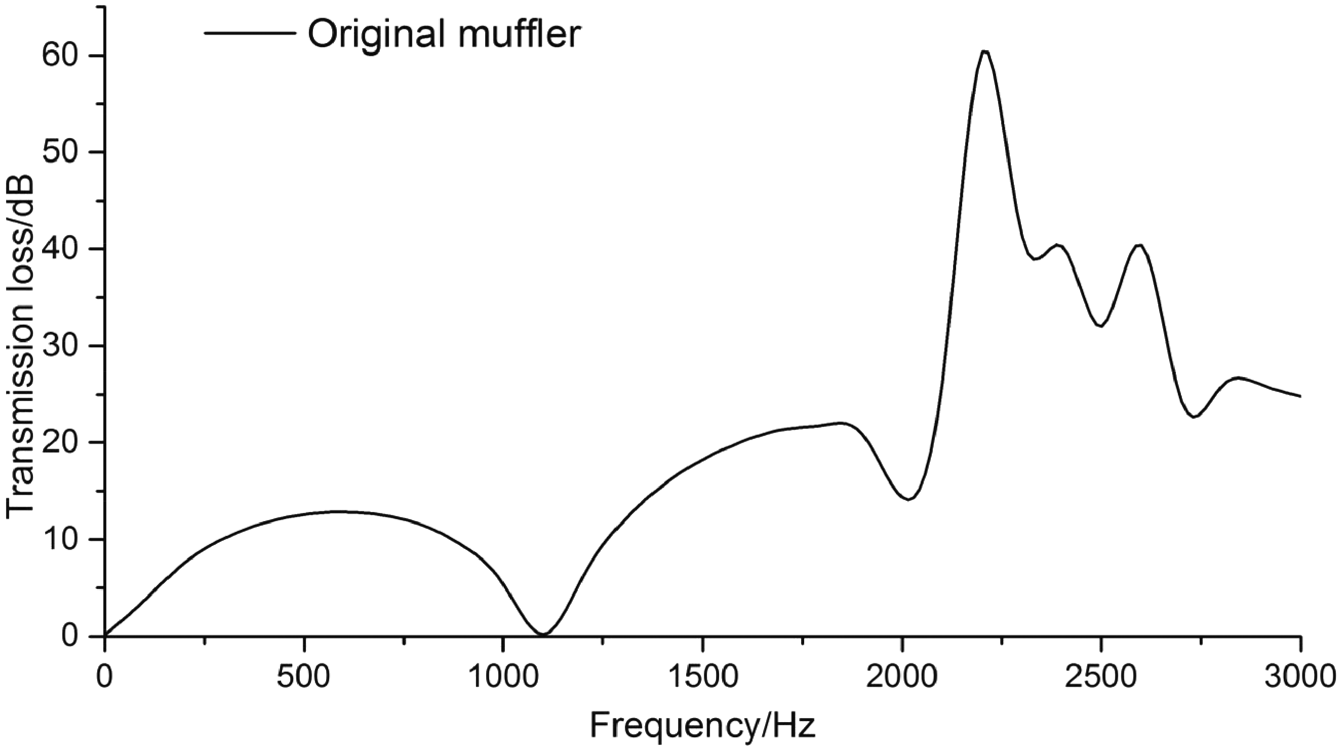
Transmission loss curve of the muffler.
Analysis on structure improvements
As suggested above, different structure parameters have some influences on the performance of the muffler. The intention or purpose of this study is to improve the muffling performance of diesel exhaust muffler in the mid-low frequency range of 1–3000 Hz. From the study of the influence of structural parameters on the performance of muffler and the analysis of the structural parameters of muffler, it is easy to know such a message. That is the structural parameters existing in the muffler that affect the low-frequency muffling performance include an expansion ratio (m), an outlet pipe insertion length (L5), a mesh hole partition relative to the muffler front end position (L3), and the like. This paper uses orthogonal test design method and finite element analysis method to analyze it. The influence of these structural parameters on the performance of the muffler was obtained, and the structural parameters of the muffler were optimized.
Determination on test factors and level
To study the influence degree of structure parameters on the acoustic attenuation performance of the muffler and improve the performance at middle frequency and low frequency, according to the basis of previous studies, the structural parameters of the muffler were reasonably selected, such as total length, expansion ratio (m), mesh separator, and so on. The structural parameters of muffler are designed, such as the length of the muffler, the expansion ratio m, the insertion length of outlet perforated pipe (L5), the distance between the diaphragm and the front part of the muffler (L3) etc, while other parameters unchanged. The length of the cavity of the muffler took 190 mm. The expansion ratio (m), the insertion length of outlet perforated pipe (L5), the distance between the diaphragm and the front part of the muffler (L3) are set as test factors A, B, C individually. The values of corresponding levels 1, 2, 3 are shown in Table 2.
Factors and levels of orthogonal experiment design.
Determination on test scheme
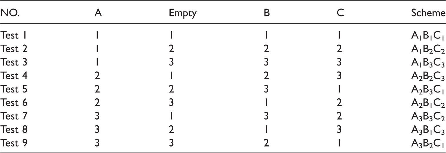
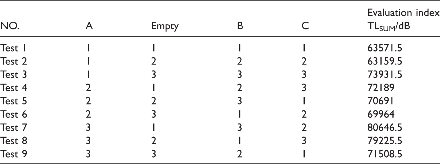
According to Table 2, the test factors corresponding to the expansion ratio (m), the insertion length of outlet perforated pipe (L5), and the distance between the diaphragm and the front part of the muffler (L3) are designed as three level values. Based on standard orthogonal experiment table, T9(34) orthogonal experiment table is chosen to design orthogonal experiments. Nine test schemes with different structure parameters are determined, which are shown in Table 3.
The orthogonal experiment schemes.
Analysis on the experiment results
The separate calculation results of the nine schemes in Table 3 by using acoustic finite element analysis method are shown in Figure 4.
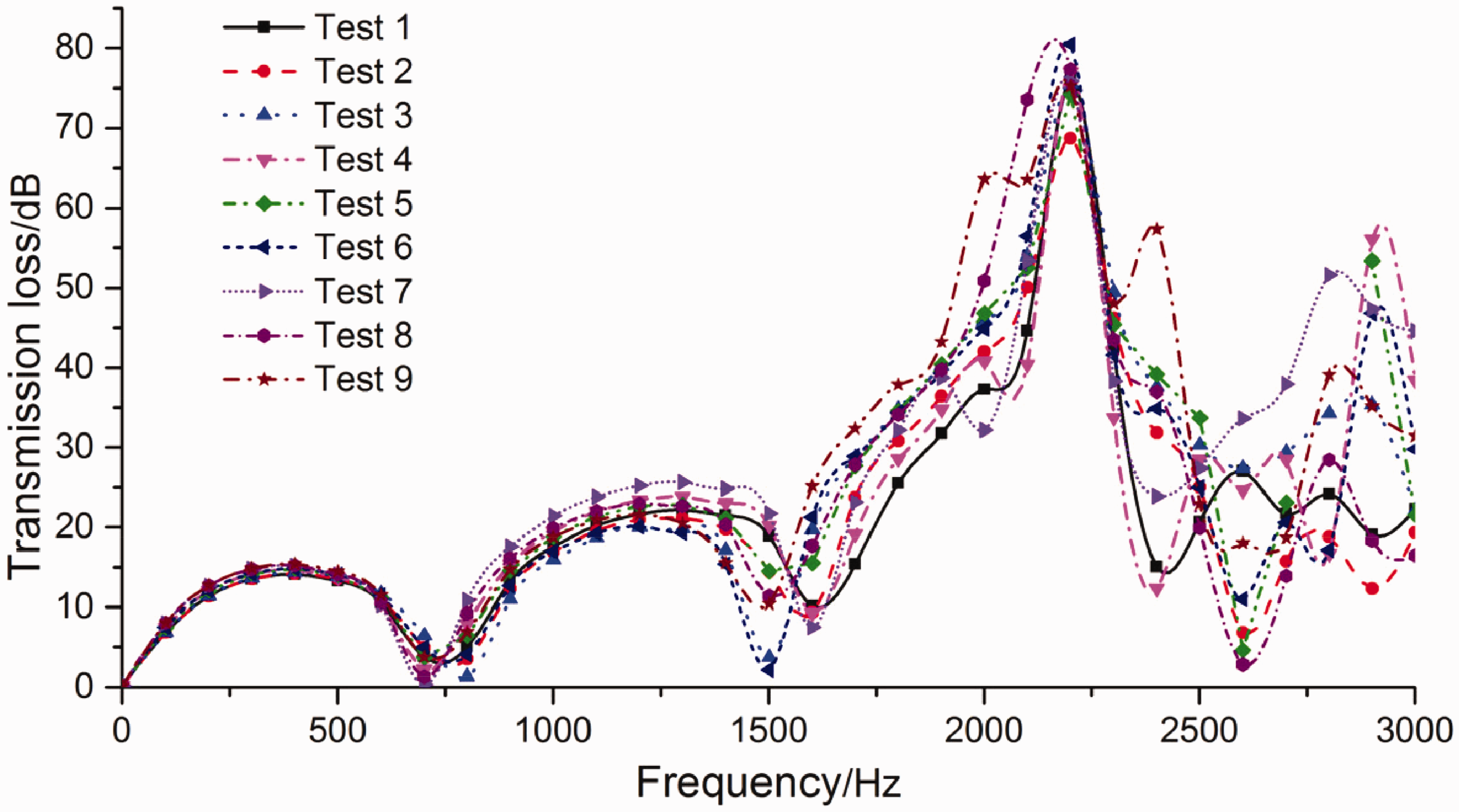
The transmission loss curves of nine test schemes.
It can be seen from Figure 4 that the transmission loss of the muffler in the nine groups of tests is shifted to the low-frequency direction relative to the original muffler, and the spacing between the peaks of the transmission loss corresponding to the transmission loss in 0–1600 Hz is reduced from and within the range of 1600–2400 Hz. The amount of noise reduction is larger than that of the original muffler, which proves that the muffler scheme obtained in the nine groups of experiments is better than the muffler performance of the original muffler in the middle- and low-frequency bands.
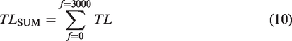
Based on the obtained calculation results, the transmission loss sum (TLSUM) of muffler in the frequency range of 0–3000 Hz is chosen as the evaluation index of the acoustic attenuation performance of muffler. The calculation formula of TLSUM is
The evaluation index of each scheme can be obtained based on the sum of the calculating results of transmission loss, as shown in Table 4.
The test results.
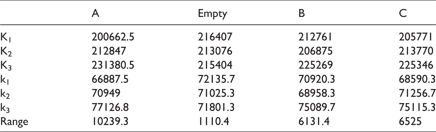
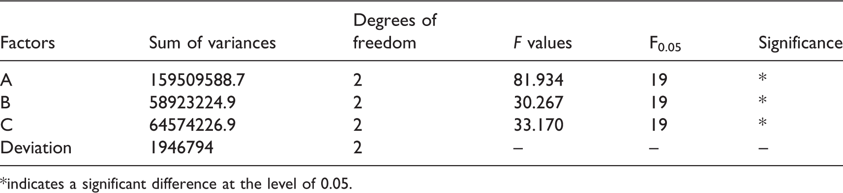
In order to exclude the influence of random factors, the influence degree of the three structure parameters on acoustic attenuation performance of muffler was studied and the theoretical schemes were optimized. The results of orthogonal experiment were analyzed by using variance analysis. The means and ranges corresponding to each factor were separately calculated, as is shown in Table 5, and the corresponding sum of variances, degree of freedom, and F value etc. are shown in Table 6. In Table 5, K was the transmission loss sum (TLSUM) of muffler in the frequency range of 0–3000Hz, k is the arithmetic means of the evaluation indexes.
The analysis results.
The analysis results of variance.
*indicates a significant difference at the level of 0.05.
It can be seen in Table 5 that with the increase of level values corresponding to factors A and C, the means of the evaluation indexes increased correspondingly. That is within a certain control range, with the increase of the expansion ratio m and the insert length of outlet perforated pipe L5, the noise cancellation effect of the muffler is enhanced. For factor B, the mean value of the corresponding evaluation index is first reduced and then increased. The influence of L3 on the acoustic attenuation performance is relatively complex. As is shown in Table 6, the F values of factor A, B, and C are all larger than critical value F0.05 (the significance level
Determination on optimal scheme
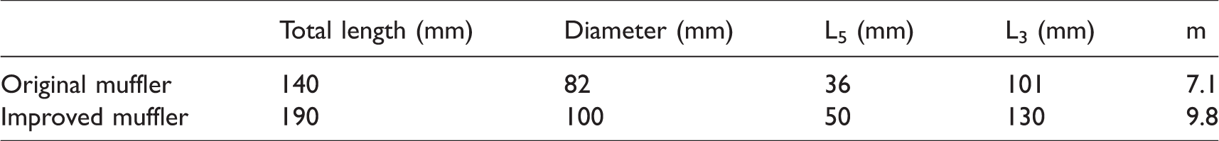
By comparing the arithmetic means ki (i = 1,2,3) of the evaluation indexes corresponding to the structural parameters in Table 5, the biggest ki is the best structure parameter that is the optimal scheme A3B3C3. Figure 5 depicts the comparison of transmission loss results between the optimal scheme A3B3C3 and the best scheme A3B3C2 (Test 7) of the orthogonal experiment table. According to Figure 5, although the transmission loss of scheme A3B3C3 is relatively reduced in certain frequency bands by comparing to scheme A3B3C2, the transmission loss of scheme A3B3C3 is more than that of scheme A3B3C2 on the whole. Accordingly, the final optimal scheme is A3B3C3, and its expansion ratio (m) is 9.8, the distance between the diaphragm and the front part of the muffler L3 is 130 mm, the insert length of outlet perforated pipe L5 is 50 mm. The comparison between the structure parameters of scheme A3B3C3 and the original muffler is shown in Table 7.
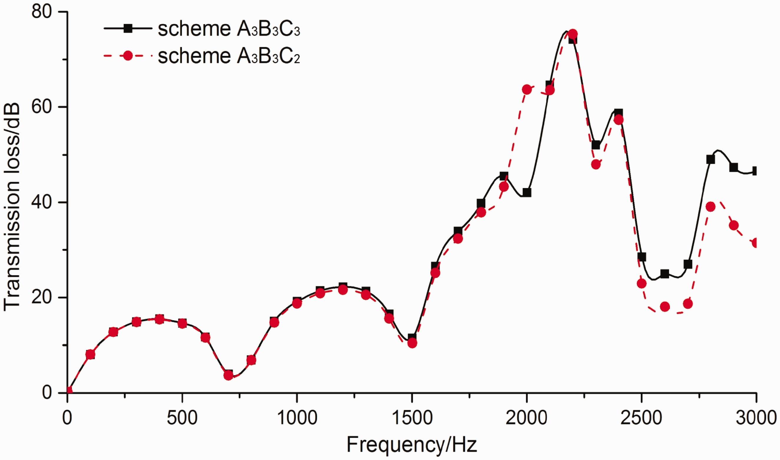
The comparison chart of the schemes.
The comparison table of the structure parameters.
The validation of the optimal scheme
The comparison of acoustic calculation results between the optimal scheme A3B3C3 and the original muffler is shown in Figure 6. It can be seen that compared with the original muffler, the transmission loss curve of the optimal scheme is shifted to the low frequency, the width of each arch is reduced, and the distance between every two arch peaks is reduced relatively. The transmission loss of the improved muffler has significant increase in other frequency range except the range of 650–800 Hz and 2500–2700 Hz, especially at the frequency of 1100 Hz. In the range of 0–3000 Hz, the mean of transmission loss of the improved muffler is 9.8 dB larger than that of the original muffler that achieved better noise cancellation effect.
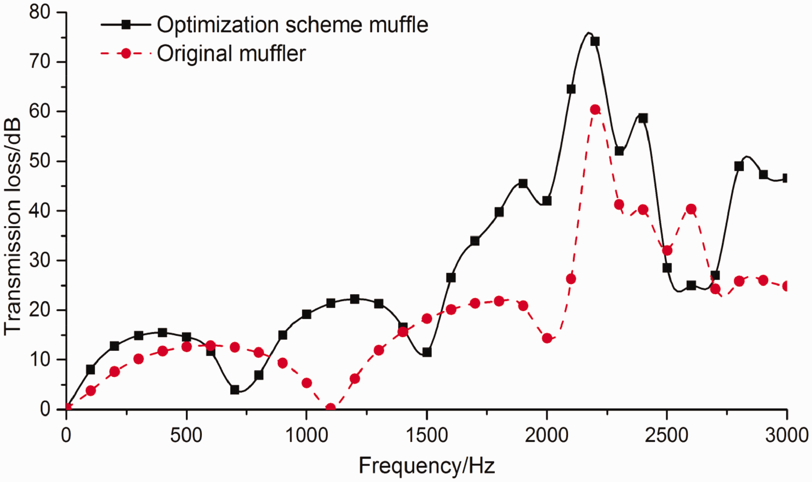
The transmission loss chart of the optimized muffler and original muffler.
Conclusions
In the present work, the mathematic model of the muffler of diesel engine was established based on the finite element analysis method and the acoustic plane wave theory. The muffler characteristic was calculated and analyzed numerically under the boundary condition of acoustic adiabatic propagation and rigid wall of the muffler. Then the acoustic attenuation characteristics of the muffler was obtained. Based on the previous research about the influence of the structural parameters of muffler on its muffling performance, the structural parameters affecting the low-frequency muffling performance have the expansion ratio (m), the outlet pipe insertion length (L5), and the mesh hole separator relative to the muffler front end position (L3) etc. According to the calculation result of the muffler characteristics of muffler, combined with the analysis of the structural parameters of muffler, the orthogonal experimental design method, and the finite element analysis method were used for analysis. The influence degree of these structure parameters on the muffler performance and the optimal structure parameters of muffler were obtained. The results suggested that the three factors had obvious influence on the muffler performance and the influence degree was m > L5 > L3. Through the validation of the obtained optimal scheme in the orthogonal experiment, the results showed that compared with the original muffler, the transmission loss of the improved muffler in the frequency bands of 650 − 800 Hz and 2500 − 2700 Hz was not large. The transmission loss of other frequency bands, especially at the frequency of 1100 Hz, had been greatly improved. In the range of 0 − 3000 Hz, the transmission loss of the muffler was preferably increased by 9.8 dB compared with the original muffler, and a good noise cancellation effect was obtained, which provided a certain reference for the structural improvement of the similar muffler.
Footnotes
Declaration of conflicting interests
The author(s) declared no potential conflicts of interest with respect to the research, authorship, and/or publication of this artic.
Funding
The author(s) disclosed receipt of the following financial support for the research, authorship, and/or publication of this article: This work was financially supported by the National Natural Science Foundation Key Project of China (No. 91541121), Scientific Research Fund of Hunan Provincial Education Department (No. 16B235), Scientific Research Fund of Hunan Science and Technology Department Project (No. 2018GK2074), Hunan Provincial Graduate Research Innovation Project (No. CX2017B794), and Shaoyang College Graduate Research and Innovation Project (No. CX2018SY005).