
Abstract
QZS isolators are particularly useful for low frequency excitations that are difficult to isolate for traditional isolation techniques. These isolators can be designed based on bistable structure which is very simple and of low weight. However, an external rigid restraint in transverse direction is often required for this kind of isolator which severely limits its application. This paper investigates a light-weighted QZS device that shows the QZS regardless of flexibility of the support. The device is based on inclined beams connected axially in series. Mechanism of the structure to generate the quasi-zero stiffness is discussed. A numerical model is developed for predicting its behavior. A series of tests were conducted to validate behavior of the structure and the numerical model, and a thorough numerical parametric study was performed. Based on the results, QZS isolators were designed and tested which is shown to have light weight and a good loading capacity.
Introduction and background
Isolators with quasi-zero stiffness (QZS) are very useful in vibration control as these isolators are effective for low-frequency dynamic excitations which are difficult to control for traditional isolation system.1–8 The QZS characteristics of this kind of isolator is generated by matching components with negative stiffness characteristics with components with corresponding positive stiffness. A variety of mechanisms to generate the negative stiffness were investigated by researchers including the pendulum structures,9–12 magnetics,13,14 anti-springs,15–18 and Euler buckling beams.19–21 In particular, the negative stiffness can be generated by a bistable structure.10,22–25 The bistable structure is a structure that has multiple stable positions introduced by geometric nonlinearity. Between the stable positions, snap-through phenomenon occurs accompanied by sudden switching of the positive stiffness to negative stiffness. Unique advantage of the QZS isolator based on bistable structure is that it can be very simple, without requiring any hinge, prestress, or magnetic force, and is especially useful for shock absorption and base isolation in aerospace engineering which has strict requirement for weight of the isolator. The bistable structure can be simply a curved shell 24 or a curved or inclined beam with horizontal restraint.26,27
The matching of the negative and positive stiffness to generate the quasi-zero stiffness in the isolator is complicated but often necessary for this kind of isolator to work. A high initial stiffness is preferred for the isolator in addition with the low tangential stiffness at the intended working load. The dramatic shift from positive to negative stiffness of the bistable structure associated with the snap-through behavior is therefore often required. For the inclined or curved bistable beam, stiffness of the horizontal restraint is crucial to this behavior. Zhang et al. (2023) 28 found that the peak strength and the negative stiffness both reduce with reduced stiffness of the restraint. The existing study on isolators based on bistable structures, on the other hand, generally assumes a rigid constraint to horizontal stretching of these inclined or curved beams. As a matter of fact, a strong support is often used in isolators and metamaterials together with bistable beams which adds significant dead weight and limits its application.29–33 On the other hand, Zhang et al. (2022) found that when connected in series, axial interaction of bistable beams leads to a plateau in their force-displacement behavior. This approach, effectively, eliminates the requirement for an exact match of the positive and negative stiffness, allowing for boundary support with significantly reduced weight.
This paper investigates this kind of structure, which can generate the quasi-zero stiffness with a high initial stiffness without requiring a strong horizontal support, as well as matching of the negative stiffness generated by snap-through behavior with a corresponding positive stiffness. The structure is based on inclined connected axially in series. The mechanism to generate the quasi-zero stiffness is discussed and numerical models to calculate the force-displacement behavior of the structure is proposed and validated by experimental results. The results show that the structure can generate consistent QZS regardless of the stiffness of the horizontal restraint and the strength and secant stiffness of the structure is unaffected as well. However, there is slightly reduced initial stiffness. As the mechanism has an integrated structure and requires no rigid support for horizontal restraint, QZS isolators based on the mechanism can be very light-weighted. Several isolators were designed and tested based on a series of this kind of structures connected together. Their experimental results are used for further validation of the proposed mechanism.
Mechanism for generating the QZS
Connected inclined beams with negative stiffness
The proposed mechanism is based on a structure shown in Figure 1 which are four identical inclined beams connected together by a rigid link in the middle. The beams are inclined and expected to be affected significantly by geometric nonlinearity. The structure is loaded vertically at one end. In the other end, it is restrained of vertical deformation and rotation, but is allowed of horizontal deformation with a stiffness of k
b
. This kind of boundary condition resembles the structure shown in Figure 1(b). Flexural stiffness of the vertical supporting beam is much larger than that of the investigated structure but its horizontal stiffness cannot be regarded as rigid compared with the axial stiffness of the beam. This is often the boundary condition of real bistable beams. The QZS is generated by axial interaction of these beams. A detailed deduction about the mechanism with a rigid restraint in the horizontal direction is given in Zhang et al. (2022). This paper extends this deduction to a structure with flexile horizontal restraint. Investigated structure for generating the quasi-zero stiffness (a) assumed boundary condition, (b) the structure with a supporting beam with insufficient horizontal stiffness.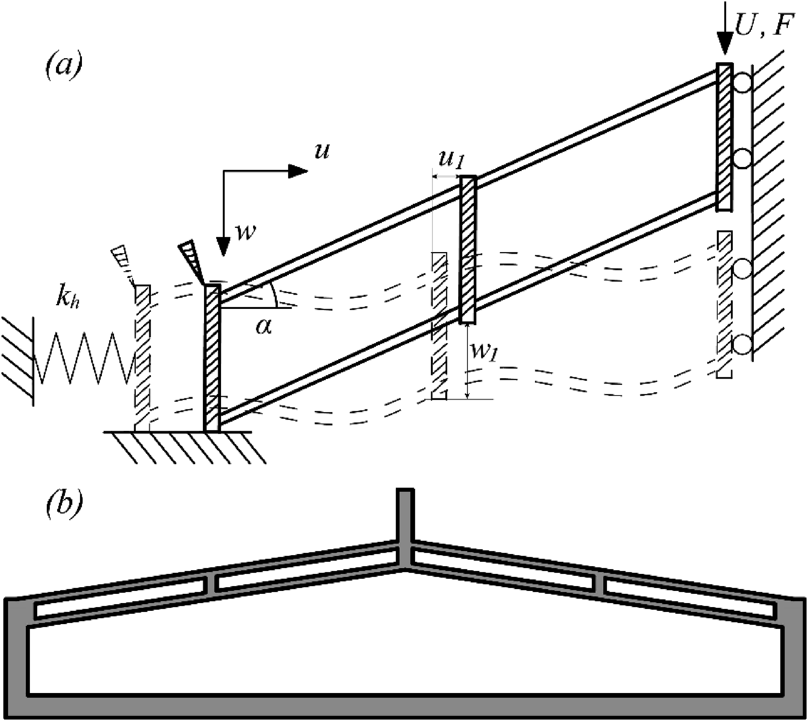
The deformation of the beam in local coordinate in Figure 2 can be transferred from global coordinate in Figure 1(a) by eq. (1) Interaction of the axial deformation of the beam in local coordinate.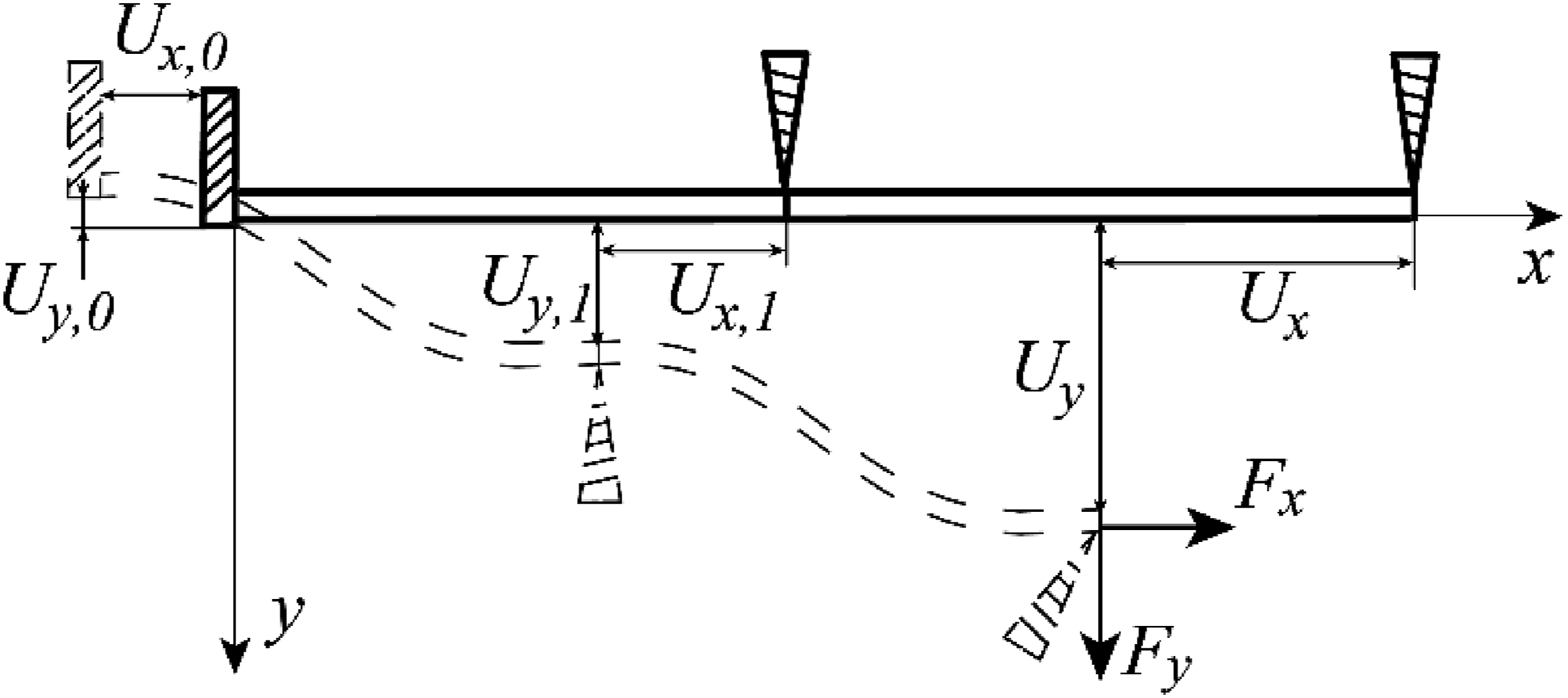

As axial stiffness is generally much larger than the vertical bending stiffness of these beams, deformation of upper and lower parallel beam of the structure is expected to be similar, which allows the structure to be further simplified based on symmetricity, as shown in Figure 2. The total deformation of two beams shown in Figure 2 is in compatibility with horizontal deformation of the base while the vertical and horizontal force of each beam are similar. This assumption will be validated by FE and experimental studies later.
If the two beams are truly identical, the left and right beams are expected to exhibit similar behavior when the structure is imposed with vertical load. However, fabrication errors also always introduce differences in their geometric details and leads to slightly different forces corresponding to the snap-through phenomenon. Due to the negative stiffness followed the snap-through phenomenon, the structure can switch dramatically from its symmetric deformation mode into a deformation mode with concentrated deformation in one beam and relatively small deformation in the other one. Behavior of each beam is therefore affected by their axial interactions. For the beam without snap-through, its behavior can be approximate by eqs. (2) and (3) which is derived from the solution proposed by Awtar et al. (2007).
34
The solution is first order Taylor expansion of the nonlinear governing equation.
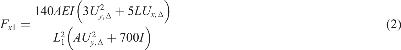

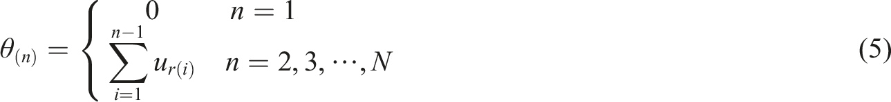
From eqs. (2) and (3), vertical and axial force of the beam without snap-trough can be calculated from deformation at its end. For simplicity, it is assumed that the right beam in Figure 2 goes through the snap-through behavior and shows the negative stiffness earlier than the left beam, which gives Figure 3 relating deformation of the middle link, w
1
and u
1
with axial force of the left beam and the horizontal deformation of the elastic support in Figure 1(a). The results for a beam with a length of 30 mm, thickness of 1 mm, width of 10 mm, and an inclination angle of 10°. Young’s modulus is assumed to be 1000 MPa for the calculation. The horizontal stiffness of the restraint is assumed to be 640 N/mm which corresponds to a supporting column with a thickness of 4 mm and a height of 10 mm shown in Figure 1(b). Variation of the axial force and base deformation of the structure with deformation of the middle link.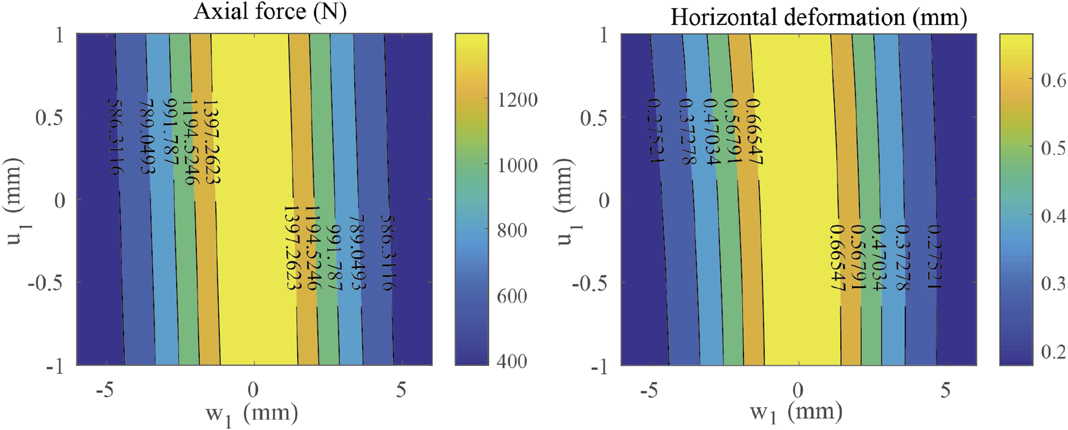
As the figure shows, both the horizontal deformation and the axial force are mainly related with vertical deformation of the middle link. Considering the horizontal stiffness of the beams is much larger than their vertical stiffness, variation of u
1
is also expected to be much less. We therefore ignored variations of u
1
and took the value of axial force and horizontal deformation when u
1
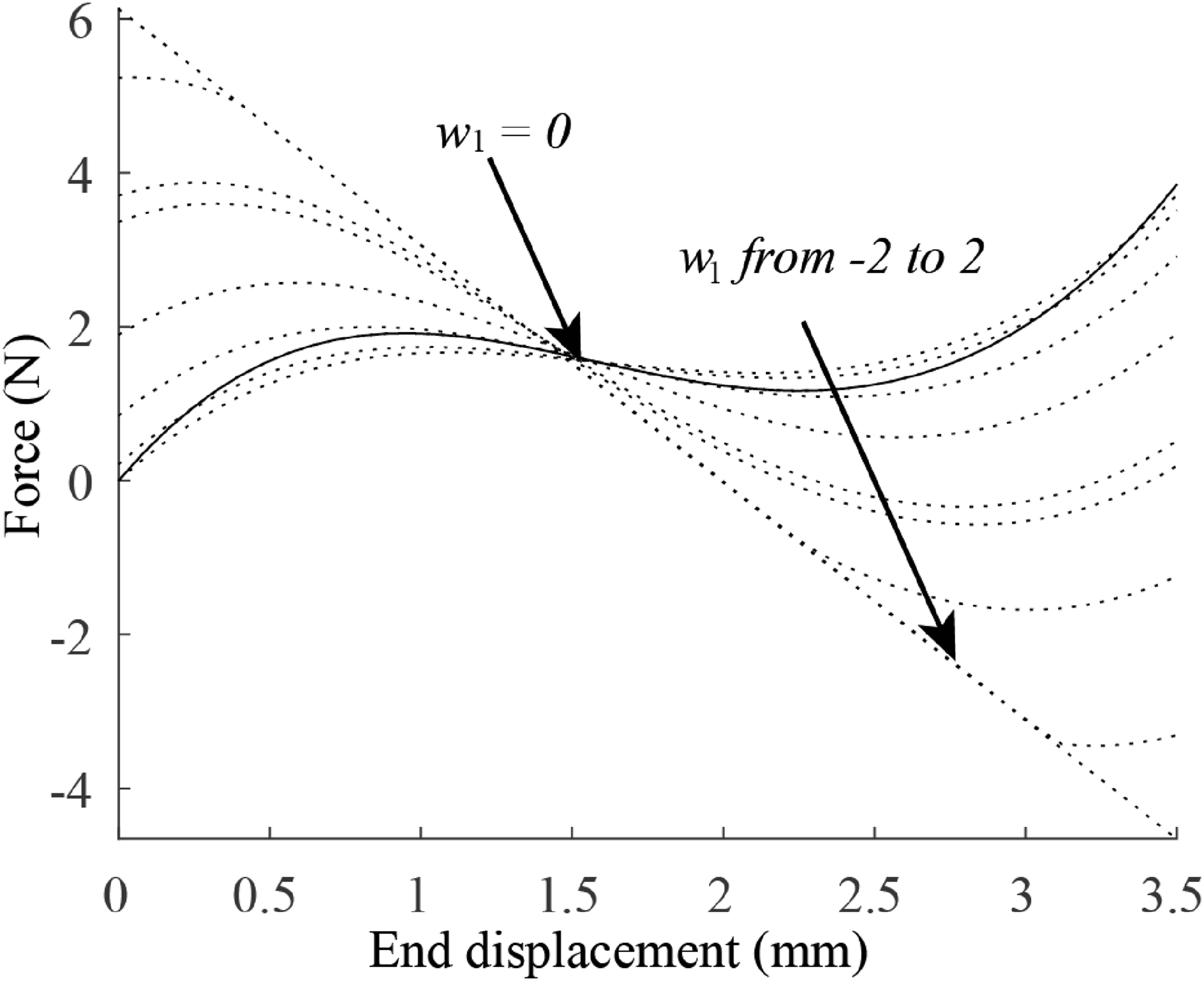
is 0 mm for further calculation. This simplification allows calculating the force-displacement curve of the other beam corresponds to different value of w
1
, as shown in Figure 4. Particularly, the results are given for a structure with k
b
of 640 N/mm and 80 N/mm, individually. These two stiffnesses correspond to a 10 mm supporting structure with a thickness of 4 mm and 2 mm, respectively. The curves shown in Figure 4 indicate the possible equilibrium locations of the middle link of the structure and its corresponding stiffness. Behavior of the overall structure can be evaluated from these curves. In Figure 4, the force-displacement curve of the structure assuming symmetric deformation mode of the connected beams is also given for comparisons. The symmetric deformation mode approximates the initial deformation mode of the structure until the symmetry is broken by dramatic change of stiffness of one of the connected beams associated with the snap-through behavior. In these cases, the structure eventually finds equilibrium locations in one of the dashed lines. Possible equilibrium force-displacement curves of the beam corresponding to different value of w
1
(a) k
b
= 640 N/mm, (b) k
b
= 80 N/mm.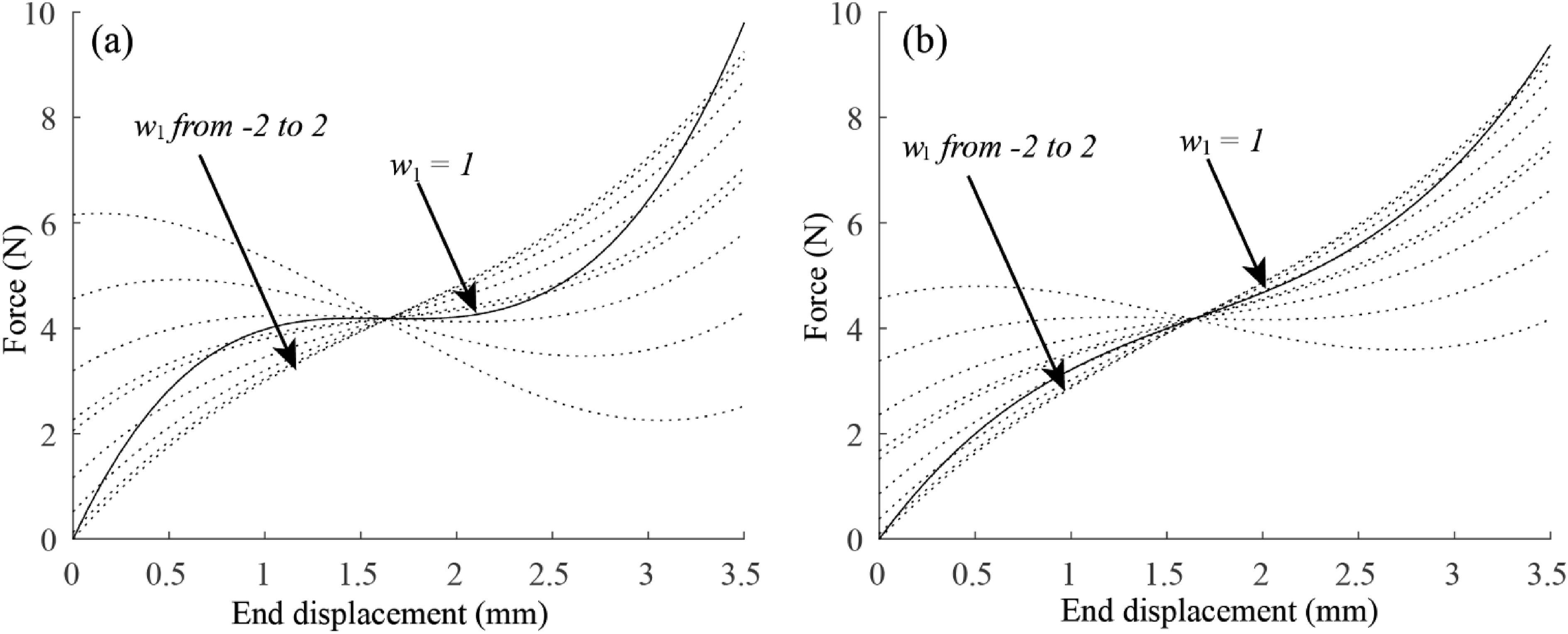
As the structure is imposed with larger vertical deformation, the connected beams find new equilibrium locations with movement of the vertical deformation of the rigid link (w 1 ). From the curves, it can be seen that a higher value of w 1 always introduces reduced vertical force of the snapping beam. w 1 is determined by force equilibrium between the snapping beam and the beam without the snap-through phenomenon acting as restraint (eq. (2)). A reduced vertical force of the snapping beam introduces reduced displacement of the restraining beam, which, in turn, reduces w 1 and leads to an increased vertical force. Similarly, the increase of vertical force of the snapping beam increases w 1 , which leads to change of the axial restraint provided by the other beam. Eventually, behavior of the snapping beam is expected to go to a branch of the force-displacement curve with approximately constant vertical force. The overall structure is expected to go through a force-displacement trajectory with very low tangential stiffness. The trajectory is associated with concentrated vertical deformation in the snapping beam and relatively small deformation of the restraining beam to provide the corresponding axial restraint. Length of the force plateau is limited by eventual snap-through of the restraining beam as larger w 1 is required for maintaining in the plateau trajectory with increased deformation of the snapping beam as shown in Figure 4. After the original snapping beam has sufficiently large vertical deformation, the original constraining beam can serve as the snapping beam and the process repeats. The low tangential stiffness of the structure is related with the nonlinear axial interaction between the connected beams. It requires no matching of the positive and negative stiffness and a rigid horizontal restraint is not required. However, the horizontal restraint does affect the length of the plateau in force-displacement curve of the structure as indicated by Figure 4(b). With a reduced horizontal stiffness, the range of the possible trajectories allowing the quasi-zero stiffness is narrower.
Experimental validation
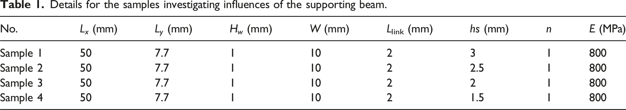
Details for the samples investigating influences of the supporting beam.
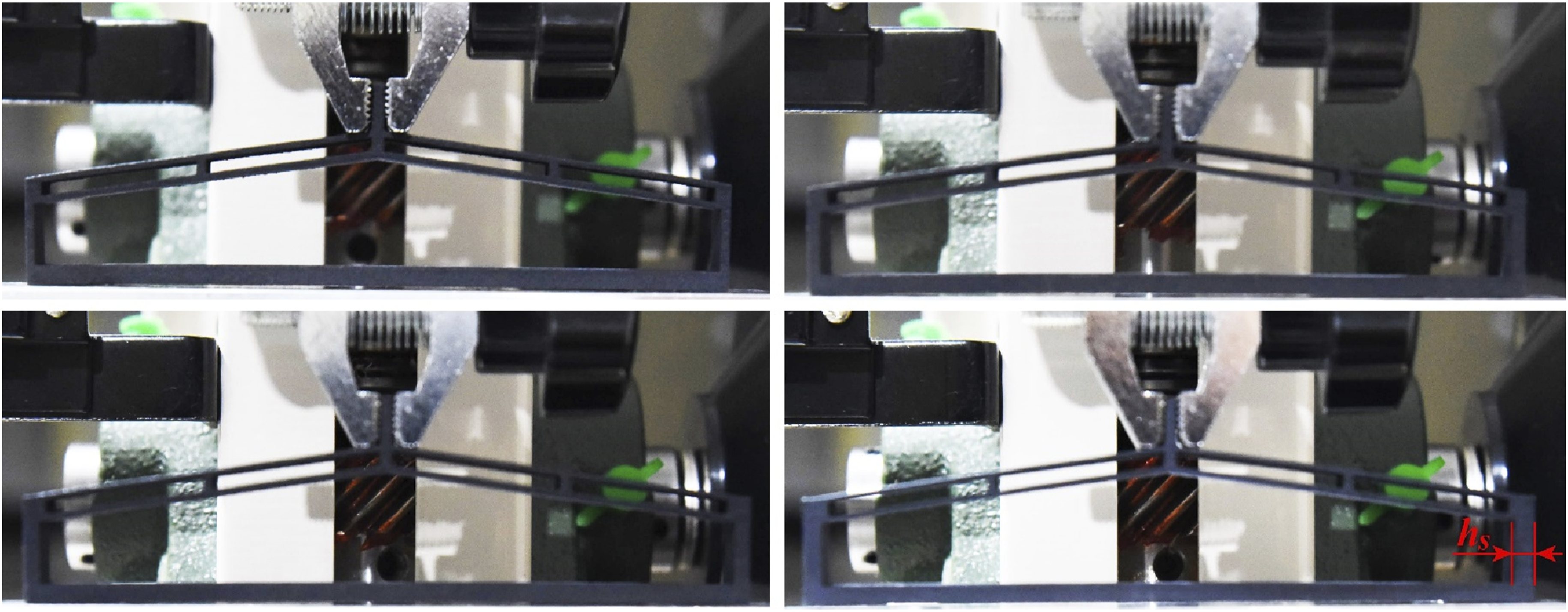
Experimental investigation on influences of the supporting beam.
Force-displacement curves of these structures are given in Figure 6. As shown in the figure, the plateau area in the force-displacement curve is observed in all of the samples regardless of the stiffness of the horizontal axial restraint. On the other hand, it is clear that a reduced stiffness of the horizontal restraint leads to a more gradual shift from initial stiffness of the structure to the QZS branch. This is understandable. As the shown in Figure 4, the plateau area can happen when negative stiffness phenomenon occurs in the snapping beam. However, the possible trajectory of the connected bistable beam is affected by stiffness of the horizontal restraint, which, in turn, determines the range of the deformation which shows the QZS. Comparisons of the predicted behavior of the structure with different supporting beams with the experimental data.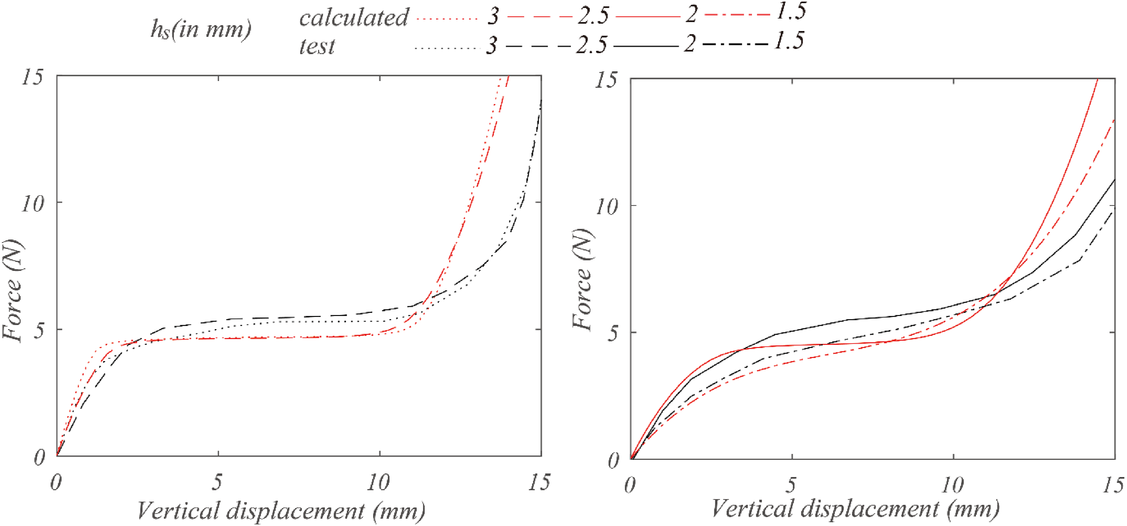
Figure 7 further investigates performance of the structure composed by non-identical bistable beams connected together. Portions of the horizontal length of the beams connected are marked in the figure for comparisons. The other details were similar to presented in Figure 5. It is achieved by adjusting location of the rigid link, thus providing different lengths for the left and right bistable beams. L
y
of the beams were also designed to be different as noted in the figure. The other geometric details are similar with the specimens shown in Table 1. A very rigid support was provided for the beam. The figure shows that the plateau branch can only be observed when lengths of the two beams are close to each other. When the ratios of the length of the connected beams are 5:7 or 1:2, a branch with significant negative stiffness can be observed. This phenomenon is indicated by deductions made in previous section. Figure 8 shows the possible force-displacement trajectories of a bistable beam restrained by a significantly longer but weaker beam with similar thickness. As shown the figure, this configuration does not allow a trajectory with low tangential stiffness. Experimental investigation on behavior of the structure with different bistable beams. Possible trajectory of the force-displacement curve when L
x1
:L
x2
= 5:7.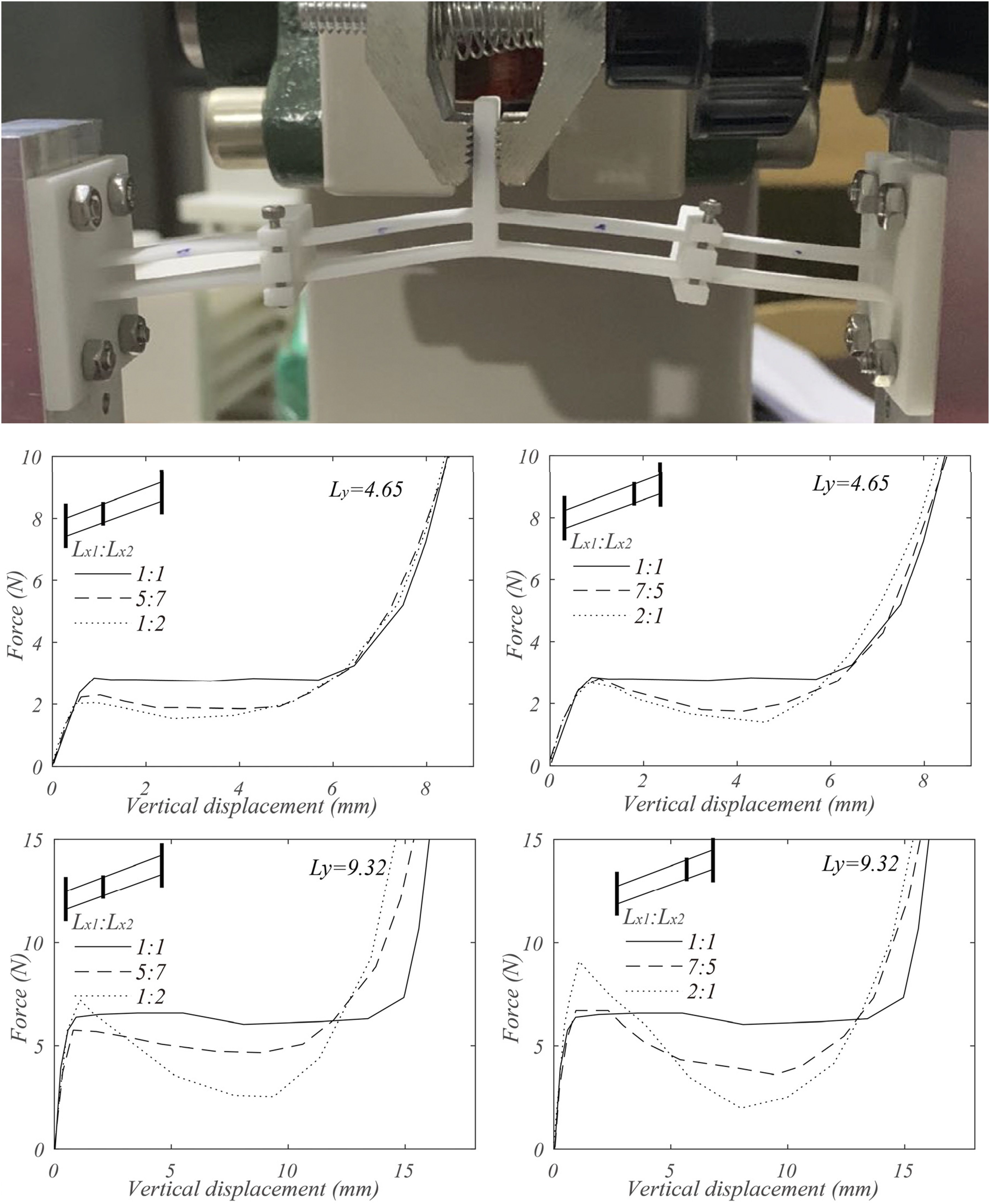
Numerical model and parametric study
Numerical model
The proposed structure has numerous stable positions adjacent to its symmetric deformation mode, which makes it very difficult to be analyzed by conventional FE method. However, the chained constrained beam model proposed by Ma and Chen (2016) 35 was found to be able to approximate its behavior.
The model is based on eqs. (4)–(8). The model divides the original beam into branches the behavior of which can be approximated by eq. (3). Overall behavior of the beam can therefore be solved by equilibrium of the divided beams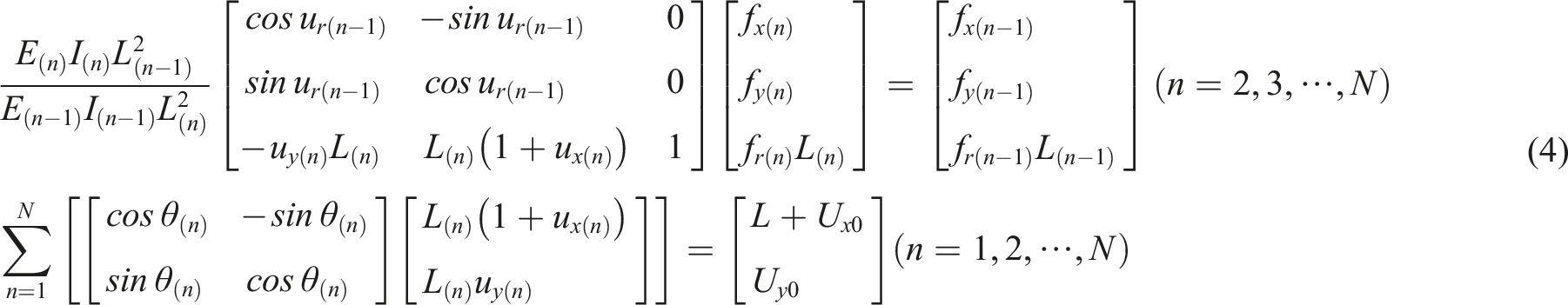
For each branch, eq. (6) has to be satisfied
The authors derived an explicit method for calculating extreme strain of the beam based on eq. (7)
For the structure being considered, it is assumed that links connecting the parallel beams are truly rigid, which gives eq. (8) as bound condition for the chained constrained beams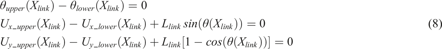
In the equation, θ upper (X link ), U x_upper (X link ), U y_upper (X link ), θ lower (X link ), U x_lower (X link ), U y_ lower (X link ) are the angle of rotation, deformation in the global X and Y direction for the upper and lower parallel beam at location of the rigid link, respectively. L link is length of the rigid link. Together with the compatibility, force equilibrium equations and the flexible boundary condition of the horizontal support, the unknowns introduced by the equations are similar with the number of the additional equations to be solved. The test results presented in Figure 6 are used for validation of the results of the model. As shown in Figure 6, the predicted results of the model matched the experimental results well.
Numerical parametric study
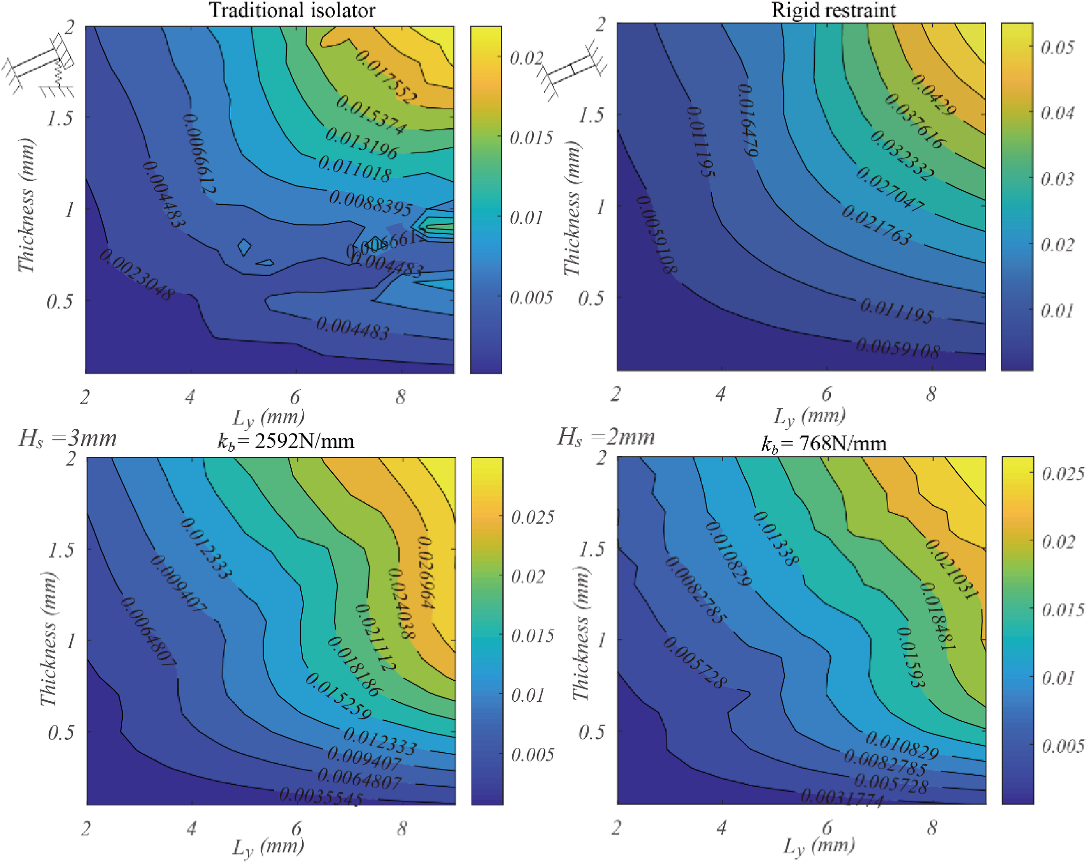
An extended numerical parametric study was conducted using the model investigating behavior of the structure affected by rigidity of the horizontal restraint. For the study, L x is assumed to be 50 mm. W is 50 mm. H w is 1 mm and E is assumed to be 800 MPa. Performance of the structure under a rigid restraint is also given in the figure for comparison. Additionally, performance of a traditional isolator based on matching of positive and negative stiffness is also included.
The minimal stiffness associated with the structure is shown in Figure 9. For the traditional isolator, negative stiffness is expected generated by the bistable beam as shown in the figure. This negative stiffness is to be matched with a linear spring with positive stiffness. For the isolators based on the integrated structure, on the other hand, it is clear that a minimal stiffness close to 0 is commonly observed with a large enough L
y
. This is in consistent with previous experimental observations. With a flexible restraint, the combination of L
y
and t which can generate the QZS is reduced. However, the QZS phenomenon is still commonly observed. Figure 10 shows the loading capacity corresponding to the QZS of the isolators. For the traditional QZS isolator, contribution of the linear spring is considered. The figure shows that with similar geometric details, the loading capacity of the isolator based on the proposed structure is comparable with that based on a single bistable beam. With the reduction of the thickness of the supporting beam, the strengths are slightly reduced. However, with L
y
and t combinations that can generate the QZS, the reduction is not significant. Comparison of the minimal stiffness for the parametric study. Comparison of the loading capacity of QZS isolators for the parametric study.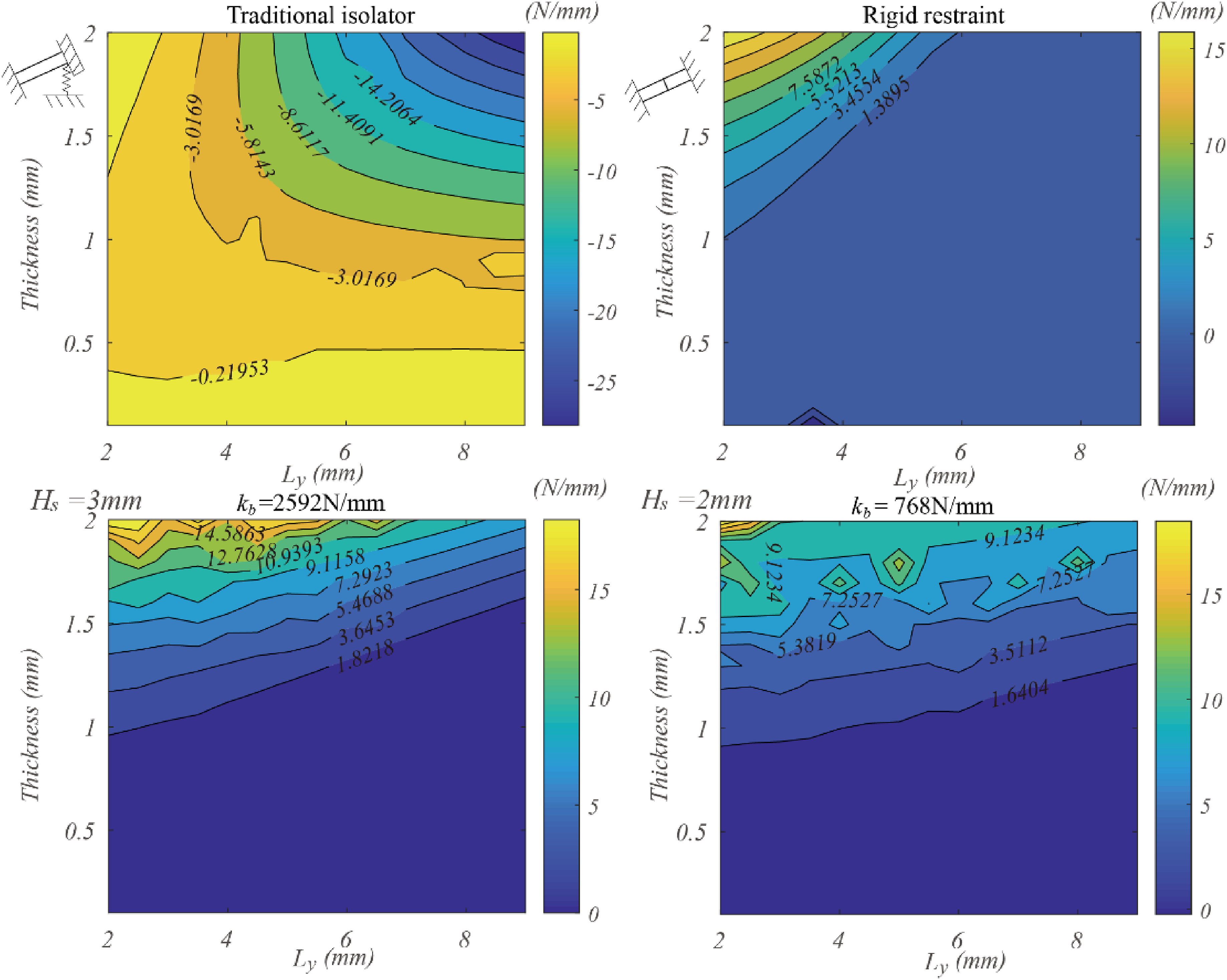
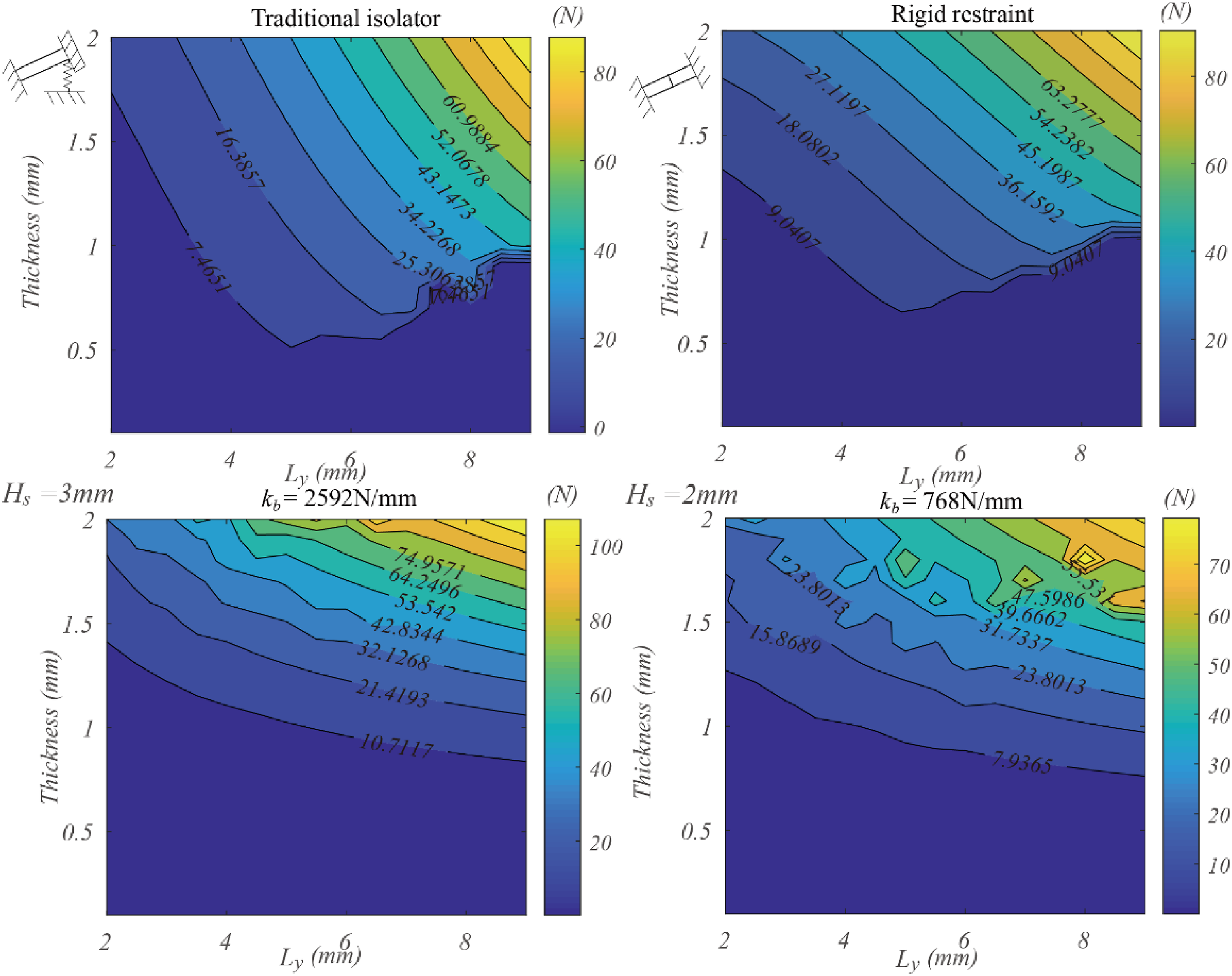
Figure 11 shows the range of the displacement corresponding to the QZS phenomenon. The value presented is calculated as the deformation between 90% and 110% of the force presented in Figure 9 in the force-displacement curve. As the figure shows, QZS isolator based on the proposed structure can have better range of deformation corresponds to the QZS compared with the isolator based on matching of positive and negative stiffness. Also, a reduced lateral support leads to significant reduced length of the plateau. Figure 12 summarizes the extreme strain observed for the structure when it is imposed with a vertical displacement of L
y
. Compared with the isolator based on a single bistable beam, the extreme strain of the isolator based on the proposed structure is significantly reduced. Considering the other performance of the isolator is comparable and the extreme strains often controls the design of bistable structures, it is clear that the isolator based on proposed structure can have better performance compared with conventional QZS isolators. With the reduction of the thickness of the supporting beam, the extreme strain can be further reduced. Comparison of the displacement corresponding to the QZS for the parametric study. Comparison of the extreme strain for the parametric study.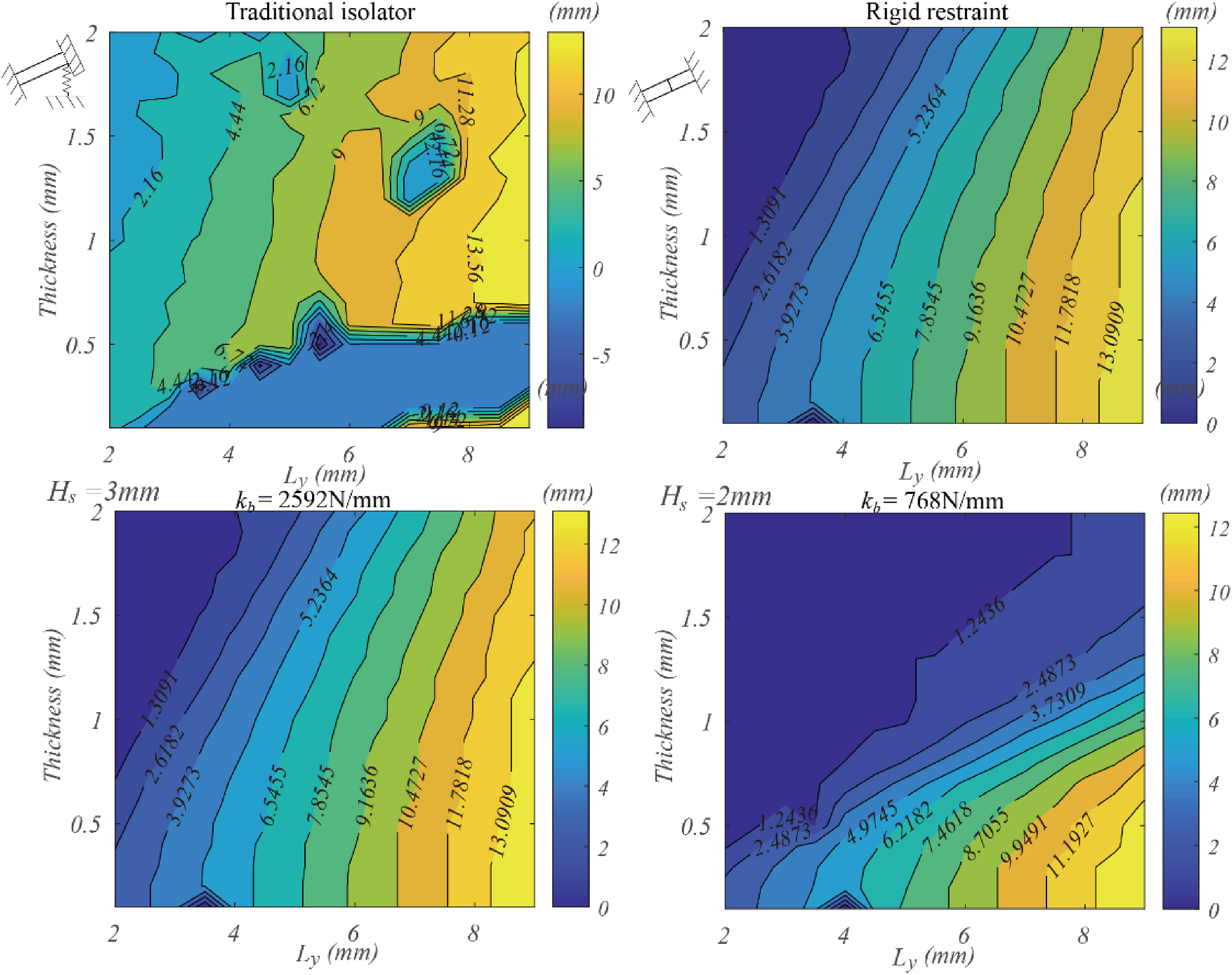
Light-weighted QZS device based on the proposed structure
Details for the isolator samples tests.
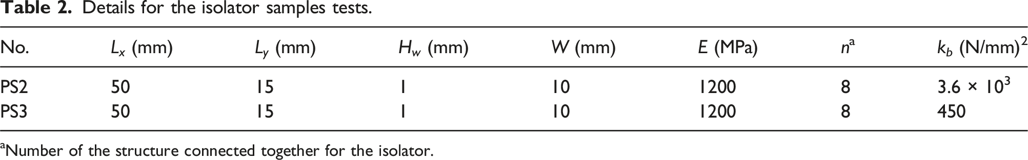
aNumber of the structure connected together for the isolator.
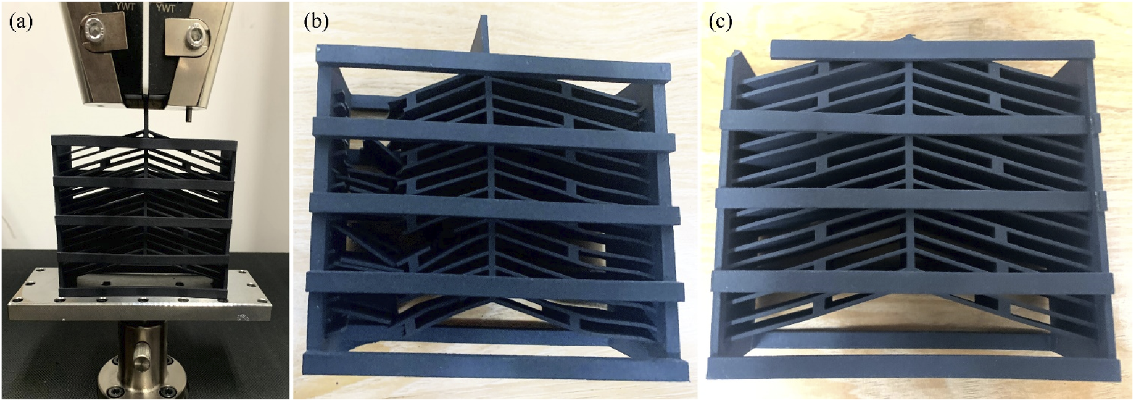
Test and failure of isolator sample (a) test setup, (b) failure of PS2, and (c) failure of PS3.
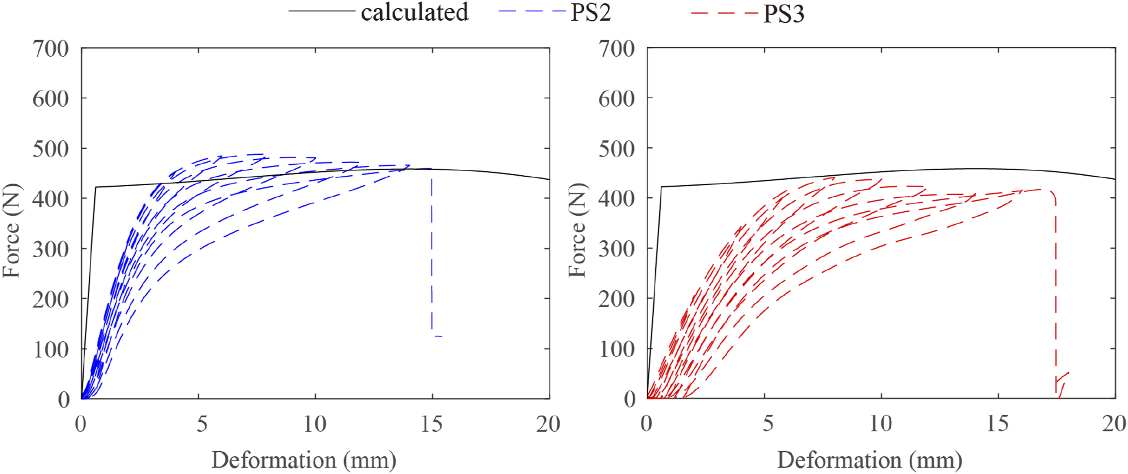
Force-displacement behavior of PS2 and PS3.
Summary and conclusions
This paper investigates a type of QZS device based on inclined beam on flexible support. The quasi-zero stiffness of the isolator is generated by nonlinear axial interaction of the beam and is independent of the stiffness of the horizontal restraint. The mechanism to generate the quasi-zero stiffness is discussed, and a numerical model is developed for predicting behavior of the structure which is validated by a series of tests. The following conclusions are highlighted: • A consistent force plateau exists in force-displacement curves of inclined bistable beams connected in series with a flexible horizontal restraint. Stiffness of the restraint only affect length of the force plateau but strength and secant stiffness of the structure corresponding to the quasi-zero stiffness is rather independent of it. • A series of tests were conducted regarding performance of QZS isolator based on the investigated structure. The results show that strong and light-weighted QZS isolators can be designed taking advantage of the less strict boundary condition required by the structure. An isolator composed of nylon material with a dimension of 50 mm * 110 mm * 85 mm was shown to have a plateau force around 400 N.36–44
Footnotes
Declaration of conflicting interests
The author(s) declared no potential conflicts of interest with respect to the research, authorship, and/or publication of this article.
Funding
The author(s) disclosed receipt of the following financial support for the research, authorship, and/or publication of this article: This study was funded by the National Natural Science Foundation of China (52108275) and National Key R&D Program of China (Grant No. 2020YFB03502).