
Abstract
Based on the significant geometric nonlinearity associated with large deformations in beams, this paper presents the design of a buckling-type quasi-zero stiffness (BQZS) isolator using slender beams with positive and negative stiffness. This design achieves a characteristic output of nonlinear load-bearing combined with linear stiffness. The elliptic integral method is employed to solve the mechanical equations of the large deformation beams. Through numerical simulations and theoretical calculations, the mechanical properties of the large deformation beams are obtained. A prototype was designed for validation, and its manufacturing and experimental studies are presented. The results demonstrate that the designed BQZS isolator effectively attenuates the system’s vibration response, achieving a 95% reduction at 5 Hz vibration excitation. Additionally, the natural frequency of the isolator with BQZS is less than 1 Hz.
Introduction and background
The rapid advancements in precision engineering and measurement technologies have placed increasingly rigorous demands on ultra-low-frequency vibration isolation techniques. Traditional linear isolators, while generally effective in achieving isolation through reduced stiffness, often face issues such as diminished load-bearing capacity and pronounced static deformation, which can compromise system stability. To address this challenge, researchers have proposed quasi-zero stiffness (QZS) isolators, which leverage nonlinear designs characterized by high static stiffness and low dynamic stiffness. However, achieving QZS in practice remains complex, as it requires precise balancing of positive and negative stiffness elements, adding significant challenges to the design and implementation of effective QZS isolators. This intricate design approach, though demanding, offers a promising solution for stable and efficient isolation performance.
QZS isolators of diverse configurations have garnered extensive attention and investigation. Yang 1 investigated a heavy-load-bearing QZS vibration isolator consisting of three compression springs. Guo 2 proposed a reusable bidirectional quasi-zero stiffness metamaterial (BQZS-MM) with quasi-zero stiffness zones under compressive and tensile loads. The BQZS-MM is characterized by the parallel connection of positive stiffness components and negative stiffness components to generate the QZS. Zhang 3 investigated the bursting oscillations in a vibration isolation system with quasi-zero stiffness to improve the efficiency and reliability. Zeng 4 proposed a novel limb-inspired bionic structure generate negative stiffness and designed a new quasi-zero stiffness isolator via torsion springs, distinguishing from the exiting tension spring structures in the literature. Lian 5 presented a QZS vibration isolator with adjustable nonlinear stiffness. Zhao 6 presented an innovative design of the quasi-zero stiffness isolator with three pairs of oblique springs. Additionally, recent developments have explored QZS isolators based on metamaterials and origami structures. Liu 7 proposed a kind of quasi-zero stiffness QZS metamaterial constructed from a series of Kresling-pattern origami-inspired structures, whose simple topology with reasonable design parameters can obtain the expected QZS features. Hamzehei 8 discussed advances in soft metamaterials with QZS properties aimed at isolating vibrations in various engineering contexts, particularly effective for mitigating low-frequency oscillations.
Traditionally, QZS isolators employ linear springs to design positive and negative stiffness elements. In recent years, scholars 9 have employed nonlinear structures to design QZS isolators. Virgin 10 utilized Euler beams to achieve low-frequency vibration isolation. Despite the high axial stiffness of Euler beams before buckling, their stiffness significantly decreases after buckling, which may affect system stability in practical applications. Chao et al. 11 proposed a QZS isolator based on Euler beams, replacing the positive stiffness elements in traditional three-spring systems with Euler beams to achieve higher load-bearing capacity and lower frequency. Zhang et al. 12 studied a structure consisting of parallel inclined beams coupled with rigid bars, which, compared to traditional bistable structures comprising bending beams and inclined beams, exhibited higher load-bearing capacity. Huang et al. 13 proposed a QZS isolator utilizing Euler buckling beams as negative stiffness and compared it with linear isolators. Liu et al. 14 designed a nonlinear isolator using electromagnetic negative stiffness elements, comprising two electromagnets and a magneto-rheological elastomer, adjusting drive currents based on displacement data to precisely control system stiffness in real-time. Shuai et al. 15 designed a QZS isolator utilizing air springs to provide negative stiffness, effectively mitigating the effects of friction. Prakash 16 proposed an improved formulation of horizontal shear behavior of the unbonded fiber-reinforced elastomeric isolators, which predicts both the pre-rollover and post-rollover behavior considering the effect of the vertical load. Ji et al. 17 presented a review of metamaterials and origami-based structures as well as their applications to vibration control, highlighting that origami achieves multi-stability and nonlinear stiffness through geometric transformations, making it suitable for vibration isolation. The nonlinear characteristics of the force-displacement response in origami structures can be utilized to achieve QZS design.
QZS isolators designed based on linear elements require a trade-off between load-bearing capacity and stiffness. Typically, QZS isolators utilize linear elements for positive stiffness, requiring sufficiently high stiffness to meet load-bearing and deformation requirements. However, this necessitates the corresponding substructures to impart a large negative stiffness to counteract positive stiffness, thereby achieving QZS of the system. It is evident that utilizing two structures with high stiffness to compose a well-performing QZS system poses considerable challenges. On the other hand, research on Euler beams mainly focused on boundary conditions with hinged support at both ends, introducing friction and lower system stability. Additionally, most studies continued to combine Euler beams with linear springs to design QZS isolators, which introduce stiffness nonlinearity. This approach results in a more restricted QZS range and can lead to amplitude amplification and jumps under large external excitations.
Building on the preceding analysis, this paper proposes a BQZS isolator, wherein both positive and negative stiffness structures are composed of slender beam elements with fixed boundary constraints, presenting an integrated configuration unaffected by frictional forces. The slender beams with positive stiffness exhibit high load-bearing capacity and stiffness before buckling, whereas after buckling, their stiffness significantly decreases and remains relatively unchanged. The slender beams with negative stiffness exhibit lower and relatively constant stiffness after buckling. The combination of these two elements achieves nonlinear load-bearing capacity and linear stiffness of the BQZS isolator. A mathematical model of positive and negative stiffness slender beams is established, and the elliptic integral method is employed to solve the nonlinear stiffness characteristics of slender beams. A prototype is designed to conduct experimental verification. The proposed BQZS would be beneficial for researchers, such as those studying piping supports for seismic response control. 18
Mechanical model of beams
The model of the BQZS isolator, depicted in Figure 1(a), comprises a rigid mass block m, inclined negative stiffness slender beams, and vertical positive stiffness slender beams. Initially, the negative stiffness beams are straight with a length of L1 and an inclination angle β, while the positive stiffness slender beams are vertical with a length of L2. Upon the application of load m, the slender beams experience buckling deformation, as shown in Figure 1(b). The slender beams are constrained by clamped boundary conditions. BQZS vibration isolator. (a) Initial state and (b) after deformation.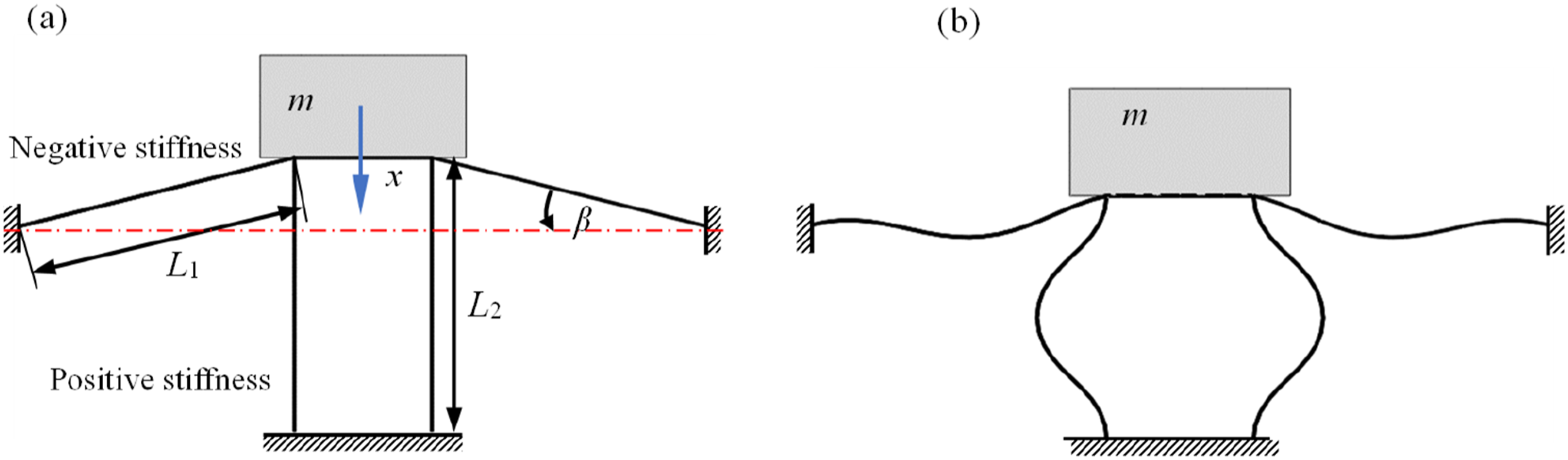
Model of positive stiffness beams
To simplify the analysis, the positive and negative stiffness slender beams are analyzed separately. The model of the positive stiffness slender beam is shown in Figure 2. In practical engineering applications, slender beams often exhibit slight initial deformations. According to the principle of minimum potential energy, the buckling deformation occurs in the lower-order mode, avoiding higher-order buckling modes. To approximate the realistic buckling deformation, a small perturbative force 2P is applied vertically at the midpoint of the beam. Positive stiffness slender beam model.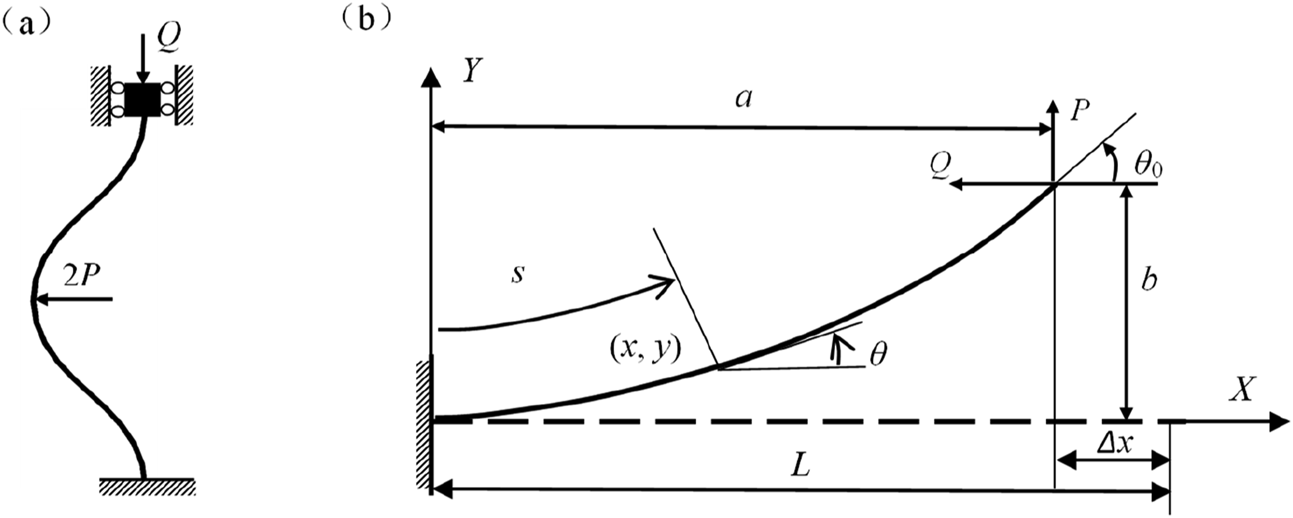
Due to the symmetry of the deformation in the positive stiffness slender beam and the anti-symmetry of its half structure, one-quarter of the entire beam is analyzed. Since the bending moment at the inflection point is zero, this quarter-beam structure can be modeled as a cantilever beam subjected to a concentrated load at the free end, as depicted in Figure 2(b).
Model of negative stiffness beams
Figure 3 illustrates the model of a slender beam with negative stiffness. Initially, the slender beam forms an angle β with the horizontal direction, and its end B moves vertically downwards. Using A as the origin, a coordinate system is established with the initial direction of the beam’s length as the x-axis. During the deformation process of the beam, the end rotation angle remains constant and is maintained at zero. Negative stiffness beam model.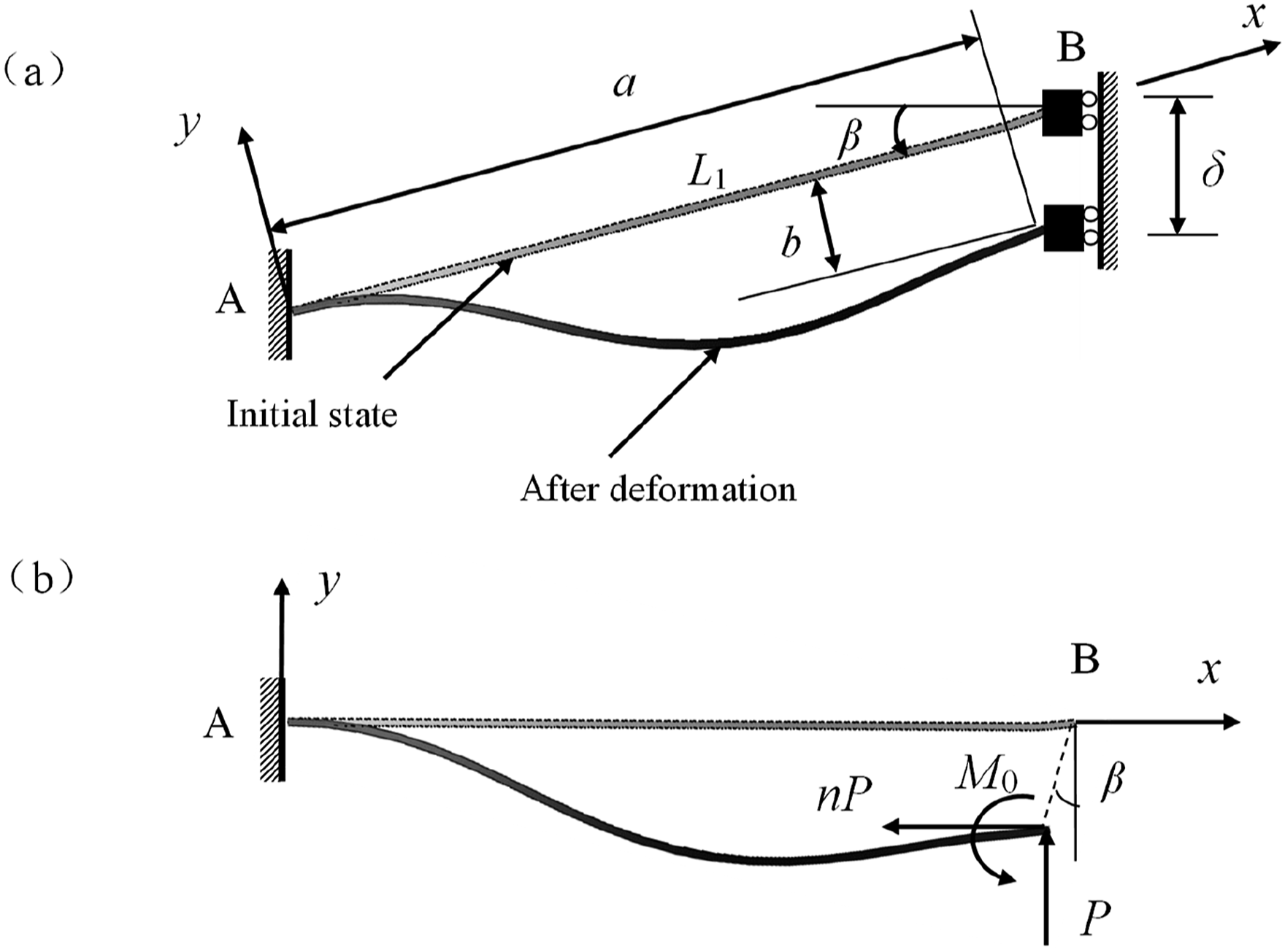
Analysis of positive and negative stiffness theory
Among the various methods for calculating large deformations of slender beams, the elliptic integral method offers the highest accuracy in solution. Due to its analytical expression, it achieves extremely high computational efficiency. Therefore, this paper employs the elliptic integral method to solve the nonlinear deformation of slender beams and establishes a more generalized model to describe the deformation of beams with positive and negative stiffness. Figure 4 illustrates the general deformation of the beam under the combined action of concentrated force and moment at the end. A coordinate system is established with the fixed end of the beam as the origin, and the initial direction of the beam before deformation is taken as the X-axis. The end force ηP can be decomposed into p and nP, represented by the following equation: Slender beam with concentrated force and bending moment at the end.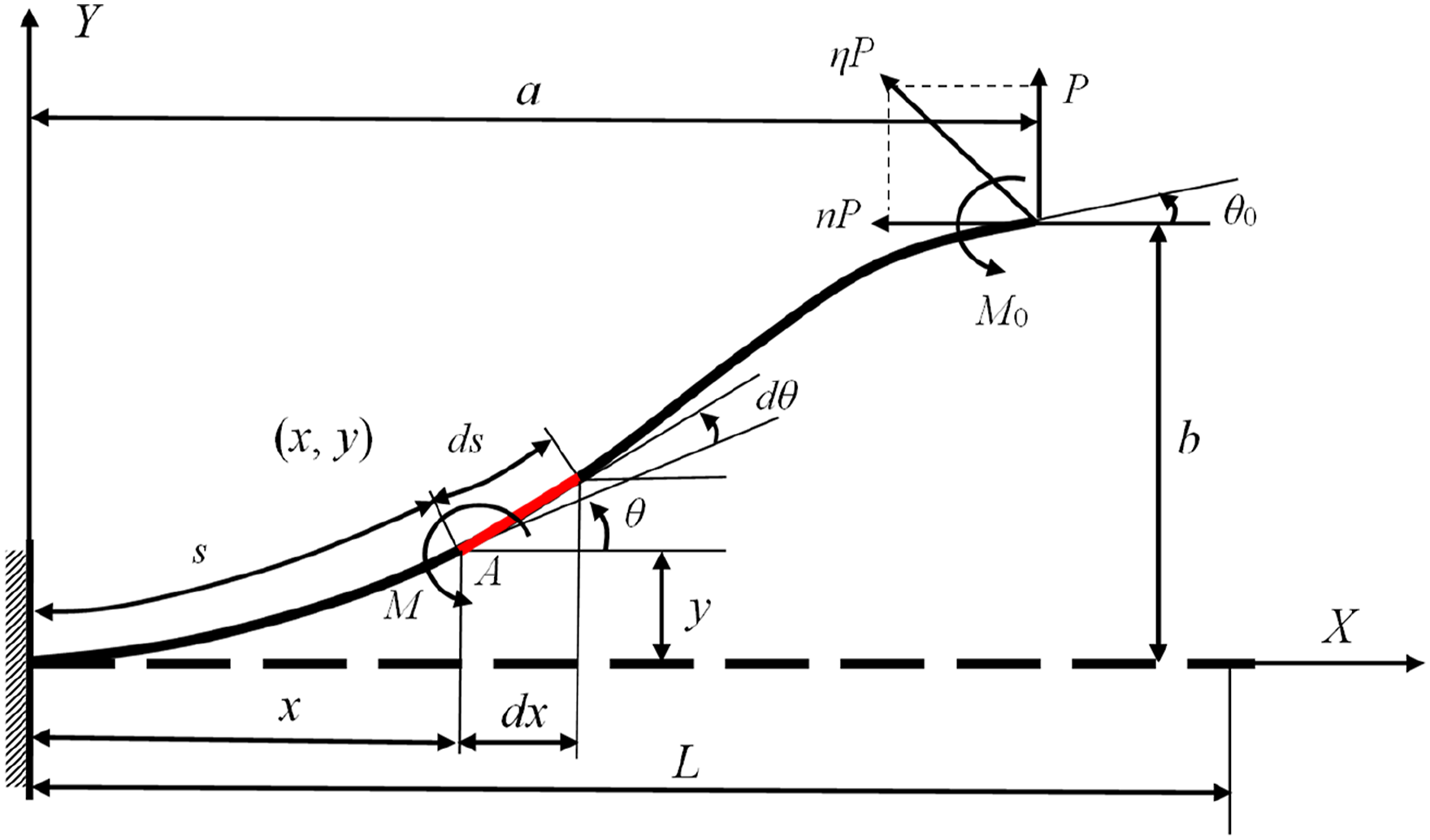

According to Bernoulli-Euler beam theory, the bending moment M at any point A (x, y) on the beam is proportional to the curvature K at that point:

Here, M represents the bending moment at point A, E is the Young’s modulus, I is the moment of inertia of the beam’s cross-section, and K is the curvature at point A. θ is the angle between the tangent at point (x, y) and the X-axis, and dθ/ds is the curvature at that point. It is assumed that the total length L of the beam remains constant.
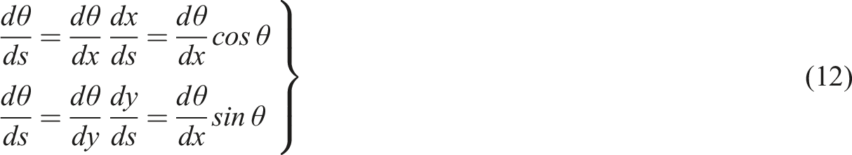
Taking the derivative of equation (2) with respect to s, and considering dx, dy, and ds as infinitesimal quantities, we have dx/ds = cosθ and dy/ds = sinθ. Consequently,


Substituting equation (2) into equation (4), we obtain

Substituting equation (5) into equation (3), separating variables and integrating, we obtain


Substituting equation (7) into equation (6) yields the general expression for the curvature K as

The symbols chosen in equation (8) are as follows: positive for concave deformation of the beam and negative for convex deformation. For brevity, equation (8) is denoted as equation (9):


Defining the load factor

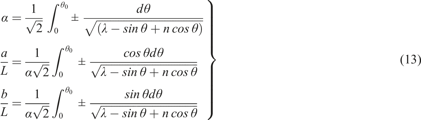
To determine the position of the free end, a transformation of
Combining with equation (9), we derive:
Since the process for solving elliptic integrals has been detailed in literature, 13 this paper does not undertake a detailed derivation but rather presents the elliptic integral solution for slender beams with positive and negative stiffness directly.
Elliptic integral solution
Solution for beams with positive stiffness
The quarter-simplified model of a beam with positive stiffness is depicted in Figure 2(b), where the beam’s rotation angle θ varies monotonically with s without inflection points. Equation (14) represents the elliptic integral solution corresponding to beams with positive stiffness:
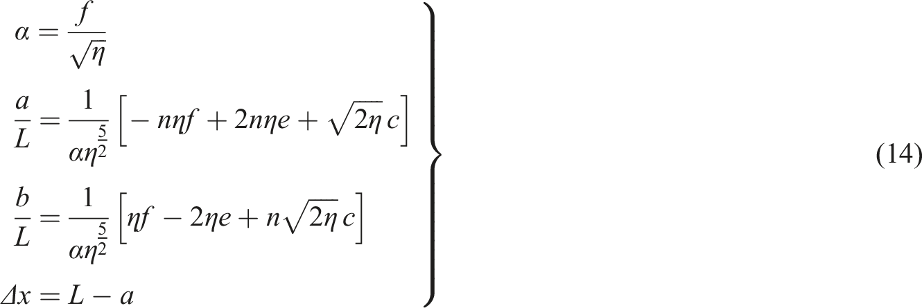
Given load parameters n, p, and initial deformation parameter θ 0 , numerical iteration using equation (14) allows for the determination of θ 0 , subsequently enabling the calculation of the end position (a, b). This process ultimately establishes the force-displacement relationship for beams with positive stiffness.
Elliptic integral solution for beams with negative stiffness
The model for a beam with negative stiffness is illustrated in Figure 3(b), which shows two inflection points along the beam. The elliptic integral solution corresponding to a beam with negative stiffness is given by equation (15).
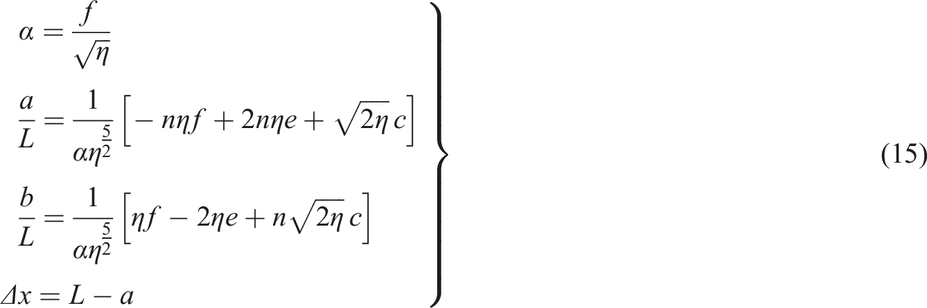
Here


Due to the fact that the end rotation angle θ
0
of the beam with negative stiffness remains constant and equal to zero during deformation, and that there are two inflection points, equation (15) can be simplified to equation (16).
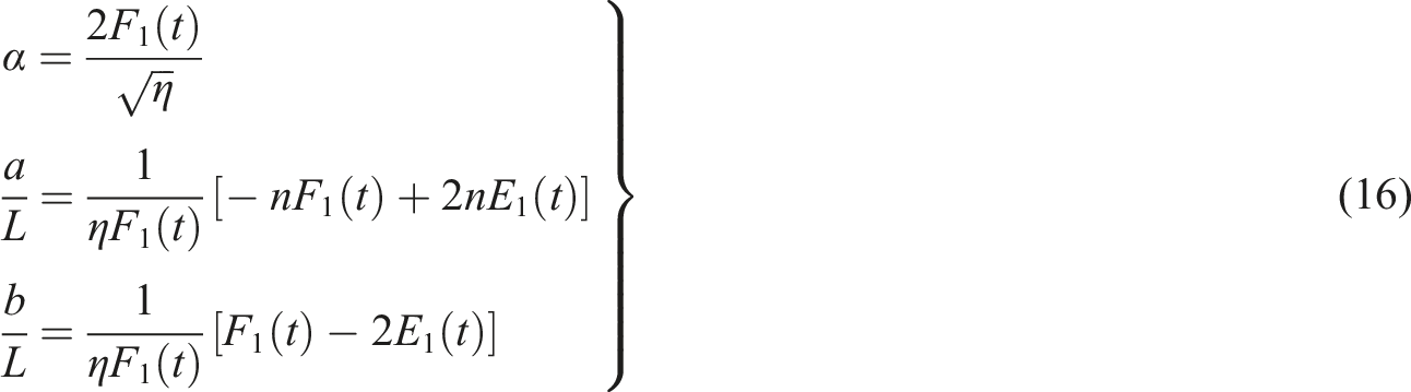
In Figure 3(b), the coordinates of point B can be expressed as:

Here, δ denotes the vertical downward displacement of point B. The vertical force F, along the coordinate axis, can be resolved into nP and P, yielding

Given the displacement δ, the coordinates a and b of the guided end point B can be obtained from equation (17). Substituting a and b into equation (16), κ and n can be iteratively determined using the complete elliptic integral solution, thereby establishing the beam’s force-displacement relationship.
Numerical simulation results
Based on the results of the theoretical analysis, the analytical expressions are obtained in this section, and the correctness of the theoretical analysis is verified by the finite element method.
Numerical calculation and simulation of positive stiffness beams
The simulation model is shown in Figure 2(a), the parameters of the positive stiffness beam are length L2 = 100 mm, width W2 = 10 mm, thickness T2 = 0.3 mm, and Young’s modulus E = 200 GPa, and the research content is the relationship between the vertical force Q and the vertical displacement ∆x of the beam under the action of small perturbation force 2P.
Figure 5 shows the numerical calculation results and finite element simulation results of the positive stiffness beam during the deformation process. It can be seen that the two are highly consistent, which verifies the correctness and accuracy of the elliptic integral method. In the initial stage of deformation, the bearing capacity of the beam increases rapidly. Compared to the linear stiffness element, the motion stroke is greatly reduced. When the deformation passes the nonlinear section, the force-displacement curve shows a linear change, indicating that the stiffness remains constant and its linear interval is large. Force-displacement curve of positive stiffness beam.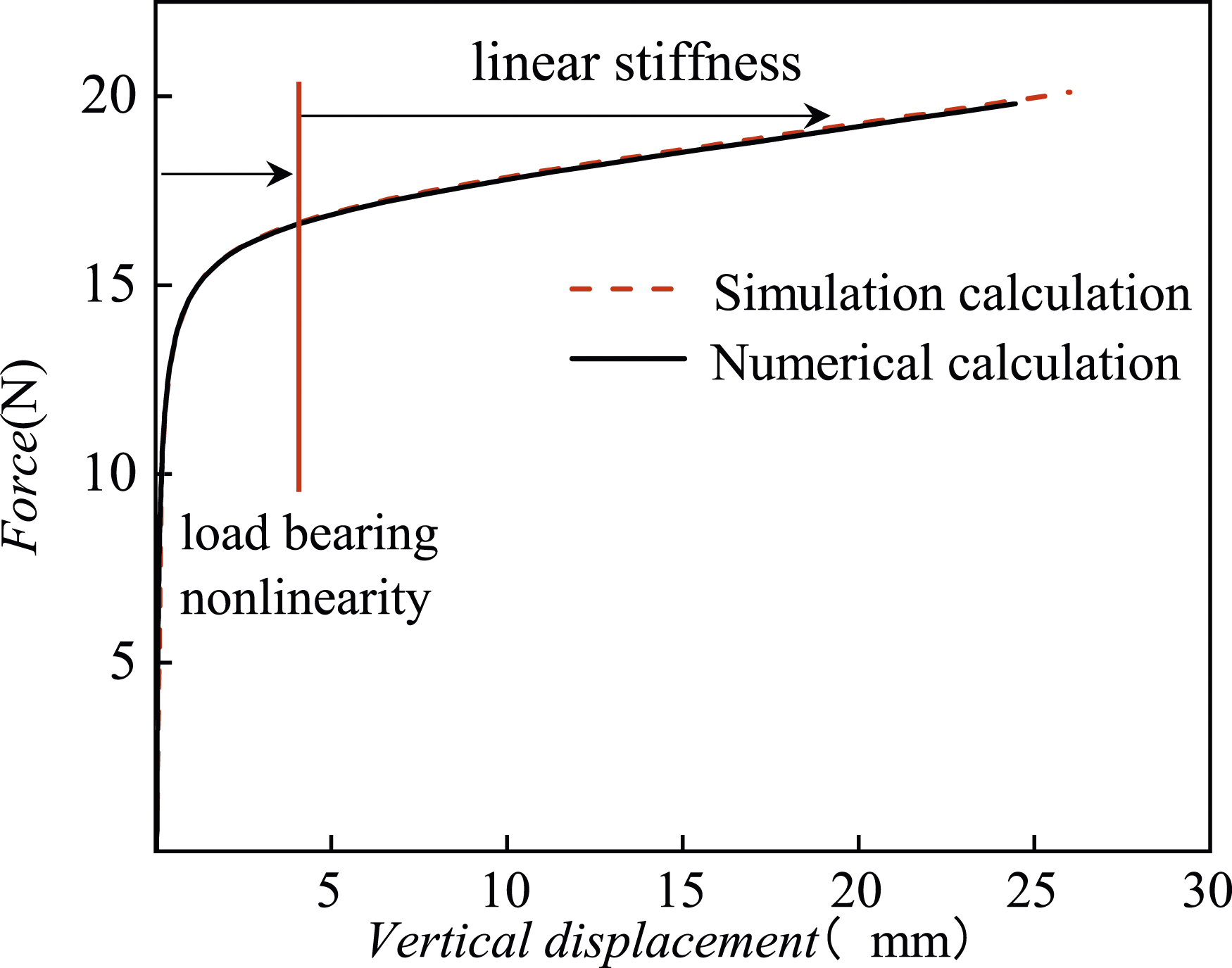
The positive stiffness beam exhibits nonlinearity in the bearing deformation section, which can reduce the motion stroke and increase the bearing capacity. In the working position, it displays linear characteristics, which can avoid the vibration amplification and amplitude jumps caused by nonlinear stiffness. These segmented linear and nonlinear characteristics make it highly suitable for the design of QZS isolators.
Numerical and simulation calculations of negative stiffness beams
The parameters corresponding to the negative stiffness structure composed of the double-piece diagonal beam in Figure 1 are as follows: Young’s modulus E = 200 GPa, length L1 = 90 mm, width W1 = 10 mm, thickness T1 = 0.25 mm, and initial angle β = 20°. Figure 6 shows the force-displacement relationship of the beam in the process of deformation obtained by numerical calculation and simulation calculation, which is in good agreement and verifies the correctness of the theoretical analysis. From the figure, it can be observed that the inclined beam reaches its maximum load-bearing capacity in the initial deformation stage and exhibits linear negative stiffness characteristics after buckling. This is highly compatible with the positive stiffness beam. Force-displacement relationship curve of negative stiffness beam.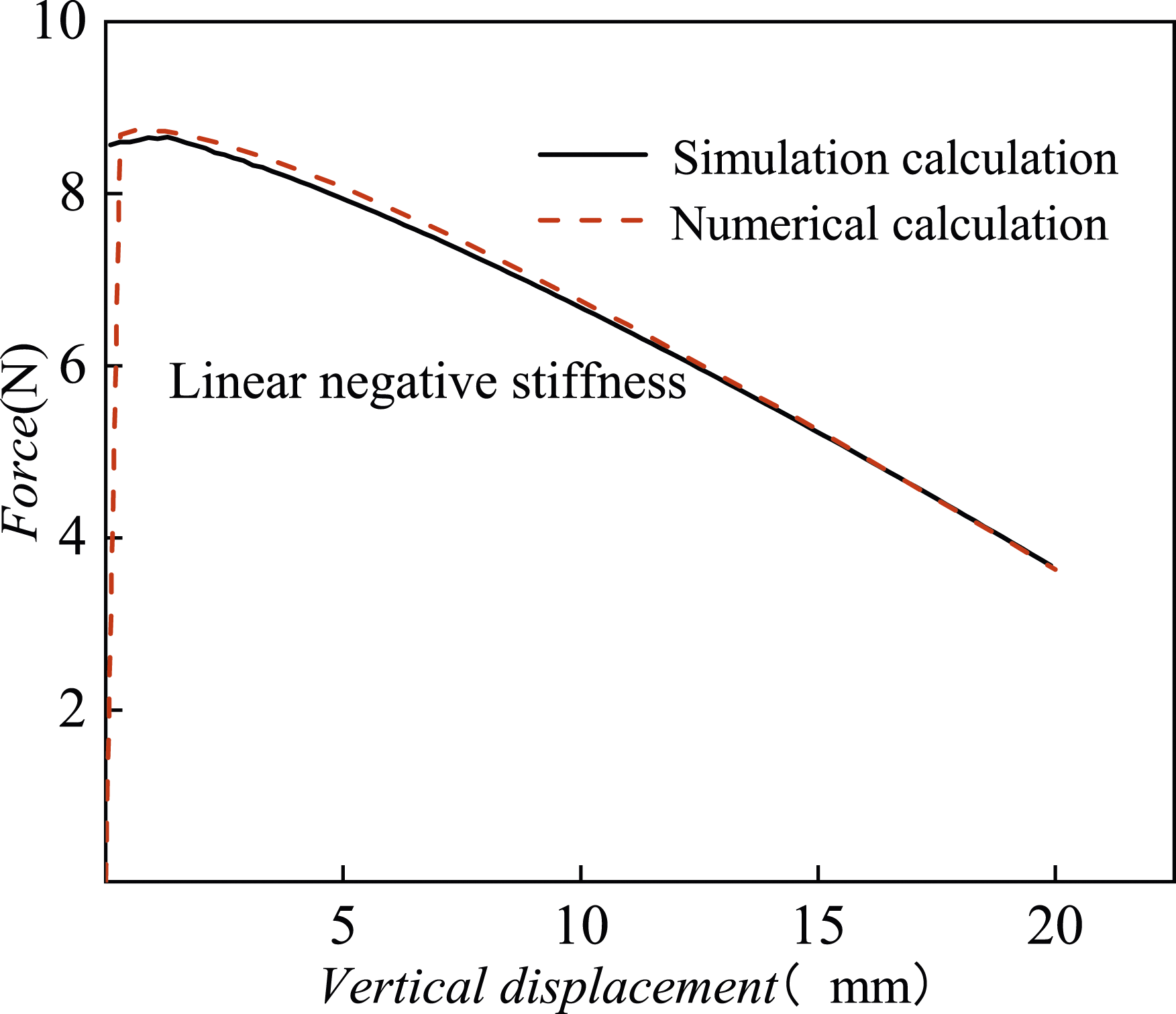
Figure 7 gives the variation trend of the vertical force F with the vertical displacement δ when taking different β values (from 5° to 20°, with an interval of 5°), it can be seen from the figure that the bearing capacity of the beam is different at different angles, but the stiffness basically does not change, and according to this characteristic of the negative stiffness beam, the inclination angle β of the negative stiffness beam can be adjusted to adapt to different loads, and the use range of BQZS isolator is broadened. Relationship between vertical force and displacement at different inclination angles.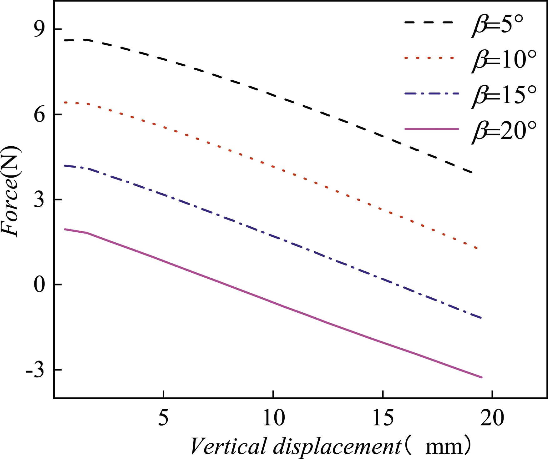
Parallel connection of positive and negative stiffness beams
Based on the analysis results of the positive and negative stiffness beams mentioned above, the BQZS structure shown in Figure 1 is analyzed. The structural parameters are as follows: length L1 = 100 mm, width W1 = 10 mm, and thickness T1 = 0.45 mm for the negative stiffness beam. The parameters of a positive stiffness beam are length L2 = 100 mm, width W2 = 10 mm, thickness T2 = 0.3 mm, and Young’s modulus of 200 GPa. Figure 8 shows the force-displacement curves of a negative stiffness beam with a BQZS structure at different tilt angles. It can be observed from the figure that the bearing capacity of BQZS structure increases rapidly during the initial deformation stage, and then the curve tends to be flat, meaning that the stiffness remains constant and the range of constant stiffness is large. Increasing the tilt angle of the negative stiffness beam increases the bearing capacity of BQZS structure but still maintains the QZS characteristics. Therefore, the tilt angle of the negative stiffness beam can be adjusted to adapt to different loads. When the tilt angle of the negative stiffness beam is 20°, the load of the quasi-zero stiffness structure is m = 6 kg, and its stiffness is k = 96 N/m. According to this, the vertical natural frequency of the quasi-zero stiffness structure can be obtained as 0.6 Hz. Force-displacement curves of quasi-zero stiffness structures under different inclination angles.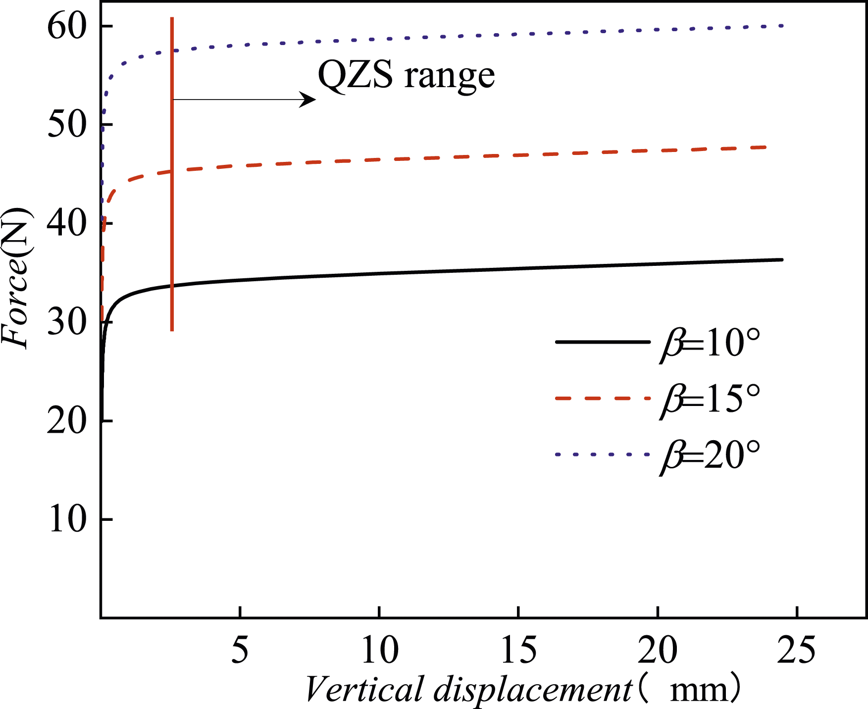
Simulation calculation of prototype
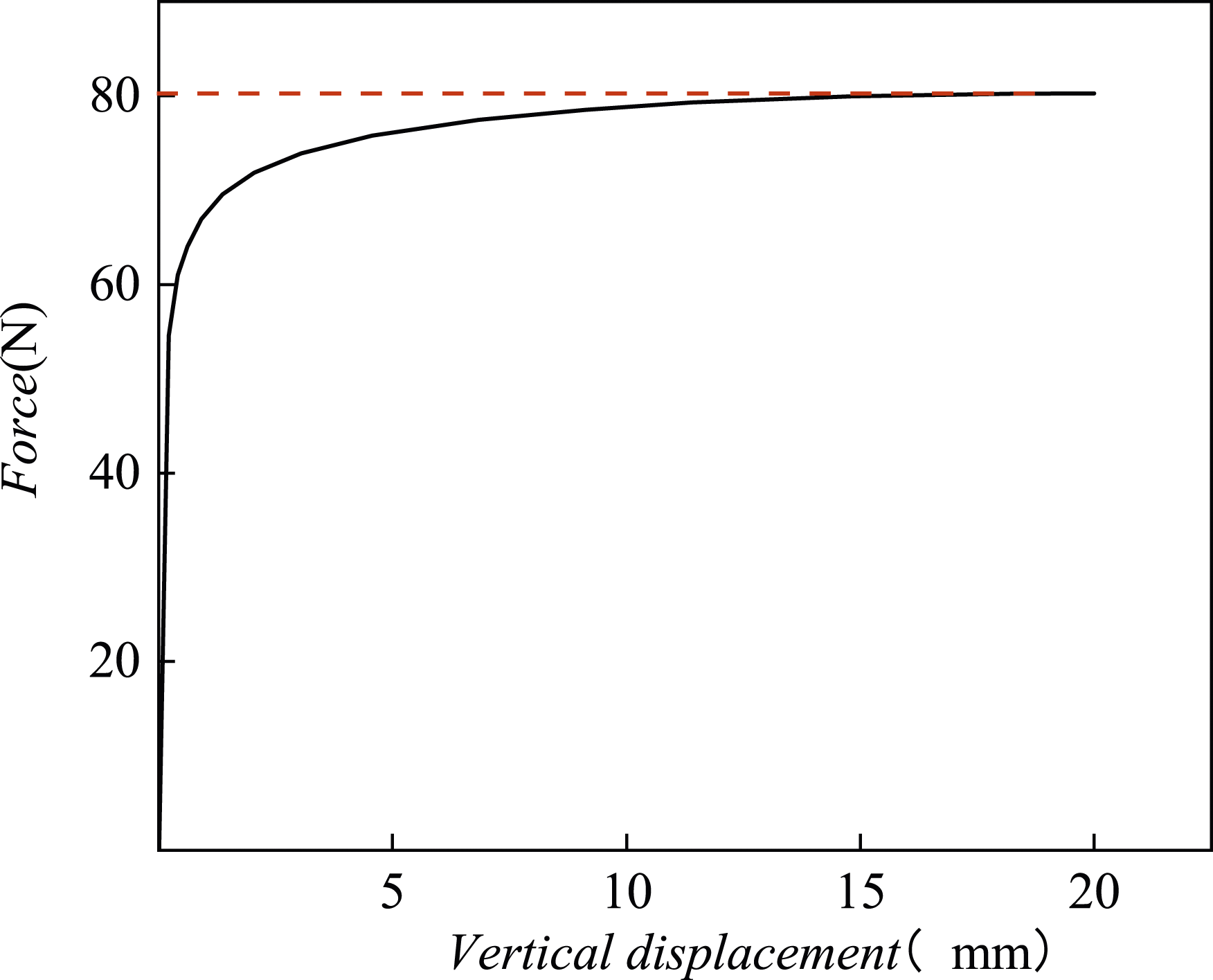
The simulation model of the prototype is shown in Figure 9. It includes 12 positive stiffness beams with dimensions of 100 mm in length, 10 mm in width, and 0.2 mm in thickness, and 6 negative stiffness beams with dimensions of 100 mm in length, 10 mm in width, and 0.3 mm in thickness. The ends of the slender beams are fixed and constrained. First, a vertical force-displacement curve is obtained through simulation, as shown in Figure 10. The load mass of the structure is 8 kg. Under this load, the vertical mode of the system is calculated, revealing a frequency of 0.6 Hz. Based on the modal calculation results, a frequency response analysis is performed to stimulate the accelerometer of the vibration isolator foundation. The sweep frequency range is 0.1 Hz to 10 Hz. The acceleration transfer function curve (black solid line) is shown in Figure 11. A resonance peak is observed at 0.6 Hz, consistent with the modal calculation results. When the frequency is greater than 0.9 Hz, the transfer rate is less than 1. Therefore, the initial vibration isolation frequency of the system is 0.9 Hz, and the corresponding transfer coefficient at an excitation frequency of 5 Hz is 0.017, indicating that the vibration isolator can attenuate 98% of the excitation at 5 Hz. Finite element model. Vertical force-displacement curve. Acceleration transfer function.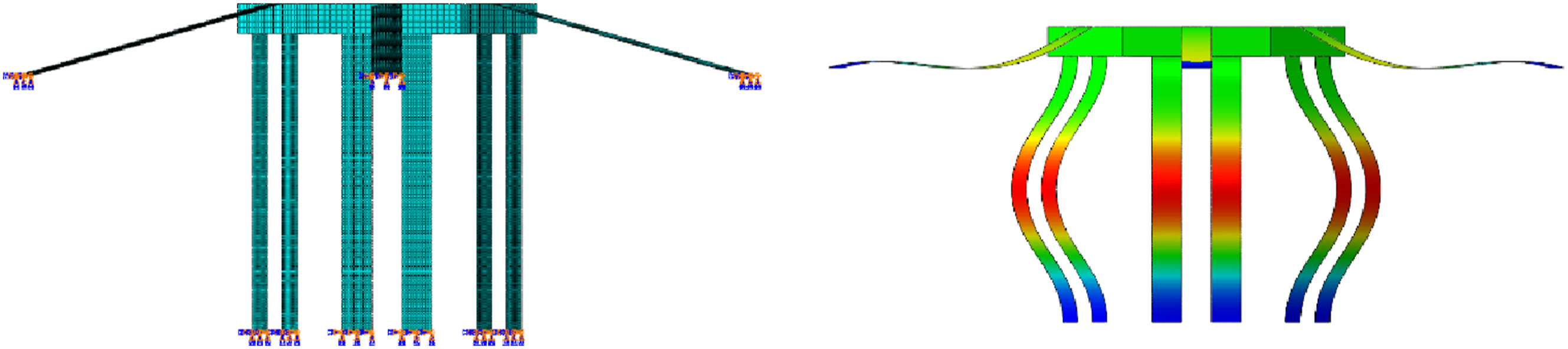
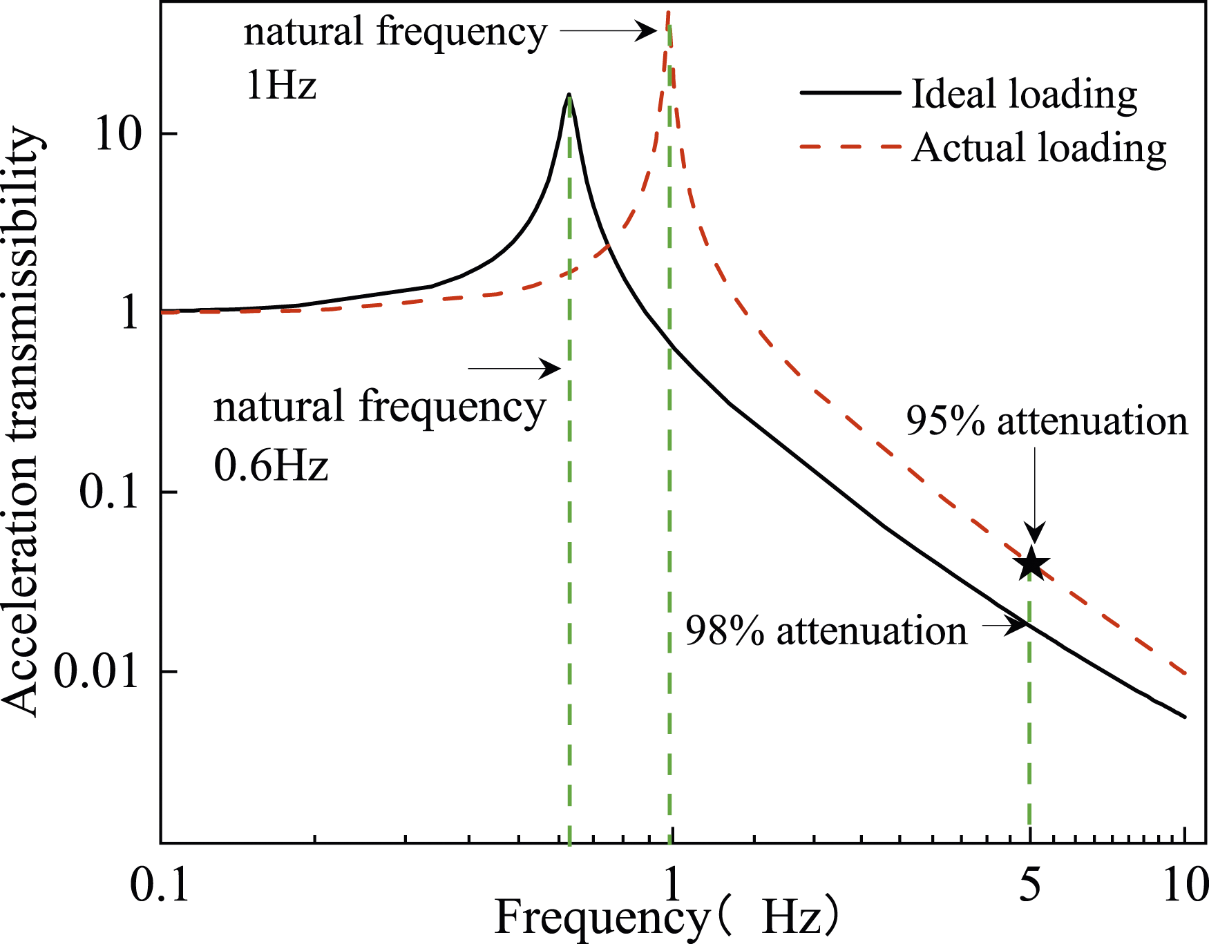
Given the need to address system stability in practical applications, the scenario of non-ideal loading is considered. Specifically, an ideal load of 79N and an actual load of 78N are examined. Figure 11 (red dashed line) presents the transfer rate curve under non-ideal loading. It can be observed that when the load is slightly less than the ideal load, the system frequency increases, the vibration isolation effect decreases, and system stability improves.
Vibration isolator test verification
To validate the accuracy of the theoretical and simulation analyses, BQZS structural prototype was designed, as depicted in Figure 12. The parameters of the QZS prototype match those used in the simulations. The slender beams are fixedly connected, resulting in an integrated design free from gaps and frictional effects. This design is simple and facilitates easy installation. Additionally, the load-bearing characteristics of the structure can be adjusted by altering the inclination angle of the negative stiffness beams, offering excellent adjustability. The QZS structure exhibits minimal creep under prolonged loading and demonstrates consistent performance through repeated loading cycles, indicating high stability and reliability. BQZS structure prototype.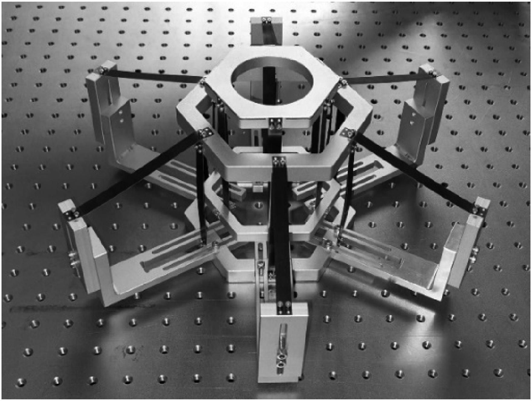
To determine the force-displacement relationship, a static vertical test was conducted on the structure, with the results presented in Figure 13. The figure shows that the force-displacement curve gradually levels off, with the stiffness approaching zero at a displacement of 8 mm, indicating that the stiffness reaches the quasi-zero range. This range extends beyond 7 mm, demonstrating that the structure provides effective vibration isolation for both micro-vibrations and larger amplitude vibrations. When the structure achieves quasi-zero stiffness, the corresponding vertical force is 73 N, which translates to a load capacity of 7.4 kg. Vertical force-displacement curve of quasi-zero stiffness structure prototype.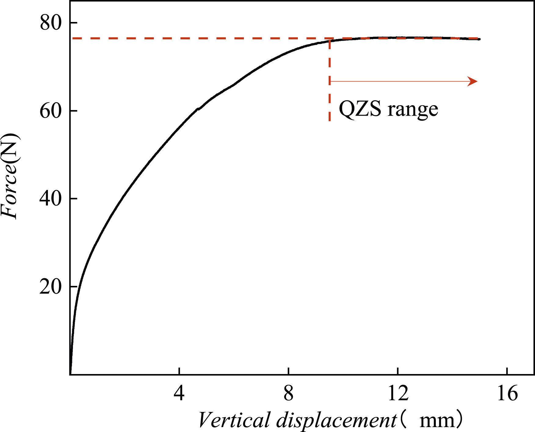
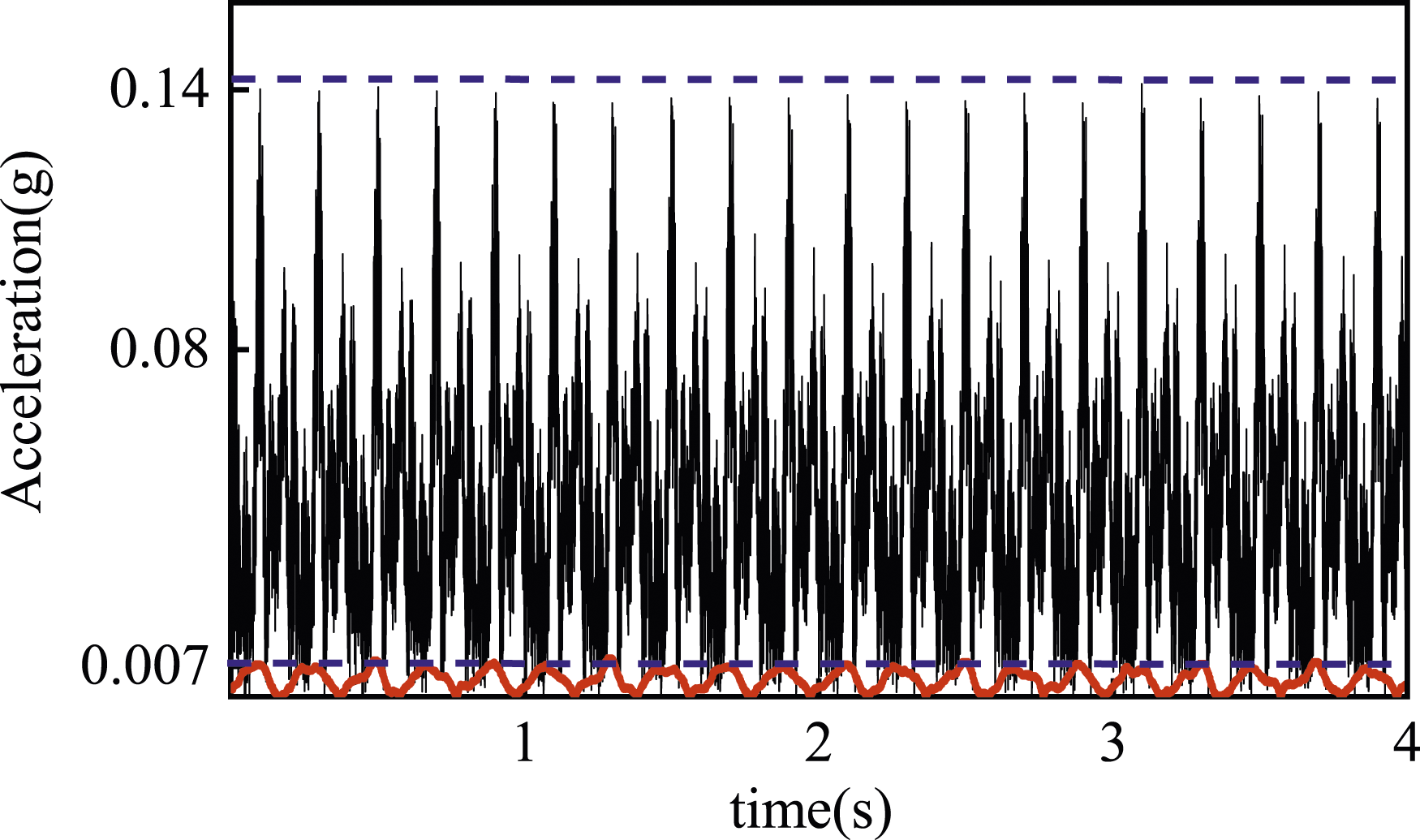
To validate the actual vibration isolation performance of the BQZS structure, a dynamic test was conducted as shown in Figure 14 (in Figure 11, the point marked with ★). The BQZS system, with an applied load, was placed on a vibration table, which subjected the structural base to a 5 Hz sinusoidal acceleration excitation. The acceleration response amplitude (the acceleration output was configured to display amplitude values) results for both the vibration table and the load are presented in Figure 15. The results show that the QZS isolator reduced the acceleration from 0.14 g to 0.007 g (g = 9.8 m/s2), achieving a 95% reduction. This attenuation rate is consistent with that observed under non-ideal loading conditions. Considering the interference signals present in real vibrations, it can be approximated that the system’s natural frequency is below 1 Hz. Vibration isolation test of quasi-zero stiffness structure. Acceleration response amplitude of foundation and load.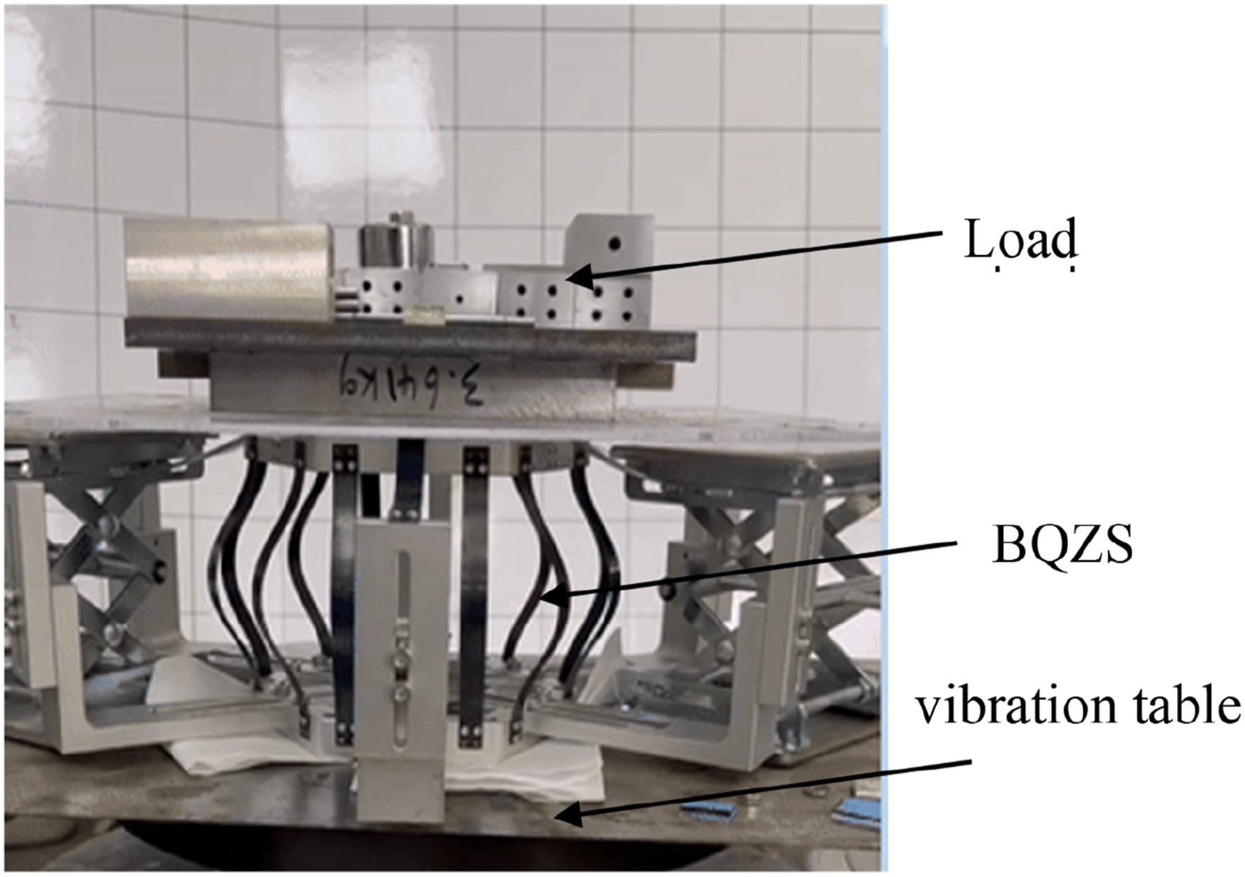
Summary and conclusions
This paper introduces a novel design for a BQZS isolator utilizing slender beams with both positive and negative stiffness. The approach employs the elliptic integral method to address the large deformation of the beams, providing a refined solution to the complex mechanical behavior involved. Key innovations and findings include: 1) The BQZS isolator achieves a unique characteristic output of nonlinear load-bearing combined with linear stiffness, significantly reducing the motion stroke while expanding the QZS range. This dual functionality enhances performance beyond traditional QZS isolators. 2) The BQZS isolator demonstrates exceptional vibration isolation capabilities, with a natural frequency below 1 Hz. Notably, it achieves a 95% reduction in acceleration under a 5 Hz base excitation, effectively managing both micro-vibrations and high-amplitude vibrations. This substantial attenuation underscores its effectiveness and improvement over existing solutions. 3) The design of the BQZS isolator features an integrated, hinge-free configuration that minimizes frictional effects and structural complexity. Additionally, it includes a highly adaptable mechanism where the inclination angle of the negative stiffness beams can be adjusted to accommodate varying loads, offering notable flexibility and performance in diverse applications.
Supplemental Material
Footnotes
Declaration of conflicting interests
The author(s) declared no potential conflicts of interest with respect to the research, authorship, and/or publication of this article.
Funding
The author(s) received no financial support for the research, authorship, and/or publication of this article.
Supplemental Material
Supplemental material for this article is available online.
References
Supplementary Material
Please find the following supplemental material available below.
For Open Access articles published under a Creative Commons License, all supplemental material carries the same license as the article it is associated with.
For non-Open Access articles published, all supplemental material carries a non-exclusive license, and permission requests for re-use of supplemental material or any part of supplemental material shall be sent directly to the copyright owner as specified in the copyright notice associated with the article.