
Abstract
In this study, the acoustic damping performances of the dual Helmholtz resonators were numerically evaluated using a 3D model. The grazing flow passes tangentially through the resonator neck, with a Mach number range of 0 ≤ Ma ≤ 0.1. The numerical model operates by solving the linearized Navier–Stokes equations. The current model is validated through a comparison with experimental data. The model is then utilized to explore the effects of the dual Helmholtz resonators on acoustic transmission loss performance in the presence of a grazing flow. Three key parameters are examined: 1) different implementation configurations of the dual Helmholtz resonators (including Models (b), (c), and (d)), 2) the mean temperature of the grazing flow, and 3) the axial distance between the dual Helmholtz resonators. For comparison, the acoustic damping performance of these dual Helmholtz resonators is compared to the single Helmholtz resonator case (Model (a)). The maximum transmission loss of Model (c) is significantly higher, recording values of 91%, 89.4%, and 92.5% than those observed for Model (a) at Ma = 0, Ma = 0.05, and Ma = 0.1, respectively. It is observed that the dual Helmholtz resonators dramatically increase the transmission loss. Model (c) is demonstrated to be associated with the most significant damping on the acoustic plane waves in comparison with that of Model (a). Additionally, the maximum transmission loss of Model (c) is 23.23 dB, 30.32 dB, and 34.58 dB at mean temperatures of 300 K, 600 K, and 900 K, respectively. Therefore, increasing the mean temperature is shown to be beneficial to enhance transmission losses in the presence of the grazing flow. Furthermore, under Ma = 0.1, the resonant frequency of Model (c) is 127 Hz, 152 Hz, and 172 Hz, corresponding to mean temperatures of 300 K, 600 K, and 900 K. It can be concluded that increasing the temperature has the effect of broadening the resonant frequency, especially at a high grazing flow Mach number. However, increasing the mean temperature results in a reduction of transmission loss in the absence of the grazing flow. In the case of Model (c), a 32 cm axial distance results in a 5.6% larger transmission loss at Ma = 0 and a 26.4% larger loss at Ma = 0.1 compared to a 16 cm axial distance. This indicates that increasing the axial distance between the dual Helmholtz resonators improves transmission loss.
Introduction
Noise control is a critical research area within the engineering field because it has the potential to cause significant harm to combustion systems.1–5 Traditionally, Helmholtz resonators,6–8 micro-perforated panels,9–15 and acoustic metasurfaces16–21 have been effective in absorbing sound by dissipating acoustic energy.22–25 Cheng et al. 26 introduced methods that incorporate porous material filling and micro-perforated embedding to achieve highly effective noise attenuation, especially at low frequencies. Additionally, a theoretical model has been developed to calculate the sound absorption coefficient for a specific type of acoustic metasurface. 27 Among these methods, Helmholtz resonators are particularly attractive due to their ability to stabilize the flow disturbance at relatively lower frequencies with a relatively small volume.28–32 The Helmholtz resonator represents a classical resonance structure, comprising a small orifice and a larger air cavity. In this arrangement, the air within the orifice and cavity serves the dual roles of an air mass and an air spring, respectively.33–36
The resonant frequency depends on the size of the neck and the cavity, and is shown as:
Due to the fluid flow’s ability to accelerate the unsteady vortex shedding from the neck of the Helmholtz resonators,64–69 it becomes essential to investigate the correlation between the flowing fluid and noise absorption performance. To comprehend the connection between vorticity shedding and sound transmission at high Reynolds numbers, Howe et al. 70 proposed a theoretical model to predict the acoustic performance of the Helmholtz resonator by determining the dependence of the Rayleigh conductivity to estimate the rate of dissipation. Jing et al. 71 applied the Kutta condition at the orifice edge to predict the shed vortices and studied the flow excited by sound and acoustic nonlinearity at an orifice. Selamet et al. 72 investigated the impact of grazing flow on the acoustic performance of Helmholtz resonators. Their findings revealed that an increase in grazing flow can lead to a reduction in transmission loss and a shift in the frequency peak to higher values. Zhao et al. and Wu et al.1,73 conducted an investigation into the acoustic performance of liners under conditions of bias-grazing flow and grazing flow. Their findings revealed that the presence of bias-grazing flow can reduce the peak of transmission loss capacity. Zheng et al. 74 proposed a coupled Helmholtz resonator to expand the absorption bandwidth in the presence of grazing flow. Zhao et al. 75 introduced Helmholtz resonators with an extended neck and observed that these resonators with an extended neck enhance transmission loss capabilities and broaden the frequency range under grazing flow conditions compared to Helmholtz resonators without an extended neck. To the best of the authors' knowledge, despite the extensive research on coupled Helmholtz resonators aiming to broaden the frequency range of acoustic attenuation and enhance noise reduction capabilities, there is a noticeable gap in the literatures regarding the investigation of the arrangement of dual Helmholtz resonators. This gap in the research has provided motivation for the current study. Simultaneously, the Helmholtz resonator stands out as a typical passive noise reduction method for thermoacoustic oscillations.76–79 However, there is a dearth of studies exploring the influence of background temperature on the transmission loss of Helmholtz resonators. This gap in the understanding of how background temperature affects the performance of Helmholtz resonators also serves as a motivation for the present study.
In this present study, four 3D models were employed to scrutinize the acoustic performance of the dual Helmholtz resonator, incorporating three distinct configurations. The objective is to discern the impact of the dual Helmholtz resonator layout on acoustic performance. Furthermore, the lack of studies on the influence of background temperature on the acoustic performance of Helmholtz resonators also motivated the current research. The governing equations for these simulations are elaborated in first. The numerical results are then presented, and compares them with experimental data across a frequency range spanning from 50 to 200 Hz. Additionally, the issue of mesh independence is addressed. The study specifically evaluates the effects of three factors: (1) the various configurations of dual Helmholtz resonator with grazing flow, (2) the mean temperature of the grazing flow and (3) the axial distance between the dual Helmholtz resonators. Finally, the key findings regarding the acoustic performance of different configurations of dual Helmholtz resonator are discussed and summarized.
Numerical method
Physical model
This study focuses on a cylindrical duct featuring a Helmholtz resonator. The structures of the dual Helmholtz resonator with three different configurations are illustrated in Figure 1. To provide a basis for comparison, a single Helmholtz resonator is also introduced. D1 and L1 denote the diameter and height of the Helmholtz resonators, measuring 15.3 cm and 24.4 cm, respectively. D2 and L2 refer to the diameter and length of a tube, with values of 4.9 cm and 130 cm, respectively. L3, which is 8 cm in length, signifies the distance between the cavity of the Helmholtz resonators and the tube. L4 represents the distance between the centers of two Helmholtz resonators and is set at 20 cm. Different configurations of Helmholtz resonators.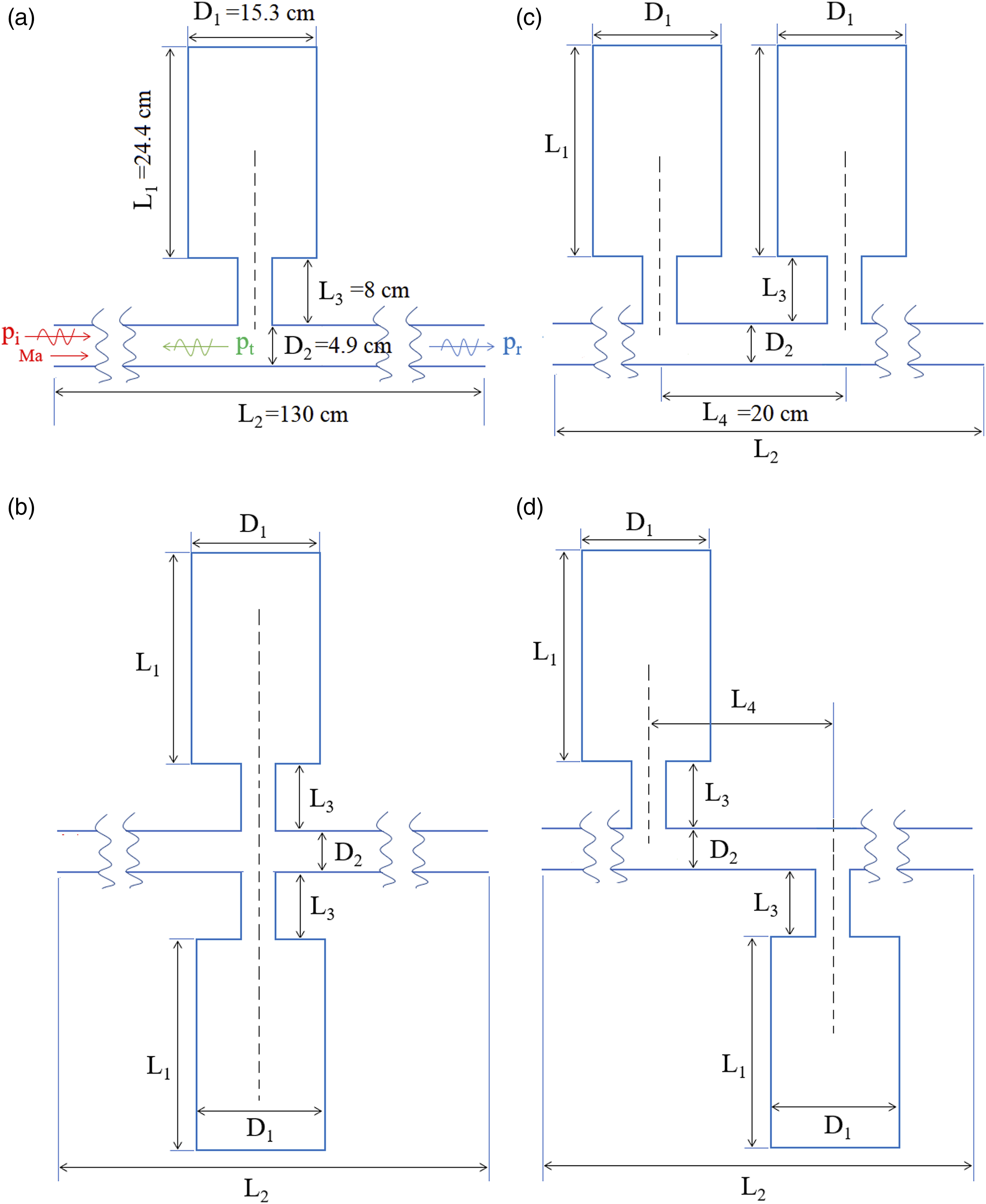
Theoretical equations
In this system, air serves as the medium, and a steady, stationary background flow is present with an average velocity denoted as Uin. The expression for Uin can be defined as follows


The momentum equation is given as

The energy conservation equation is given as


The stress tensor (

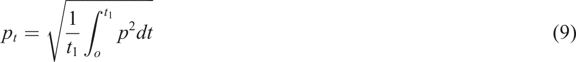
To accurately predict the propagation of plane traveling waves and the acoustic transmission loss from the inlet to the outlet, Perfectly Matched Layer (PML) boundary conditions are introduced at both the inlet and the outlet. Furthermore, the transmission loss between the inlet and outlet can be defined as follows86–89

Mesh independence study and validation
COMSOL is a powerful simulation software that allows users to model and simulate diverse physical phenomena across various engineering and scientific domains. It provides a flexible environment for multiphysics simulations, enabling the integration of different physics phenomena within a single simulation. 93 The utilization of the Linearized Navier–Stokes Frequency Domain interface in current simulations allows for the analysis of fluid flow and acoustic waves in the frequency domain, specifically in the context of linearized Navier–Stokes equations. Widely employed in acoustics and aeroacoustics simulations, this module plays a crucial role in understanding the interactions between fluid flow and acoustic waves. 94
The current simulations are carried out using COMSOL 6.1, where the incident pressure is specified as 1 atm, and the frequencies of the incident plane waves range from 50 Hz to 200 Hz. In Figure 2(a), the grid independence study under Ma = 0 and 0.1 is depicted, utilizing model (a) to explore mesh independence. The coarse mesh, medium mesh, and fine mesh consist of 245,855, 475,358, and 870,439 elements, respectively. The most substantial difference is observed between the coarse and medium meshes under Ma = 0.1, with a variation of approximately 4.5%. Conversely, no notable distinction is found between the medium and fine meshes. To attain an optimal resolution of the shear layer and vortices within the neck-pipe interaction regions,95,96 the medium mesh provides sufficient accuracy for evaluating the acoustic performance in the current simulations. In Figure 2(b), the comparison between numerical and experimental results
8
for Ma = 0, 0.5, and 0.1 is depicted. It is evident that the experimental data closely aligns with the simulation results. As the inlet Mach number increases, the disparity of transmission loss between the experimental and simulation results gradually diminishes. The most substantial difference between the simulation and experimental results is less than 1% at Ma = 0. Consequently, it can be inferred that the current simulations reliably predict the acoustic performance of Helmholtz resonators. (a) Grid independence study under Ma = 0 and 0.1. (b) Comparison between numerical and experimental results
72
under Ma = 0, 0.5, and 0.1.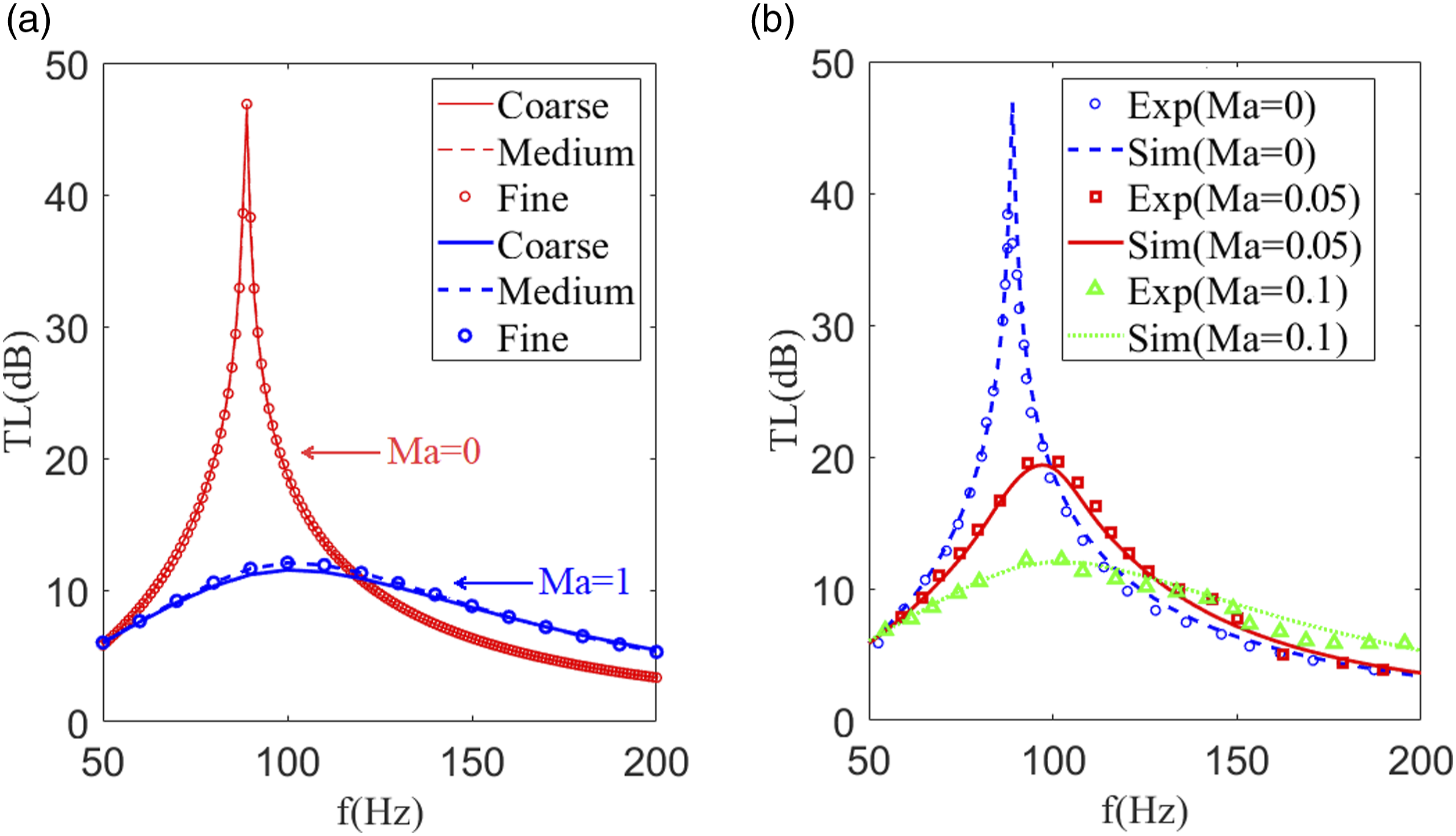
The experimental setup
72
is illustrated in Figure 3. Two loudspeakers are actuated by a signal generator module. Acoustic fluctuations at both the upstream and downstream locations of the component are captured by a pair of pressure sensors. These sensors are positioned 4 cm apart and are flush-mounted with the inner surface of a main duct with a diameter of 4.859 cm. The signals from the pressure sensors undergo post-processing using a multi-channel signal analyzer. To minimize signal noise, each measurement entails averaging 200 ensembles. The pressure sensor switching method97,98 is employed to mitigate the discrepancies in magnitude and phase among the pressure sensors. Experimental setup
72
for measuring the transmission loss of a Helmholtz resonator.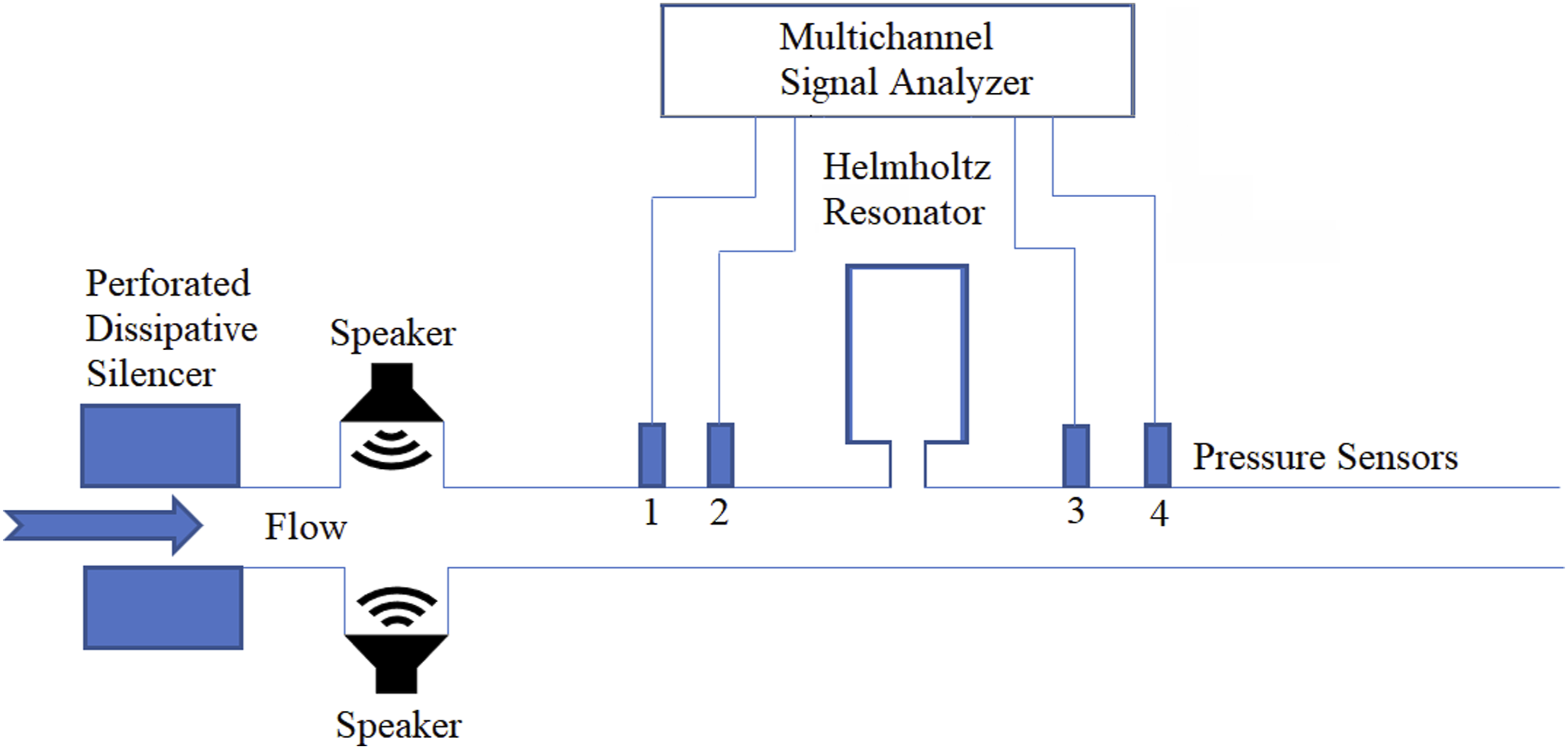
The computational grid is depicted in Figure 4. To ensure the reliability of the current simulations, a medium-sized mesh with 475,358 cells was selected based on the mesh independence study. It should be mentioned that the mesh around the neck-pipe interaction regions has been refined to access the shear layer and vortices. Unstructured mesh of model (a) near the resonator attached regions.
Results and discussion
Effect of the configurations of Helmholtz resonators
In this section, we employ Model (a), Model (b), Model (c), and Model (d) to evaluate the acoustic performance of different configurations of dual Helmholtz resonator under varying grazing flow rates. The incident frequencies span from 50 Hz to 200 Hz with a 1 Hz increment, while the inlet Mach number is set at 0, 0.05, and 0.1. The background temperature is maintained at 300K.
Figure 5 illustrates the variation in transmission loss (TL) for four different configurations of Helmholtz resonators under varying gas flow conditions. It is evident that an increase in the inlet Mach number significantly enhances the resonant frequency. When comparing the single Helmholtz resonator with the dual Helmholtz resonator, it is clear that the latter effectively enhances the ability to increase transmission loss of acoustic propagation, particularly in the case of Models (c) and (d). Notably, the difference in transmission loss (TL) between Models (c) and (d) increases as the inlet Mach number increases, and TL ability of Model (c) performs better than that of Model (d) with grazing flow. It should be mentioned that there exists two range of incident frequency; the TL of Model (d) is higher than that of the Model (c). In conclusion, Model (c) demonstrates the best TL performance, especially in the presence of grazing flow, while Model (a) has a broader range of applications. A specific configuration of a dual Helmholtz resonator is introduced for comparison among these four configurations, and the structure of the resonator can be reviewed in Ref. [99]. The dual Helmholtz configuration, characterized by two distinct cavities, exhibits two dominating frequencies. This observation suggests that the dual Helmholtz resonator possesses a broader frequency band. In comparison to the dual Helmholtz resonator with Models (a), (b), (c), and (d), it can be observed that Models (c) and (d) have a more evident advantage in reducing noise, despite having only one dominating frequency. In the range of 50 Hz to 200 Hz, the transmission loss (TL) of Models (c) and (d) is higher than that of the dual Helmholtz resonator. In conclusion, Models (c) and (d) demonstrate superior suitability for practical applications. Variation of the transmission loss of four configurations of Helmholtz resonators under different grazing flow Mach number.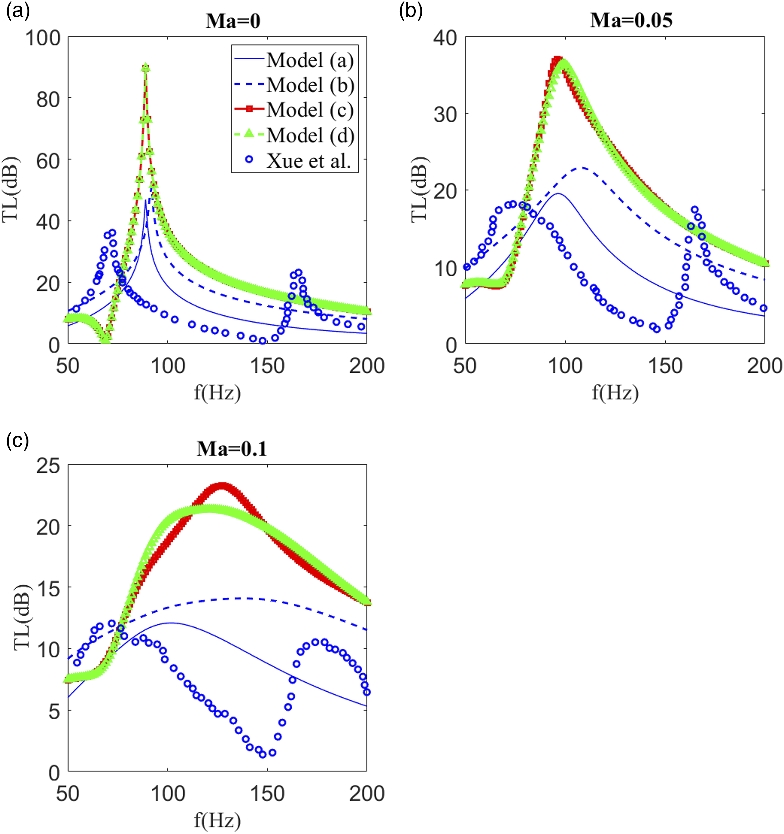
Resonant frequency of different configurations.
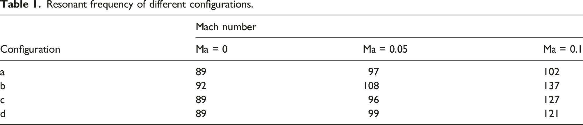
Figure 6 illustrates the variation in the local maximum transmission loss (TLmax) for four configurations of Helmholtz resonators under varying grazing flow rates. It is evident that both in the absence of grazing flow and with grazing flow, Models (c) and (d) substantially enhance the transmission loss (TL) when compared to Model (a). Specifically, without grazing flow, the TL of Models (d), (c), and (b) exceeds that of Model (a) by 88.7%, 88.7%, and 5.1%, respectively. At Mach = 0.05, the TL of Models (d), (c), and (b) surpasses that of Model (a) by 86.5%, 89.4%, and 17.3%, respectively. Similarly, at Ma = 0.1, the TL of Models (d), (c), and (b) outperforms that of Model (a) by 76.1%, 92.5%, and 16.6%, respectively Maximum transmission loss (TLmax) of four configurations of Helmholtz resonators under different grazing flow Mach number.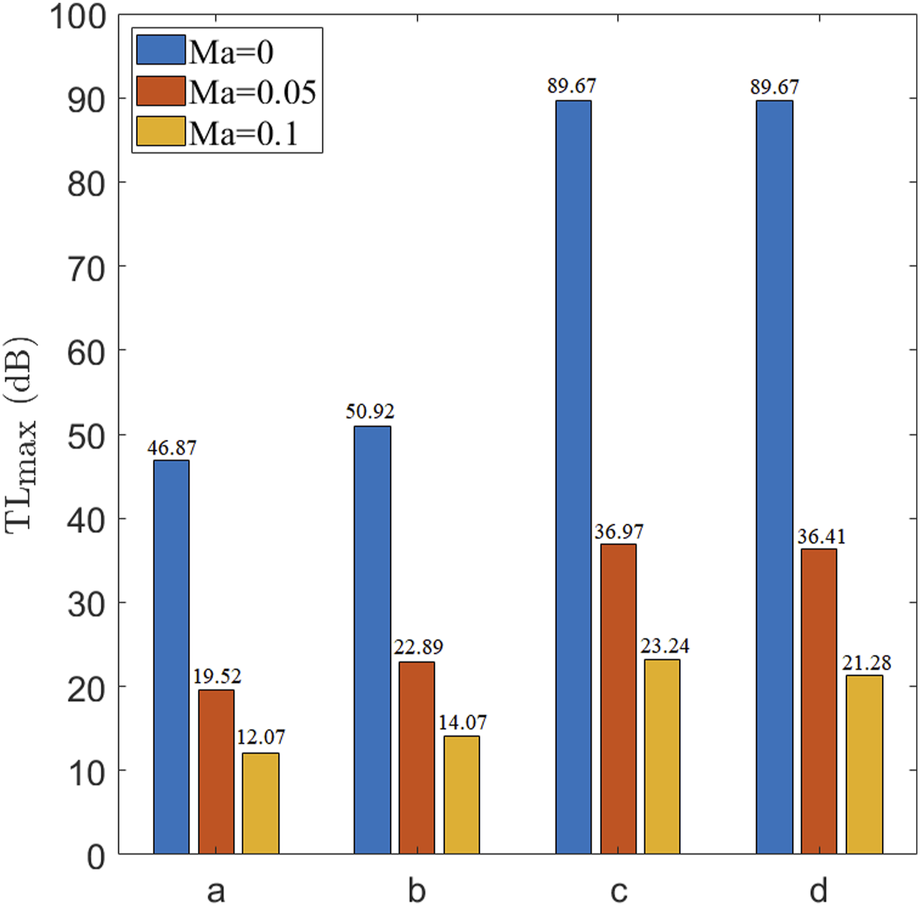
According to previous Refs. [42],[100], and [101], the damping mechanism is primarily attributed to thermo-viscous and shedding losses. In order to gain a deeper understanding of the damping mechanism of resonators, Figure 7 is introduced to compare the vorticity contours near the neck under various inlet Mach numbers. In comparison to Models (a) and (b), Models (c) and (d) exhibit a more pronounced dissipation of vorticity when fluid flows past the Helmholtz resonators. This observation suggests that Models (c) and (d) are beneficial for stabilizing grazing flow. Moreover, there is no distinct different distribution of vorticity between Models (c) and (d). It can be concluded that the layout of the dual Helmholtz resonator has a significant effect on the dissipation of vortex, contributing to the damping of noise. Comparison of vorticity contours near the neck under inlet Mach number of 0.1.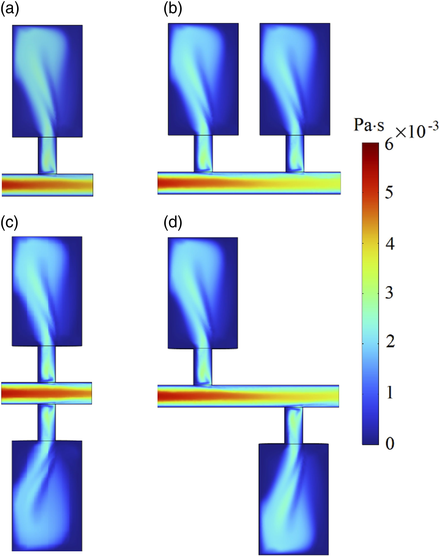
Figure 8 shows the comparison of sound pressure levels near the neck under different inlet Mach number and resonant frequency. Evidently, the sound pressure level at the downstream of Models (c) and (d) is lower than that of Models (a) and (b), both in the presence and absence of grazing flow. An important observation is the existence of a low sound pressure region within the neck area when subjected to grazing flow. As the grazing flow intensifies, this low-pressure zone gradually migrates towards the cavity of the Helmholtz resonators. This phenomenon serves as the primary resonance mechanism contributing to the elevation of the resonant frequency within the Helmholtz resonator affected by grazing flow. Additionally, at Mach = 0.1, it’s evident that the sound pressure level within the neck of Models (b), (c), and (d) is notably closer to the cavity compared to Model (a). Consequently, this proximity results in a higher resonant frequency for Models (b), (c), and (d) in contrast to Model (a). In summary, the primary factor contributing to the increased resonant frequency is the presence of a lower sound pressure level in the neck of Helmholtz resonator. Comparison of sound pressure levels near the neck under different inlet Mach number and resonant frequency.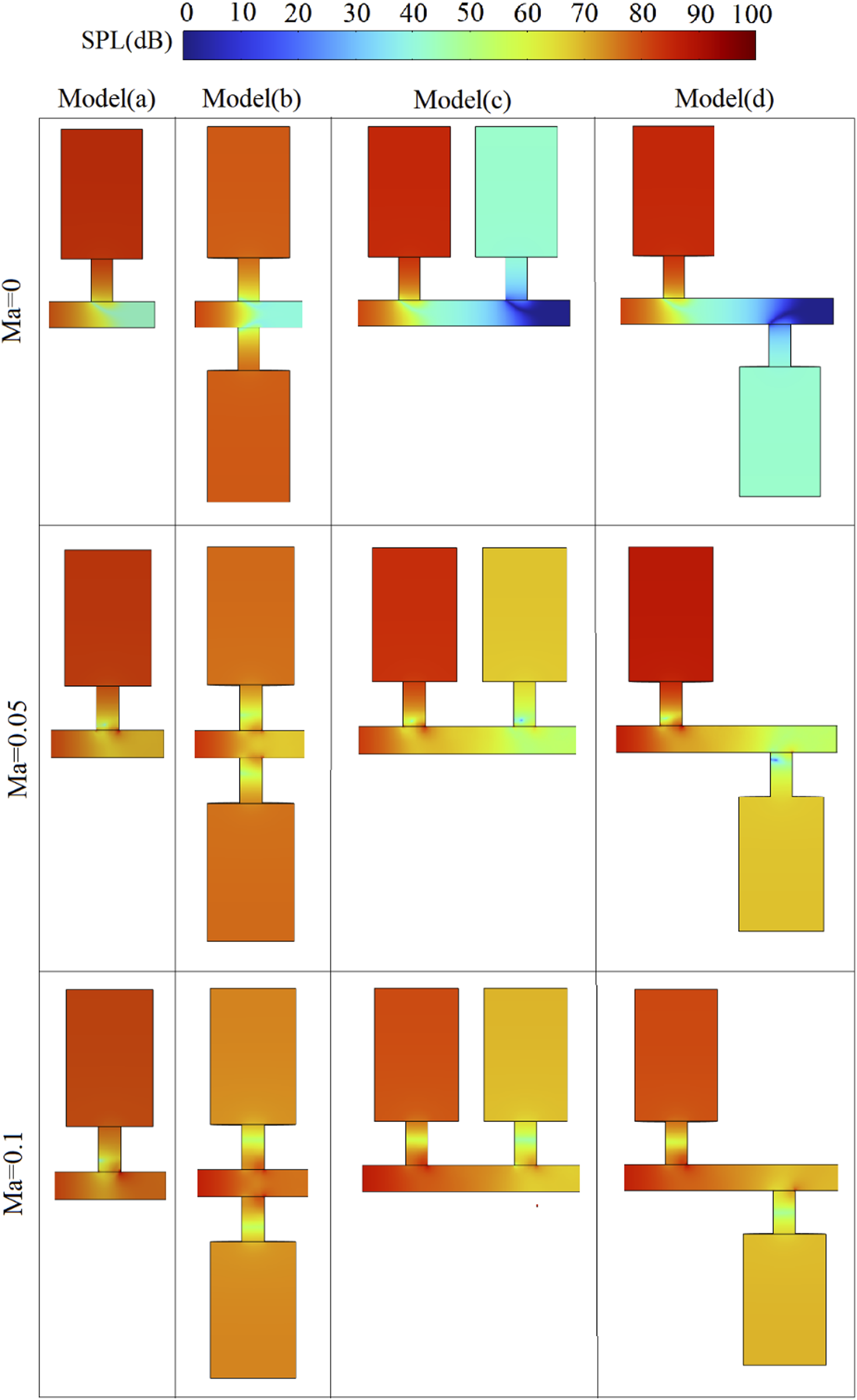
Effect of the mean temperature of the grazing flow
In this section, we utilize Model (a) and Model (c) to assess the acoustic performance of both a single Helmholtz resonator and a dual Helmholtz resonator affected by the mean temperature of the grazing flow. The grazing flow Mach number is varied at 0, 0.05, and 0.1. Furthermore, the mean temperature of the grazing flow is adjusted to 300K, 600K, and 900K. The incident frequencies cover a range from 50 Hz to 200 Hz with a 1 Hz increment. This comprehensive investigation aims to provide a detailed understanding of the acoustic behavior under different flow conditions and temperatures, contributing valuable insights to the field of acoustics and resonator design.
Helmholtz resonators can be widely utilized to enhance combustion stability.23,41 Therefore, investigating the acoustic performance of Helmholtz resonators under the varying mean temperature of the grazing flow is essential. Figure 9 illustrates the variation in the transmission loss of Helmholtz resonators at the different mean temperature of the grazing flow. The findings distinctly demonstrate that, regardless of the presence or absence of grazing flow, the dual Helmholtz resonator consistently outperforms the single Helmholtz resonator in enhancing transmission loss across the various mean temperature of the grazing flow. Conversely, in the presence of grazing flow, elevating the mean temperature of the grazing flow proves beneficial for enhancing the transmission loss of the two configurations. Additionally, the rise in the mean temperature of the grazing flow induces a shift in the resonant frequency towards higher values. This detailed analysis sheds light on the intricate interplay between the mean temperature of the grazing flow, grazing flow, and the acoustic performance of Helmholtz resonators, providing valuable insights for applications related to combustion stability. Transmission loss of Helmholtz resonators under the different mean temperature of the grazing flow.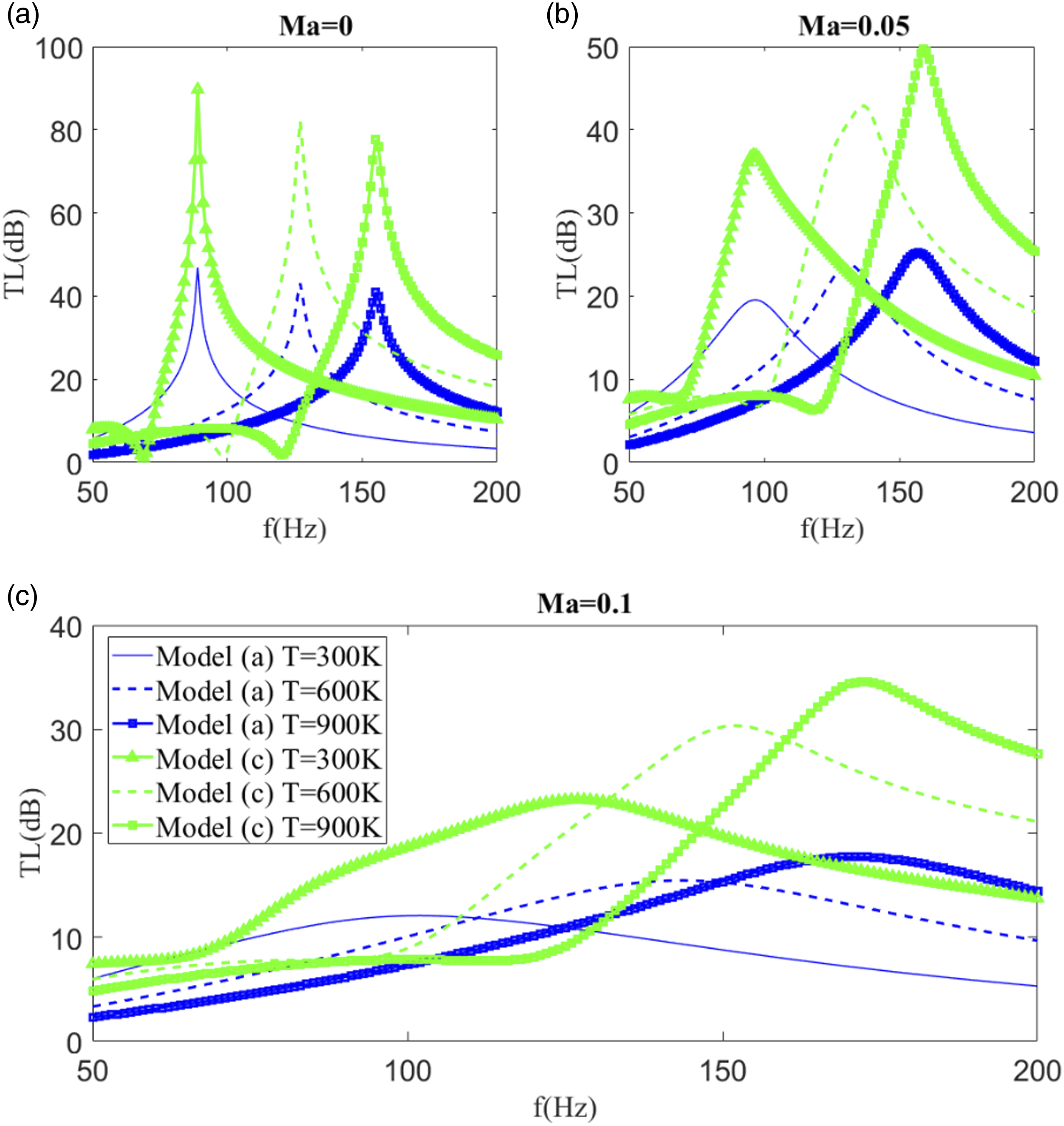
Resonant frequency corresponding to the maximum transmission loss.
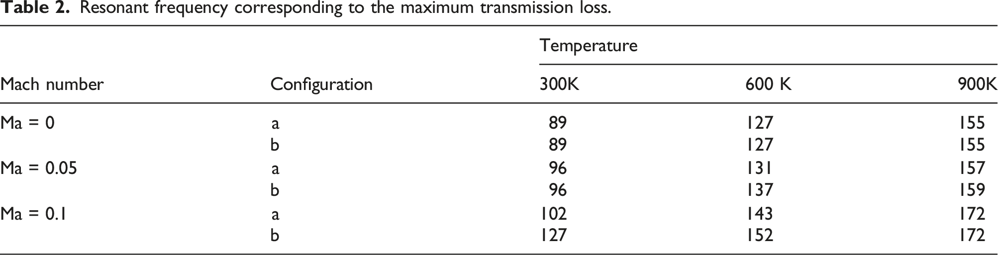
Figure 10 depicts the variation of the local maximum transmission loss (TLmax) across four configurations of Helmholtz resonators under varying Mach numbers of the grazing flow and diverse the mean temperature of the grazing flow. In the absence of grazing flow, both Model (a) and Model (c) experience a reduction in transmission loss (TL) by 12.68% and 13.39%, respectively, when the background temperature shifts from 300K to 900K. However, with grazing flow, elevating the mean temperature of the grazing flow proves advantageous in enhancing the transmission loss of the Helmholtz resonators. Specifically, at Ma = 0.05, Models (a) and (c) exhibit TL enhancements of 26.67% and 34.54%, respectively, with a shift in the mean temperature of the grazing flow from 300K to 900K. Furthermore, at the same Mach number, both Models (a) and (c) demonstrate even greater TL enhancements of 47.01% and 48.86%, respectively, following the mean temperature of the grazing flow shift from 300K to 900K. In summary, the transmission loss (TL) of the dual Helmholtz resonator is highly responsive to changes in the mean temperature of the grazing flow. Maximum transmission loss (TLmax) of two Helmholtz resonator configurations under different grazing flow Mach numbers and the mean temperature of the grazing flow.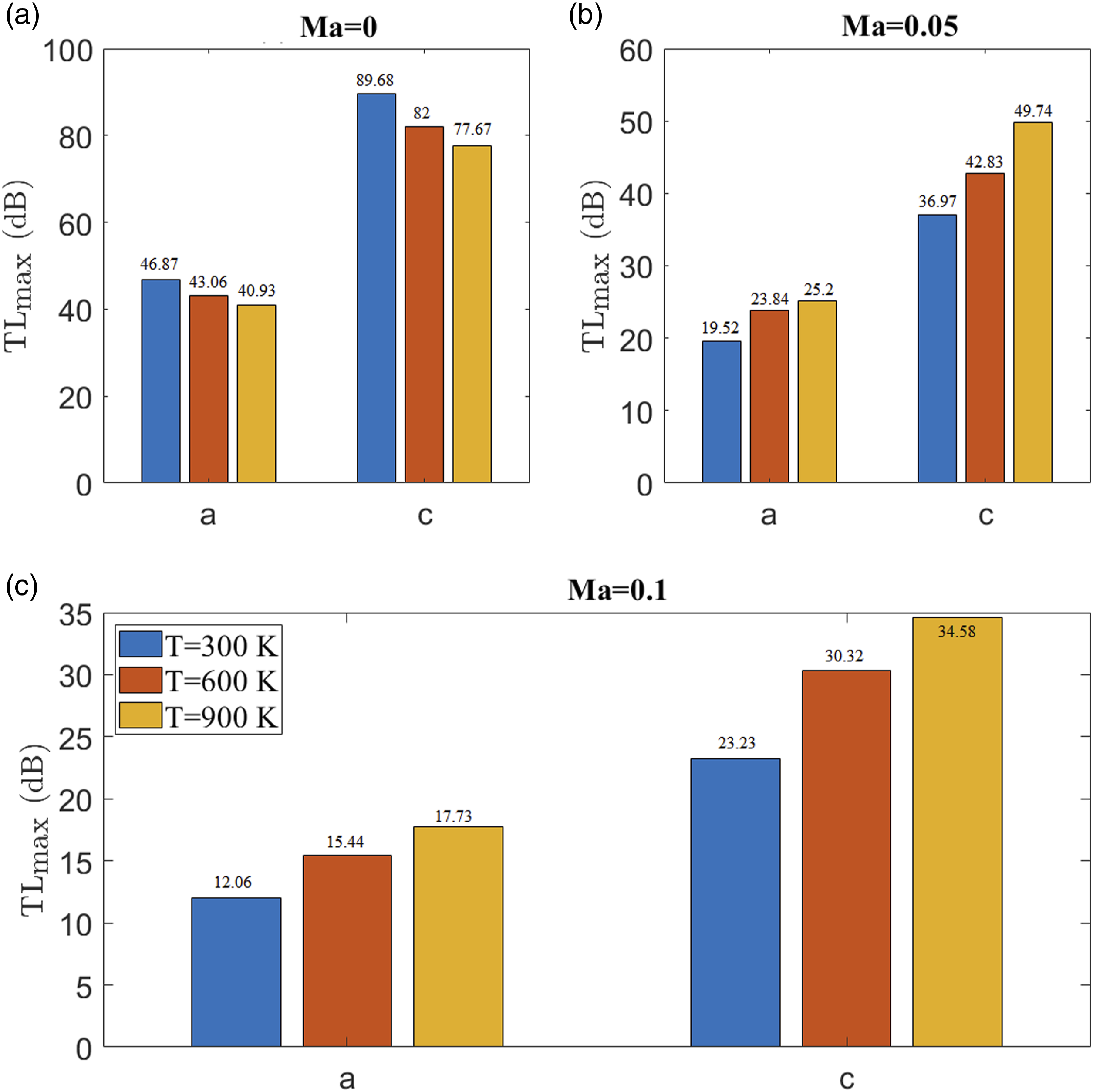
Figure 11 illustrates the sound pressure level near the neck under the various mean temperature of the grazing flow. When there is no grazing flow, there is a noticeable lack of distinction in the sound level distribution between the single Helmholtz resonator and the first Helmholtz resonator of the dual Helmholtz resonator. It can be concluded that the primary enhancement in the transmission loss (TL) of the dual Helmholtz resonator primarily comes from the second Helmholtz resonator under no grazing flow, compared to the single Helmholtz resonator. At the mean temperature of the grazing flow of 300 K, a region of low sound levels is observed in the neck of both the single Helmholtz resonator and the dual Helmholtz resonator. The low sound level area tends to move towards the cavity, which can explain why the resonant frequency tends to be higher with increasing grazing flow. It should be noted that as the mean temperature of the grazing flow increases, the low sound level area moves towards the tube. Furthermore, it is observed that the position of the low sound level area of the dual Helmholtz resonator is closer to the cavity, which can explain why the resonance frequency of the dual Helmholtz resonator is higher than that of the single Helmholtz resonator. With the higher mean temperature of the grazing flow, the low sound level area tends to move towards the tube, indicating that the resonance frequencies of the single Helmholtz resonator and dual Helmholtz resonators tend to converge. Comparison of sound pressure levels of resonate frequency near the neck under different the mean temperature of the grazing flow.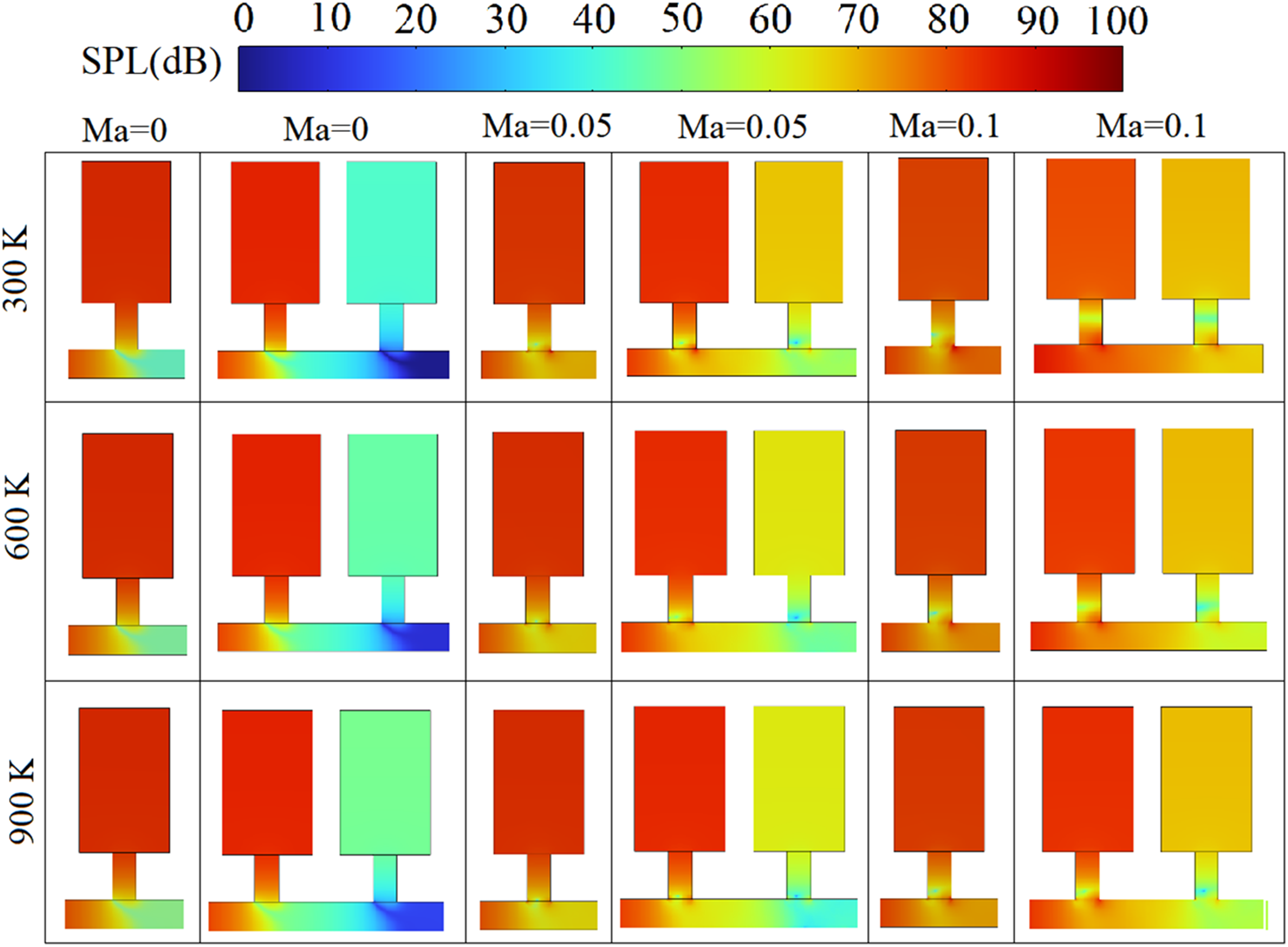
Effect of the axial distance between the dual Helmholtz resonator
In this section, Model (c) is utilized to assess the impact of the axial distance between two Helmholtz resonators on the acoustic performance of the dual Helmholtz resonator. The study involves setting the grazing flow Mach number to 0, 0.05, and 0.1, with a background temperature of 300K. The incident frequency spans from 500 Hz to 200 Hz. The axial distances between the dual Helmholtz resonator are set at 16 cm, 20 cm, 24 cm, 28 cm, and 32 cm, respectively.
Figure 12 shows the variation of the transmission loss of Helmholtz resonators under different axial distance between the dual Helmholtz resonator. Without grazing flow, it is evident that increasing the axial distance between the dual Helmholtz resonator enhances transmission loss (TL). Meanwhile, there is no significant change in the resonant frequency affected by the axial distance. With grazing flow, increasing the axial distance between the dual Helmholtz resonator also tends to increase TL. However, the resonant frequency tends to be lower. This observation suggests that the axial distance between dual Helmholtz resonators plays a crucial role in determining their acoustic performance, both with and without grazing flow. This improvement can be attributed to the increased distance providing ample space for each Helmholtz resonator to dissipate vortex effects. It should be noted that the transmission loss (TL) tends to initially increase, then decrease, and finally increase again as the axial distance between the double Helmholtz resonators increases at Ma = 0.05, which indicates that nonlinear effect becomes more dominant at low grazing flow. Transmission loss affected different axial distance between the dual Helmholtz resonator.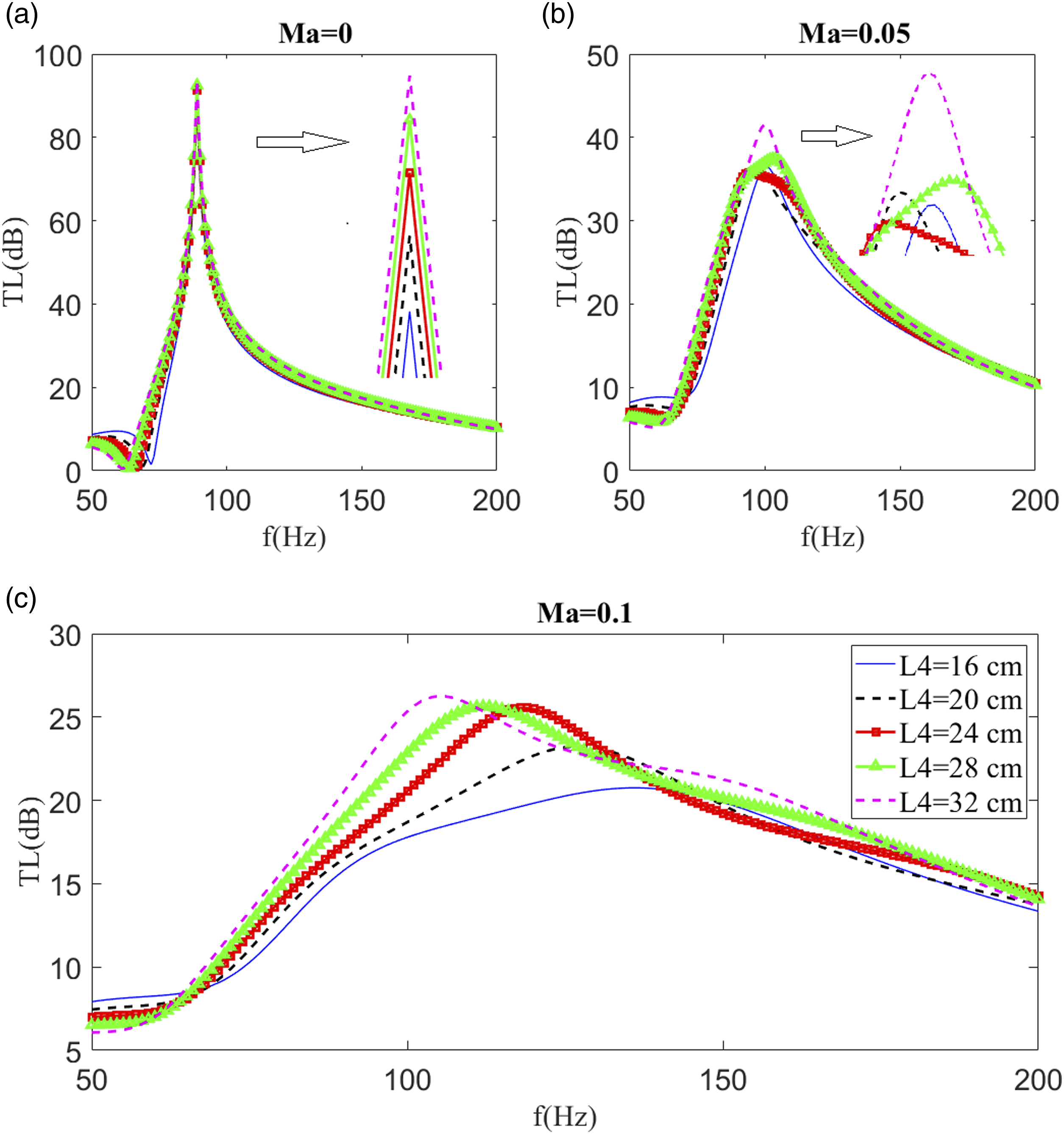
Resonant frequency of the dual Helmholtz resonator with different axial distance.
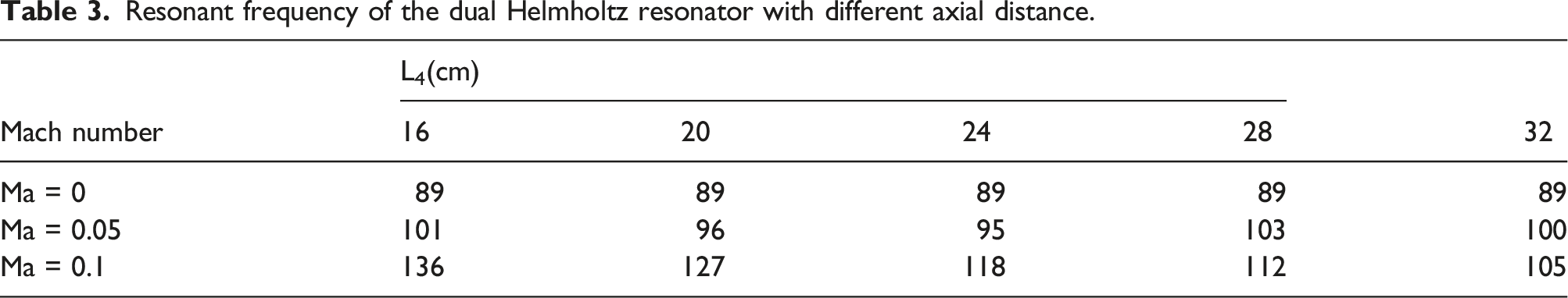
Figure 13 shows the variation of local maximum transmission loss (TLmax) of dual Helmholtz resonator with axial different distance between the dual Helmholtz resonator. The observed transmission loss (TL) demonstrates noteworthy improvements with an increase in the axial distance (L4) of the dual Helmholtz resonator. Specifically, under Ma = 0, the TL for L4 = 32 cm exhibits a 6% enhancement compared to L4 = 16 cm. This enhancement becomes even more pronounced under Ma = 0.05, with L4 = 32 cm surpassing L4 = 16 cm by 12.2%. Additionally, under Ma = 0.1, the TL for L4 = 32 cm outperforms L4 = 16 cm by 11.5%. These findings underscore the positive correlation between the axial distance between the dual Helmholtz resonator and the enhancement of transmission loss, especially notable in the presence of grazing flow. Maximum transmission loss (TLmax) of dual Helmholtz resonator with different distance between the dual Helmholtz resonator.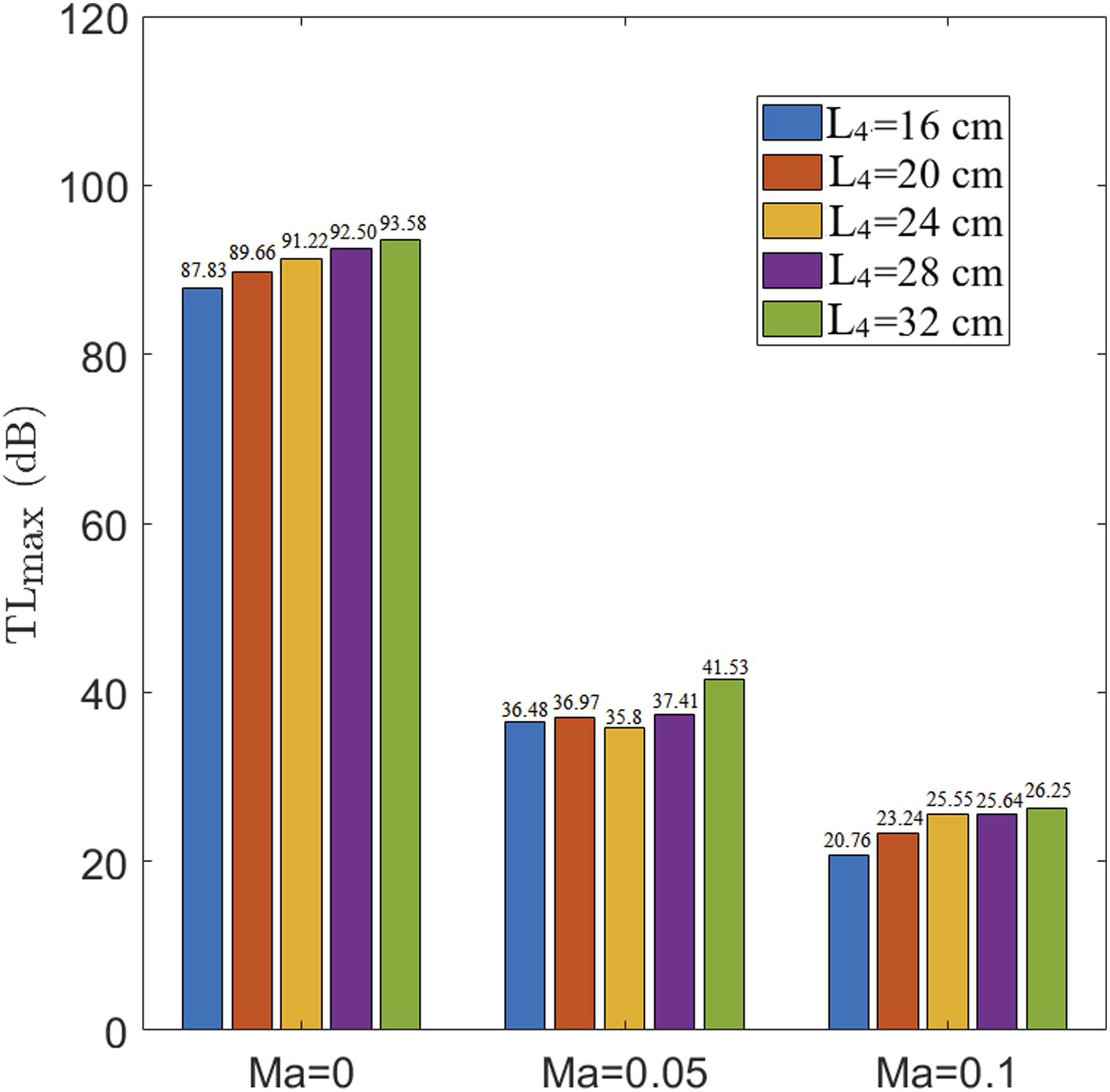
Conclusions
In the present study, 3D simulations are employed to access the transmission loss of four configurations under the influence of grazing flow numerically. The 3D models encompass four configurations: Model (a), Model (b), Model (c), and Model (d). Models (b)–(c) depict dual Helmholtz resonators with distinct layouts of double Helmholtz resonators. For comparative analysis, Model (a), representing a single Helmholtz resonator, is included. This rigorous modeling approach ensures a comprehensive exploration of the acoustic performance across various configurations. Initially, the model is validated by experimental results. Subsequently, three key parameters are used to evaluate transmission loss: 1) different configurations of Helmholtz resonators, 2) the mean temperature of the grazing flow, and 3) the axial distance between the dual Helmholtz resonator. The key observations can be summarized as: (1) Compared with a single Helmholtz resonator, the dual Helmholtz resonator can effectively increase the transmission loss. Among the configurations of dual Helmholtz resonators, Models (c) and (d) exhibit superior performance in transmission loss. The highest transmission loss of Model (c) exceeds that of Model (a) by 91%, 89.4%, and 92.5% for Ma of 0, 0.05, and 0.1, respectively. Simultaneously, the highest transmission loss of Model (d) surpasses that of Model (a) by 91%, 86.5%, and 76.3% for Ma of 0, 0.05, and 0.1, respectively. Thus, Model (c) is the most effective in increasing transmission loss. Moreover, compared to a single Helmholtz resonator, the dual Helmholtz resonators evidently extend the resonant frequency. (2) At Ma = 0, the highest transmission loss of Model (a) is 46.87 dB, 43.06 dB, and 40.93 dB at temperatures of 300K, 600K, and 900K, respectively. In contrast, the highest transmission loss of Model (c) is 89.68 dB, 82 dB, and 77.67 dB at temperatures of 300K, 600K, and 900K, respectively. At Ma = 0, an increase in the mean temperature results in a decrease in transmission loss, observed not only for the single Helmholtz resonator but also for the dual Helmholtz resonator. By contrast, at Ma = 0.1, the highest transmission loss of Model (a) is 12.06 dB, 15.44 dB, and 17.73 dB at temperatures of 300K, 600K, and 900K, respectively. In comparison, the highest transmission loss of Model (c) is 23.23 dB, 30.32 dB, and 34.58 dB at temperatures of 300K, 600K, and 900K, respectively. Thus, the presence of grazing flow (Ma>0) is beneficial in increasing the transmission loss by raising the mean temperature. (3) At Ma = 0, the highest transmission loss of Model (c) is 87.83 dB, 89.6 dB, 91.22 dB, 92.5 dB, and 93.58 dB, corresponding to L4 = 16 cm, 20 cm, 24 cm, 28 cm, and 32 cm, respectively. Meanwhile, at Ma = 0, the highest transmission loss of Model (c) is 20.76 dB, 23.24 dB, 25.55 dB, 25.64 dB, and 26.25 dB, corresponding to L4 = 16 cm, 20 cm, 24 cm, 28 cm, and 32 cm, respectively. Increasing the axial distance between the dual Helmholtz resonator effectively enhances transmission loss, with the effect being less pronounced at high grazing flow. At Ma = 0.1, the resonant frequency of Model (c) is 136 Hz, 127 Hz, 118 Hz, 112 Hz, and 105 Hz, corresponding to L4 = 16 cm, 20 cm, 24 cm, 28 cm, and 32 cm, respectively. At high grazing flow rates, increasing the axial distance between the dual Helmholtz resonator significantly reduces the resonant frequency.
This study aims to investigate the arrangement of dual Helmholtz resonators and enhance their practical applicability in combustion systems. In conclusion, Model (c) is identified as the most effective in increasing transmission loss, and increasing the distance between dual Helmholtz resonators proves to be advantageous for enhancing transmission loss. The study also provides valuable research insights into the practical application of Helmholtz resonators in higher background temperatures, and stabilize combustion system,102–104 with swirling flame, 105 non-premixed flame, 106 and premixed flame. 107 For the future research, the incorporation of porous medium stands out as a typical method for noise reduction.108,109 The combination of Helmholtz resonators and porous medium is a promising direction to further increase transmission loss.
Footnotes
Author Contributions
H. Z. conducted numerical simulations. H. Z. processed and analyzed the data and discussed the results with D. Z. D. Z. conceived and initialized the project. H. Z., D. Z., and X. D. contributed to the paper writing and English editing.
Declaration of conflicting interests
The author(s) declared no potential conflicts of interest with respect to the research, authorship, and/or publication of this article.
Funding
The author(s) disclosed receipt of the following financial support for the research, authorship, and/or publication of this article: This work was financially supported by the University of Canterbury (No. 452DISDZ) New Zealand and Science Center for Gas Turbine; P2022-C-II-003-001.