
Abstract
In this work, modified designs of Helmholtz resonators with extended deflected neck are proposed, numerically evaluated and optimized aiming to achieve a better transmission loss performance over a broader frequency range. For this, 10 Helmholtz resonators with different extended neck configurations (e.g. the angle between extended neck and the y-axis) in the presence of a grazing flow are assessed. Comparison is then made between the proposed resonators and the conventional one, i.e. in the absence of an extended neck (i.e. Design A). For this, a two-dimensional linearized Navier Stokes equations-based model of a duct with the modified Helmholtz resonator implemented was developed in frequency domain. The model was first validated by comparing its numerical predictions with the experimental results available in the literature and the theoretical results. The model was then applied to evaluate the noise damping performance of the Helmholtz resonator with (1) an extended neck on the upstream side (Design B); (2) on the downstream side (Design C), (3) both upstream and downstream sides (Design D), (4) the angle between the extended neck and the y-axis, i.e. (a) 0°, (b) 30°, and (c) 45°, (d) 48.321°. In addition, the effects of the grazing flow Mach number (Ma) were evaluated. It was found that the transmission loss peaks of the Helmholtz resonator with the extended neck was maximized at Ma = 0.03 than at the other Mach numbers. Conventional resonator, i.e. Design A was observed to be associated with a lower transmission loss performance at a lower resonant frequency than those as observed on Designs B–D. Moreover, the optimum design of the proposed resonators with the extended neck is shown to be able to shift the resonant frequency by approximately 90 Hz, and maximum transmission loss could be increased by 28–30 dB. In addition, the resonators with extended necks are found to be associated with two or three transmission loss peaks, indicating that these designs have a broader effective frequency range. Finally, the neck deflection angles of 30° and 45° are shown to be involved with better transmission loss peaks than that with a deflection angle of 0°. In summary, the present study sheds light on maximizing the resonator’s noise damping performances by applying and optimizing an extended neck.
Introduction
Helmholtz resonators are widely used to reduce unwanted aeroacoustics noise in turbo-machineries or to stabilize combustion systems in gas turbines or aircraft engines.1,2 Modern combustion systems are designed to achieve low NOx emission. However, they are more susceptible to self-excited thermoacoustic oscillations. It is known as thermoacoustic instability3–5 and characterized with large-amplitude acoustic oscillations. Such large oscillations could cause engine structural vibration and even mission failure. To attenuate thermoacoustic instability, Helmholtz resonators could be applied to dissipate combustion-driven acoustic oscillations and to stabilize the combustors. 6
Transmission loss analyses of Helmholtz resonators have been recently extensively studied.7,8 Zhao et al. 9 studied the resonant frequency and maximum transmission loss of a resonator with different neck shapes, neck structures and its lengths. Lu et al. 10 studied the maximum transmission loss of an asymmetric Helmholtz resonator in presence of a grazing flow by changing the neck offset distance from the center of the resonator. Wu et al. 11 studied the influence of different neck lengths and neck diameters on the aeroacoustics attenuation performance of Helmholtz resonators. Shi et al. 12 found that Helmholtz resonators with spiral necks have low frequencies. Such resonators can achieve a high noise reduction in a very small space. In addition, these resonators have multiple resonant frequencies. Furthermore, Zhang et al. 6 studied the damping effect of Helmholtz resonators by using numerical approaches and conducting experimental tests. They found that the combustion system can be stabilized in a wide frequency range by adjusting the neck cross-sectional area of the Helmholtz resonator in real time.
Recent researches on Helmholtz resonators are conducted via numerical and experimental approaches. Zhao et al. 13 numerically studied a coupled Helmholtz resonator to broaden the damping frequency range via using multiple Helmholtz resonators. Two or more transmission loss (TL) peaks were observed for the coupled Helmholtz resonators for different grazing flow Mach numbers (Ma). Although the resonant frequency of a conventional Helmholtz resonator has been theoretically derived in the absence of a grazing flow, there is still a lack of understanding regarding the noise reduction mechanism of a Helmholtz resonator with complex structures, especially in the presence of a tangential flow (i.e. grazing flow).14–17 Yang 18 conducted finite element simulations on a two-way perforated pipe. He found that the perforation rate has a slight effect on the acoustic performance at the low-frequency range, and a significant impact on the acoustic performance at the mid-frequency range. Meanwhile, Guan et al. 19 designed a Helmholtz resonator with a rigid baffle implemented in its cavity. They studied the effect of the configurations of the baffle and the neck shape. It is found that the optimized design has an additional transmission loss at approximately 400 Hz. Besides, they discovered that changing the neck shape from the traditional shape to an arc shape leads to a shift of the main resonant frequency by approximately 20%. Pan et al. 20 studied the acoustic attenuation performance of two coupled Helmholtz resonators in presence of a grazing flow. They found that the grazing flow direction affects the transmission loss peaks and the resonant frequencies of the resonators. It is also observed to contribute to ‘whistling’ phenomenon. Moreover, it is found that as the grazing flow Mach number is increased, the transmission loss is generally decreased.
Unconventional Helmholtz resonators with more complex structures are designed and studied recently to optimize its effectiveness. Selamet et al.21,22 experimentally studied Helmholtz resonators with extended necks. They investigated the damping effect of different neck lengths and neck shapes, as well as different perforations on the extended neck, on the transmission loss and the resonance frequency. It was found that the resonant frequency can be determined by the length, shape, and perforation pattern (or porosity) of the extended neck without changing the volume of the resonator cavity. Their studies inspired the present work on improving the noise attenuation performance of Helmholtz resonators via implementing a deflected extended neck. Note that the deflection angle of the extended neck is relative to y-axis. 23 Most of foregoing studies on the aeroacoustics performance of conventional and unconventional Helmholtz resonators were conducted in the time domain by solving Navier-Stokes (N-S) equations24,25 or by conducting experimental measurements. However, these research approaches are computationally costly and time-consuming. To save computational time and cost, and to evaluate the noise attenuation performance, frequency-domain simulations could be applied to examine the noise damping performances of Helmholtz resonators with deflected extended necks in presence of a grazing flow. This partially motivated the present work.
In this study, 2 D numerical models of unconventional Helmholtz resonators with deflected extended necks were developed using linearized N-S equations. These models were built in the frequency domain and were used to estimate the aeroacoustics attenuation performance of Helmholtz resonators in four different configurations, as a grazing flow with a Mach number Ma is present. For comparison, Design A (i.e. the conventional Helmholtz resonator) was selected as the reference case. The frequency-domain model was first validated by comparing with the experimental data available in the literature. In the Description of the numerical model section, a two-dimensional frequency-domain model of a duct with a Helmholtz resonator implemented is developed. The model is validated first by considering with the conventional Helmholtz resonator (i.e. no extended neck) via comparing with theoretical and experimental results available in the literature. The model is then applied to study the transmission loss performance of the proposed Helmholtz resonator with extended neck. In the Results and discussion section, the effects of (1) the grazing flow Mach number, (2) the deflected angle between the extended neck and y-axis, (3) the extended neck implementation configuration are examined and discussed in terms of their noise damping performance. Finally, the key findings of the proposed Helmholtz resonators with deflected extended necks are summarized in the Discussion and conclusions section.
Description of the numerical model
This study considers a cold-flow pipe with a Helmholtz resonator applied, as shown in Figure 1.
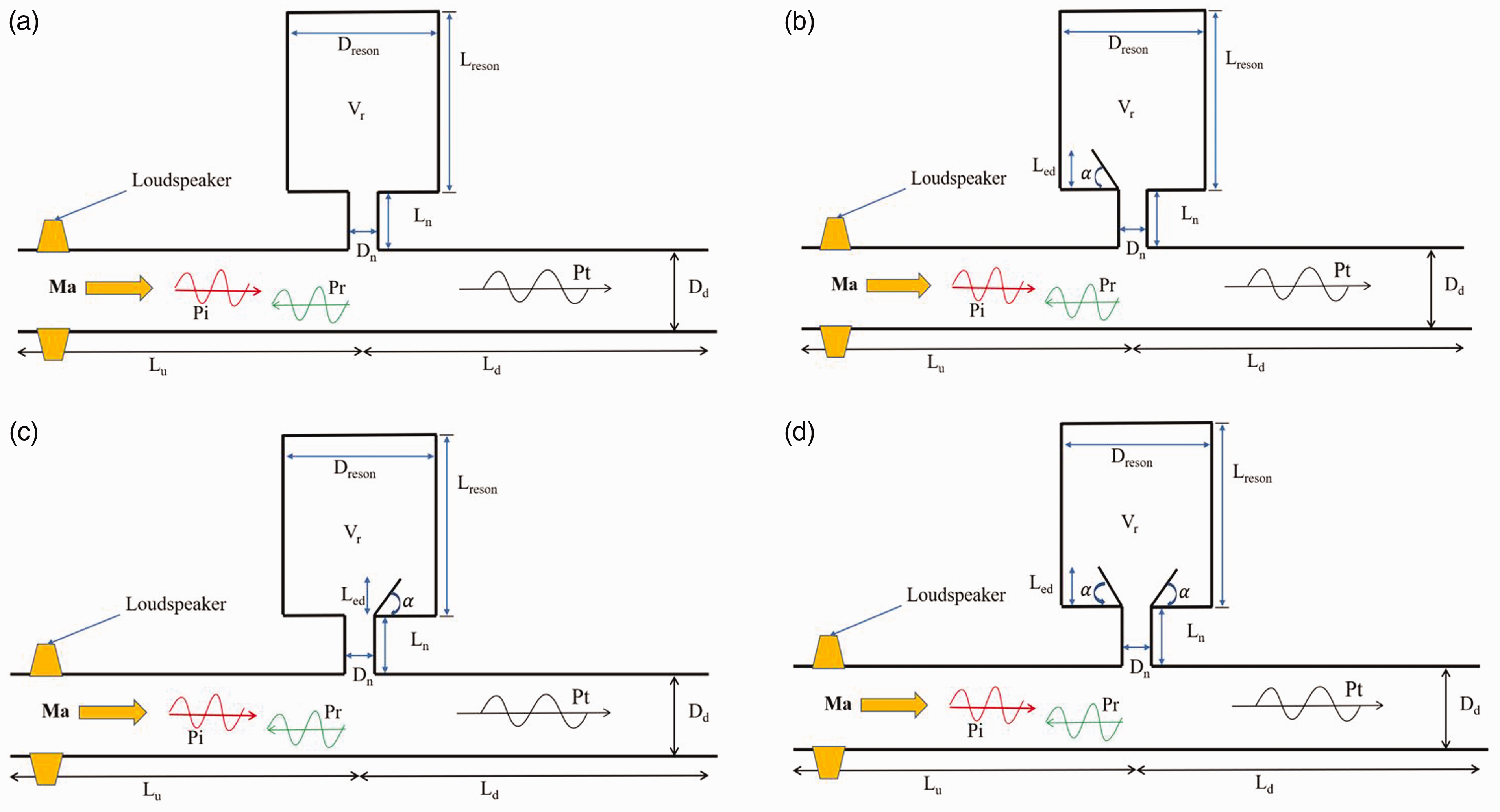
Schematic drawing of the numerical models of 4 Helmholtz resonators with different extended necks configurations. (a) Design A, (b) Design B, (c) Design C and (d) Design D.
The Helmholtz resonators are designed in four different configurations in the presence or absence of extended necks. Figure 1(a) shows the conventional Helmholtz resonator (i.e. no extended neck). It is labeled as Design A. It is used as a reference case to benchmark our proposed designs (see Figure 1(b) to (d)). The deflected extended neck designs are a follow-up research inspired by the previous work. 5 Figure 1(b) shows the modified resonator with an extended neck applied on the upstream side, i.e. Design B (referring to the flow direction). Figure 1(c) shows a resonator with an extended neck implemented on the downstream side, i.e. Design C. The angle α between the extended neck and the y-axis (perpendicular to the flow direction) in both Design B and C could be varied, i.e. α = 0°, 30°, or 45°. Figure 1(d) shows a resonator with extended necks applied on both upstream and downstream sides. This is Design D. Same to Designs B, C, α in Design D could be set to 0°, 30° or 45°. In addition, α = 48.321° in Design B is considered (i.e. the extended neck touched the cavity inner sidewall). For consistency, the vertical height of the extension necks of the tested Helmholtz resonators is remained to be 0.05 m in all simulations.
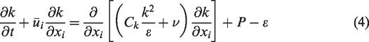
To predict the aeroacoustics damping performances of the proposed Helmholtz resonators as illustrated in Figure 1(a) to (d), a 2 D frequency-domain model was developed by solving linearized N-S equations for incompressible viscous flow at a relatively low Mach number. The governing equation of mass conservation is

The momentum conservation equation is given as

The energy conservation equation is described as

Geometric dimensions and meshes of the modelled Helmholtz resonators
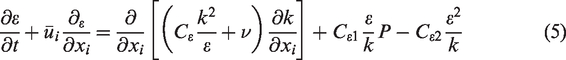
The geometries and flow conditions of the pipe with the modelled Helmholtz resonators implemented in presence of the grazing flow are summarized in Table 1.
Geometries and flow conditions of a cylindrical pipe with Helmholtz resonator.
Figure 2 shows the numerical meshes used for the current simulations. To achieve a good resolution by capturing the shear layer and vortex shedding at the neck-pipe junction region,26,27 total meshes of 652,460 cells and 634,044 cells were selected by conducting an independent mesh study. The selected mesh is justified by validating the present model with experimental results in the literature,3,5 as discussed in following section, i.e. the Model validation section. To capture the aeroacoustics performance of the Helmholtz resonators over the interested frequency range, the frequency step is set to 2 Hz. Further reducing the frequency step is possible. However, it increases the computational cost and time.
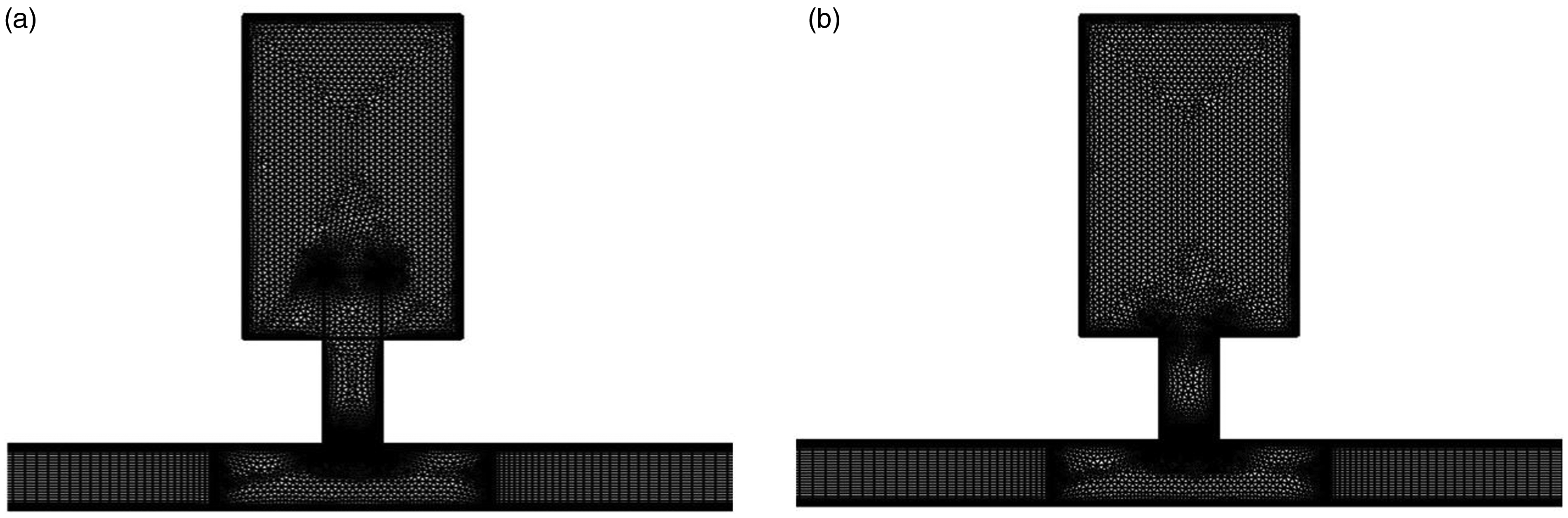
Unstructured meshes of the modelled Helmholtz resonator attached to the duct. (a) 652460 cells and (b) 634044 cells.
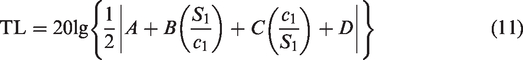
When plane waves are travelled in the pipe and propagate downstream, it is assumed that the pipe outlet satisfies the requirements of PML (Perfect Matched Layer). The TL of the piping system with the resonators attached is determined as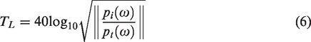
Model validation
Model validation by experimental results
The linearized N-S equation with the κ-ε turbulence model was solved using COMSOL Multiphysics v5.3a. The present model is validated by comparing with the experimental data and the numerical results in the literature. 5 To be consistent with the experimental measurements reported by Selamet and Lee, 5 the tested frequency range is set to 50≤ω/2π ≤ 200 Hz in this study. Figure 3 illustrates the comparison between the present results and the experimental ones, 5 as there is no grazing flow, i.e. Ma = 0. It can be seen from Figure 3(a) and (b) that the numerical results obtained from two different cases agree well with the experimental ones.
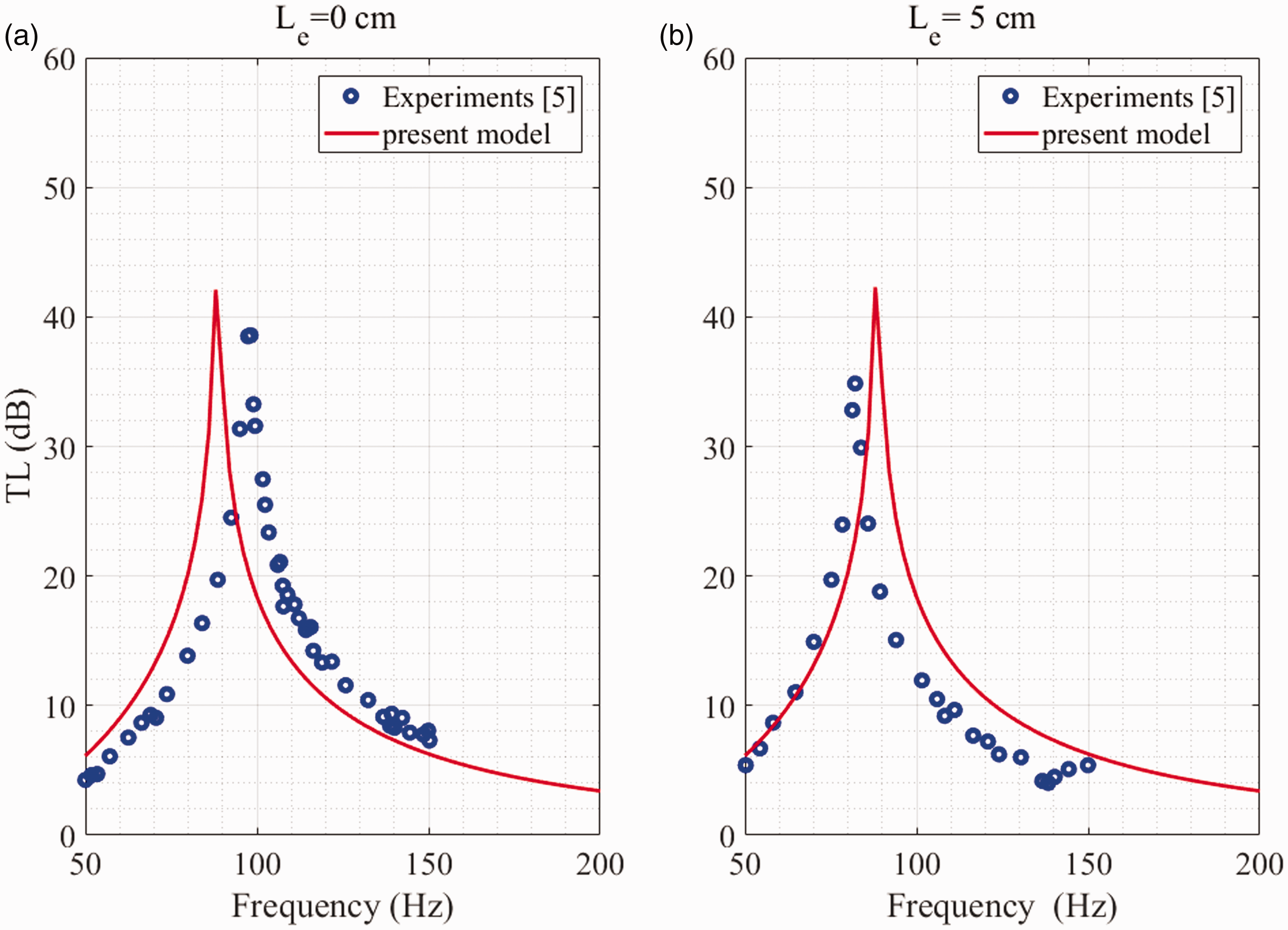
Comparison of the present simulation results with the experimental data in Selamet and Lee, 5 as there is no grazing flow, i.e. Ma = 0 and extended neck with different lengths. (a) α = 0°, and Le = 0 m, (b) α = 0°, and Le = 0.05 m.
Further validation of the present model is performed by considering the effect of the grazing flow. Figure 4 shows the comparison of the present results simulating the Helmholtz resonator (Le = 0 m) in presence of a non-negligible grazing flow with the experimental ones in Selamet et al. 3 It can be seen that a generally good agreement between the present model and the experimental measurements 3 was obtained for three different Mach numbers.
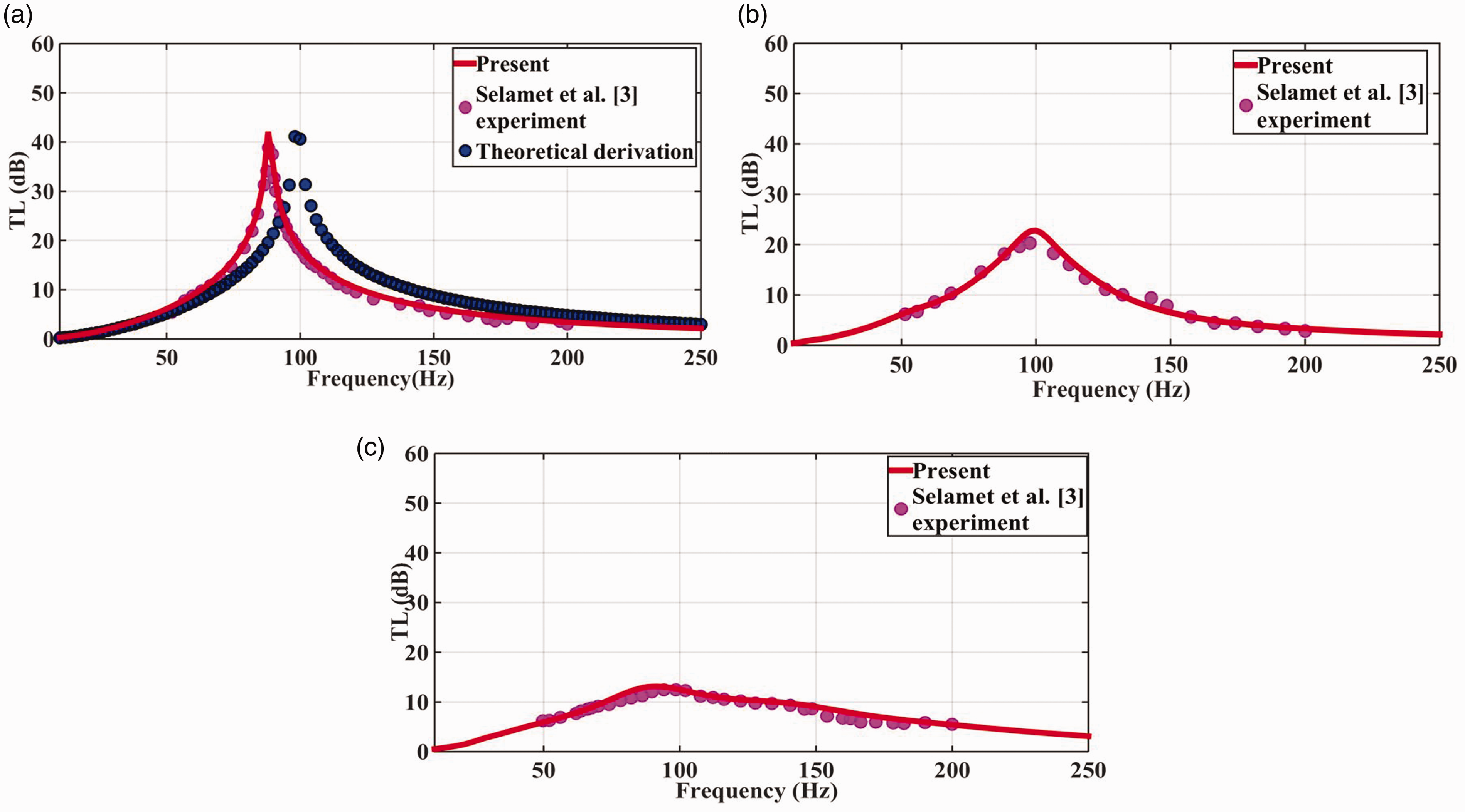
Comparison of the simulation results of the proposed model with the experimental data obtained by Selamet et al. 3 in presence of a mean grazing flow. (a) Ma = 0, (b) Ma = 0.05 and (c) Ma = 0.1.
In general, these comparisons (see Figures 3 and 4) reveal that the present model could be applicable to estimate the noise damping performances of the proposed Helmholtz resonators (see Figure 1) with deflected extended necks in the presence of a grazing flow.
Model validation with theoretical results
As the conventional Helmholtz resonator is represented as Design A, and the proposed new designs (see Figure 1(b) to (d)) are spin-off, it is necessary to validate the Design A. Luckily, Design A is involved with a theoretical prediction of the resonant frequency and TL (transmission loss). The theoretical results of Design A can be obtained by substituting its parameters into equation (7)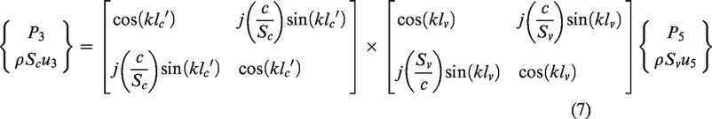
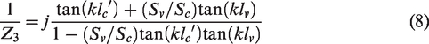
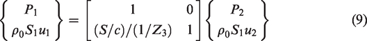
Substituting equation (8) into equation (9)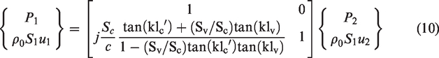
Resonance (i.e. infinite transmission loss) of the Helmholtz resonator occurs as
If the frequency is very low and satisfies 
Hence, the resonance frequency of Design A is given as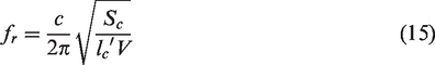
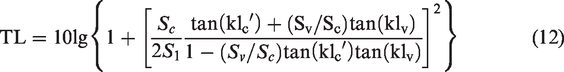
The theoretical results obtained by using equations (12) and (15) are shown in Figure 4(a), when Ma = 0. It can be seen that there are some discrepancies between the theoretical resonant frequency and maximum TL with the experimental and numerical ones. However, the difference is less than 10%. This could be mainly due to the end correction effect. Therefore, the numerical model is generally acceptable, since it agrees well with the experimental results.
Results and discussion
Effect of the grazing flow Ma
The effect of the grazing flow Mach number on the proposed Helmholtz resonators’ noise damping performance is examined30–34 to shed lights on the practical resonator application in a real automobiles.3,35–37 Figure 5 shows the variation of the maximum transmission loss (TLmax) of Designs B, C, D and with Design A at different α, as Mach number Ma is set to six different values. It can be seen that the maximum transmission loss peak for Ma = 0.03 is higher than those of the other Mach numbers in most cases. Furthermore, it can be seen that the maximum Mach number corresponding to the lowest TLmax and the transmission loss curve of Ma = 0 to Ma = 0.03 are higher than that of Ma = 0.05–0.12. This indicates that the Helmholtz resonator has a good aeroacoustics attenuation performance at a relatively low grazing flow Mach number. This corresponds to the curve of Design A in the literature. As the neck deflection angle α is increased, the overall transmission loss peak is decreased in general (see Figure 5). A closer observation of Figure 5 reveals that the overall transmission loss peaks of Designs B and D are higher than that of Design C. This is due to the fact that the extended neck on both upstream and downstream sides or on the upstream side causes more intensified vortex shedding than that of the downstream side in the presence of a grazing flow. It can also be seen from Figure 5(a) that when the deflection angle α of the extended neck is α = 45° and Ma = 0.1, the transmission loss peak are higher than others. This shows that this deflected angle of the modified Helmholtz resonator may achieve a better performance at a relatively high frequency. Similarly as shown in Figure 5(b), when Ma = 0.12 and α = 0° for Design C, the Helmholtz resonator has a higher transmission loss performance than that of Design A. The TL variation curve shows the transmission loss peak at a higher frequency than that of Design A in the 165–170 Hz range.
Variation of the maximum transmission loss (TLmax) of Designs B, C, and D with Design A at different deflected angles, as Mach number Ma is set to six different values.
Figure 6 shows the variation of the transmission losses of Designs B, C, and D with the forcing frequency, as the extended neck deflection angle α is set to 0° and Ma is set to six different values. As shown in Figure 6, it is clear that the maximum TL is decreased, as Ma is increased from 0 to 0.12 in most cases. When the deflection angle α is 0 degree, i.e. α = 0°, Design C is involved with the minimum TLmax in comparison with those of Design B and Design D, as Ma = 0. As Ma is increased to 0.1, Design C has the maximum TLmax than Design B and Design D.
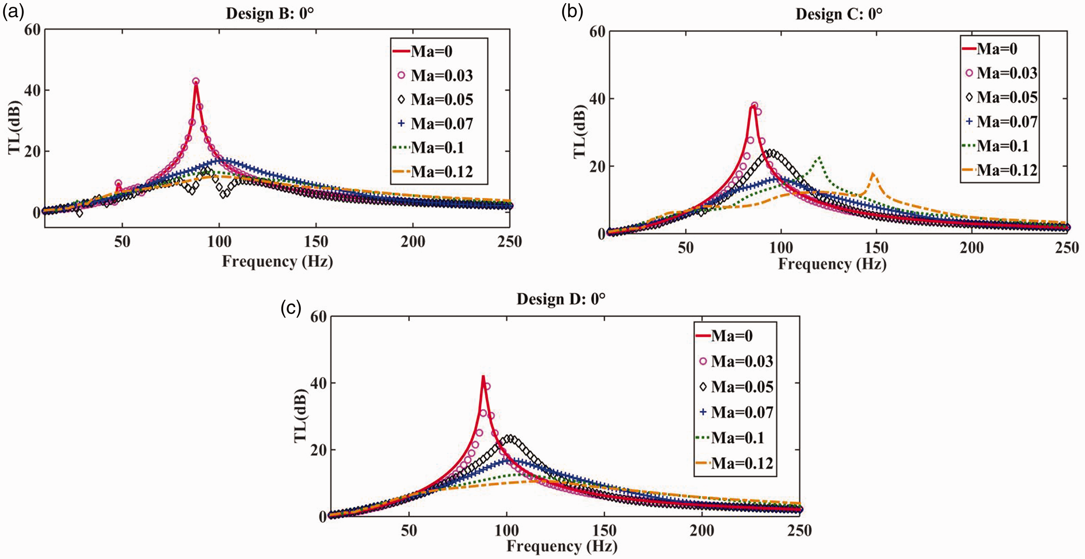
Variation of the maximum transmission loss (TLmax) of Designs B, C, and D, as the extended neck deflection angle is set to 0° and Ma is set to six different values.
Figure 7 shows the variation of the transmission losses of Designs B, C, D and with the forcing frequency, as the extended neck deflection angle α is set to 30° and Ma is set to six different values. It can be seen that the maximum transmission loss is decreased, as Ma is increased from 0 to 0.12 in most cases. This finding is consistent with that obtained from Figure 6. In addition, when Ma = 0, the maximum TL of Design B, C, and D is quite close to each other. Finally, as Ma is increased to 0.12, Design B is associated with a slightly larger TLmax than those of Design C and Design D.
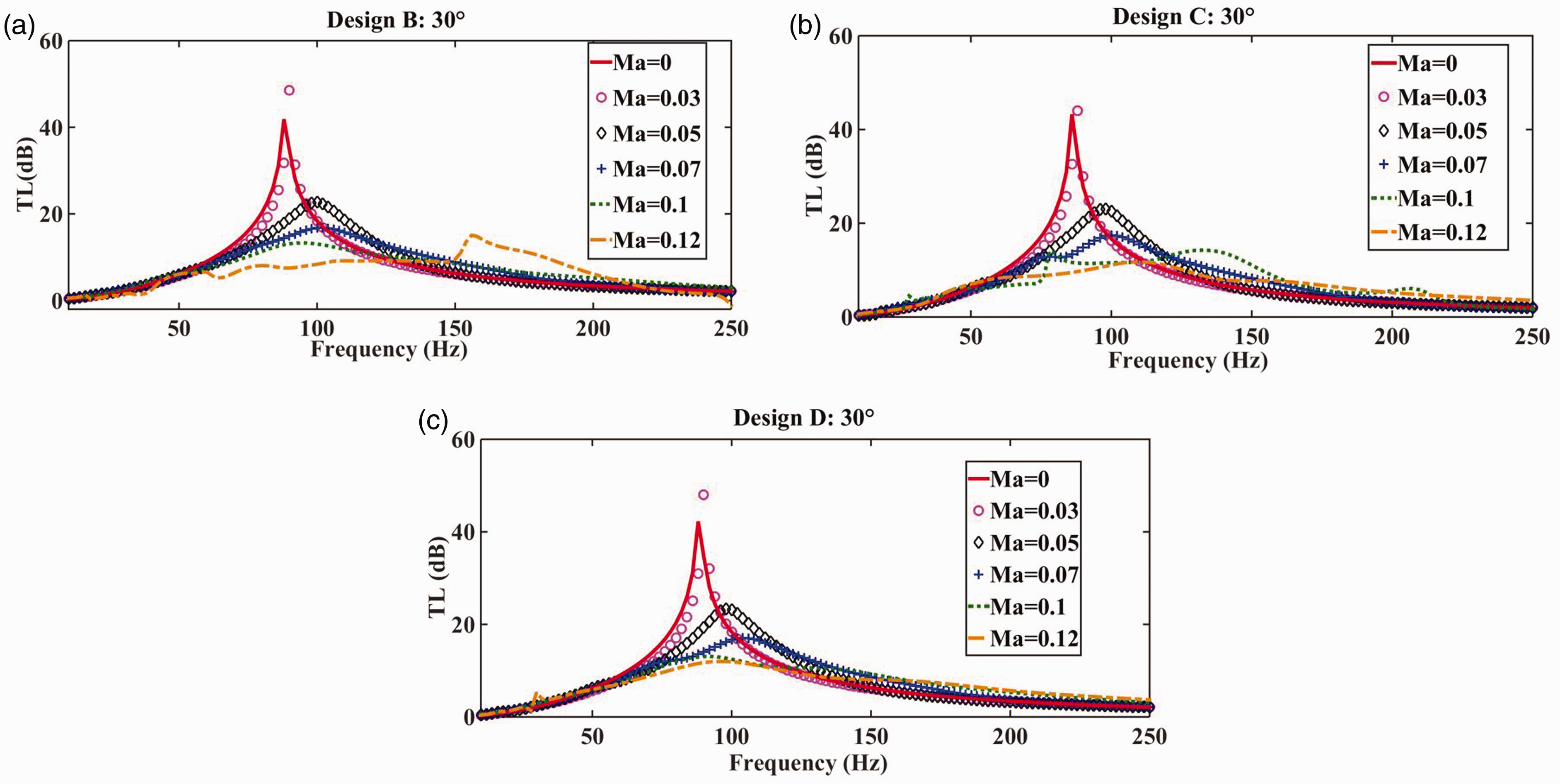
Variation of the maximum transmission loss (TLmax) of Designs B, C, and D, as the extended neck deflection angle is set to 30° and Ma is set to six different values.
Figure 8 illustrates the variation of the transmission losses of Designs B, C, and D with the forcing frequency, as the extended neck deflection angle α is set to 45° and Ma is set to six different values. It is apparent that the maximum transmission loss is decreased, as Ma is increased from 0 to 0.12. Furthermore, Design B has two transmission loss peaks at 119 Hz and 180 Hz. This means that it has a better noise damping performance than Design C and Design D, as Ma = 0.1 and
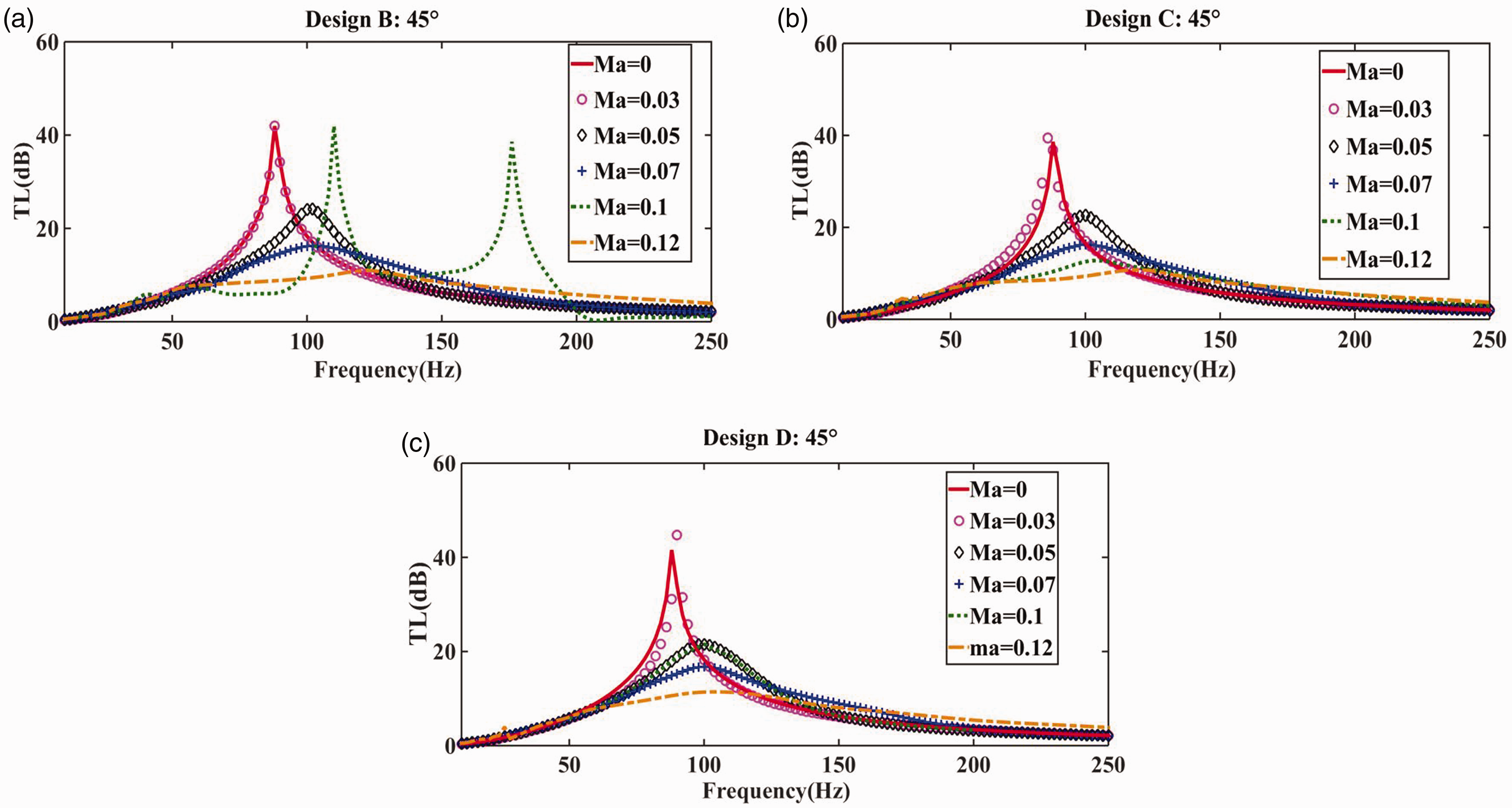
Variation of the maximum transmission loss (TLmax) of Designs B, C, and D, as the extended neck deflection angle α is set to 45°, and Ma is set to six different values.
Table 2 summarizes the maximum transmission loss, i.e. TLmax corresponding to three different designs. It can be seen that Designs B and C are involved with a higher TL peak at Ma = 0.1 than those at Ma = 0.07 and Ma = 0.12. This indicates the proposed Helmholtz resonators with extended necks with a deflected angle have better aeroacoustics attenuation performance at Ma = 0.1 than at Ma = 0.07 and Ma = 0.12 in most cases. Furthermore, the proposed Helmholtz resonators have a better transmission loss peaks at low Mach number. However, Design B has the highest transmission loss peaks at Ma = 0.1 than Design C and Design D at six different Mach numbers. In addition, Design B has a better overall noise damping performance than Design C and Design D.
A summary of the maximum transmission loss corresponding to different designs.
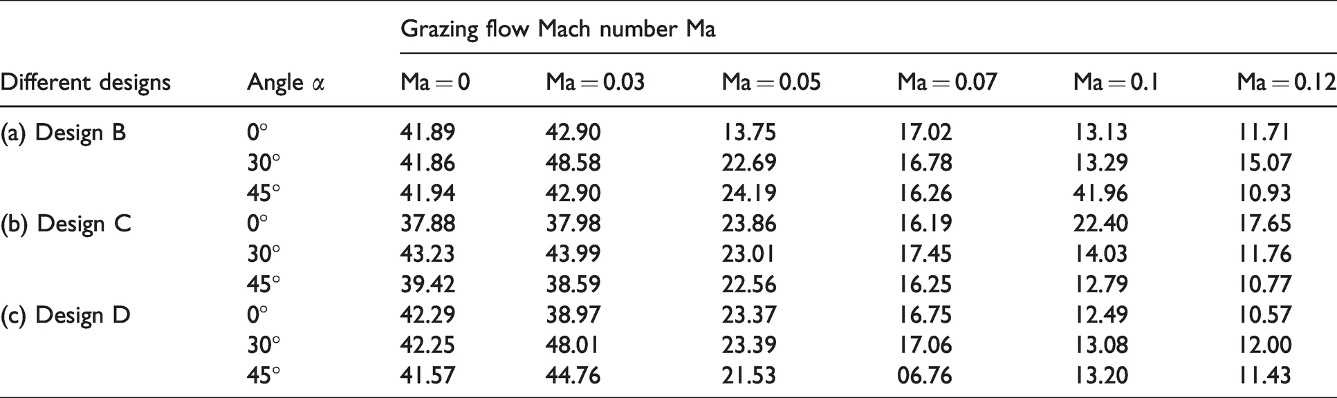
Figure 9 shows the variation of the transmission losses of Design A, B and C over the forcing frequency range, as the Ma is set to 0.1 and the extended neck deflection angle α is set to 30° and 45°. Figure 9(a) shows that some modified Helmholtz resonators have higher TLmax and resonant frequency than Design A, which means these modified Helmholtz resonators have better noise attenuation performance than Design A. It can be found from Figure 9(b) that the transmission loss has a negative value of approximately −1 dB at the 205–210 Hz frequency range. The negative transmission loss under the condition of high Mach number means that the modified Helmholtz resonator generates noise, instead of damping it.
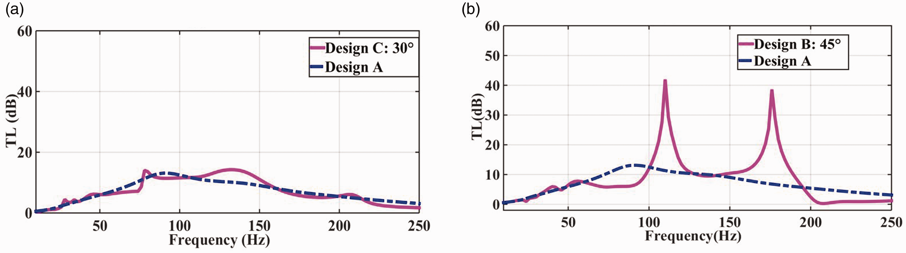
Variation of the transmission losses (TL) of Design A, B and C with forcing frequency range, as the Mach number is set to 0.1 and the extended neck deflection angle is 30° and 45°.
Variation in resonant frequencies with different grazing flow Mach numbers for different designs and angles is shown in Figure 10. It can be seen that the resonant frequencies increase as the grazing flow Mach number is increased. This indicates that these modified Helmholtz resonators can broaden the noise damping frequency band. In most cases, Ma = 0.1 and Ma = 0.12 have higher resonant frequency peaks and a broader frequency bands than other Mach numbers. Furthermore, the overall resonant frequency peaks of Design C are higher than that of Design B and Design D. In addition, as
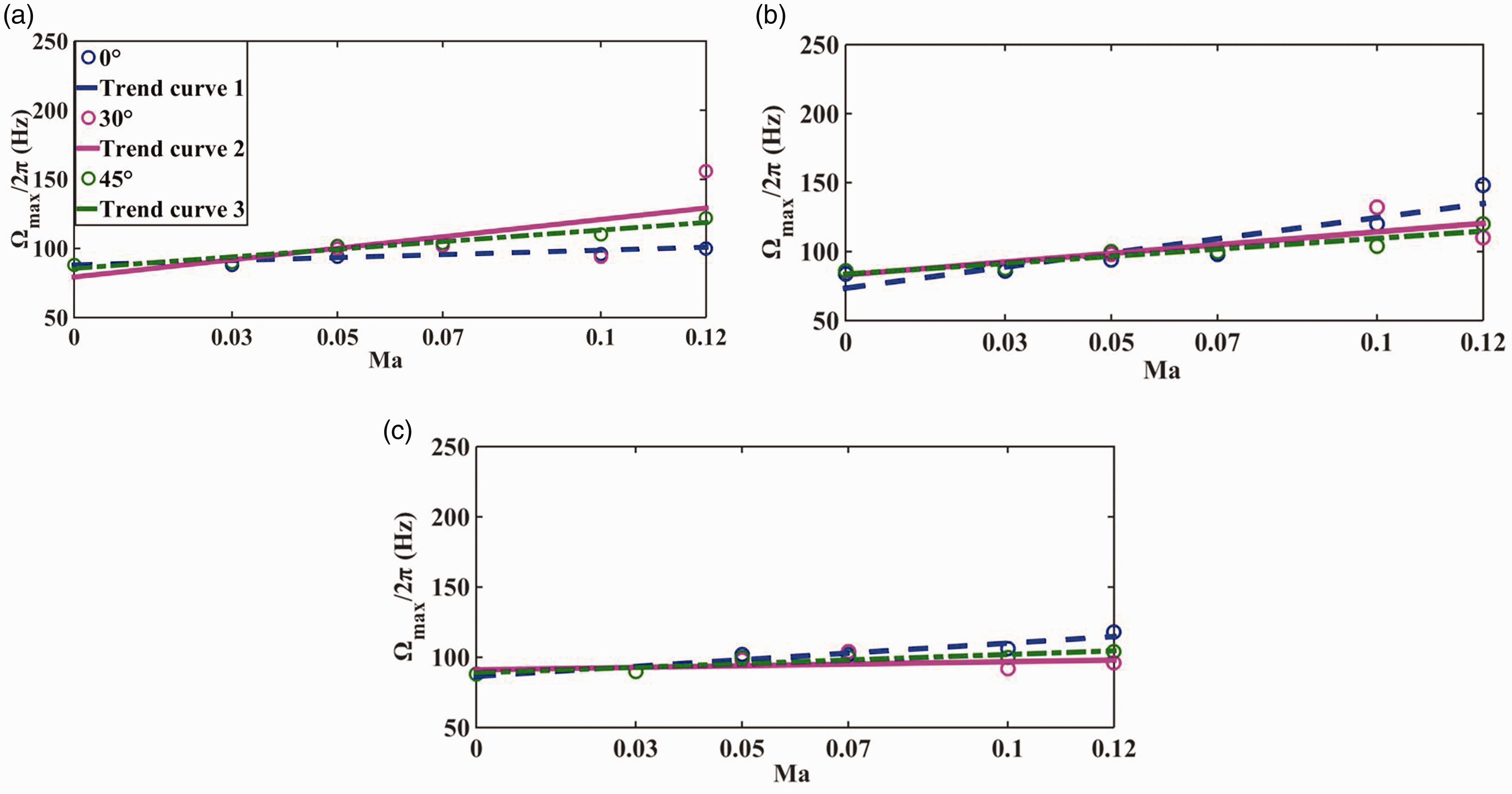
Variation in resonant frequencies with different grazing flow Mach numbers for different designs and angles. (a) Design B (b) Design C (c) Design D.
Effect of the deflection angle α
Figure 11(a) shows the variation of the transmission loss with forcing frequency of the Design B, as the deflection angle α is set to 0°, 30°, and 45° at Ma = 0.05. It can be found that for Design B, α = 30° and α = 45° have a larger transmission loss performance than α = 0°. This means that the deflection angle α affects the noise damping performances. Furthermore, for Design B, α = 30° and α = 45° have higher resonant frequencies than α = 0°, as shown in Figure 11(a). Figure 11(b) shows the transmission loss performances of Design B and Design A. The deflection angle of α = 48.32° is the maximum angle of the Design B, when the extended neck is touching the inner sidewall of the resonator cavity. Design B has a much larger TLmax and a higher resonant frequency than those of Design A. This indicates that Design B works more effectively over certain frequency ranges than Design A.
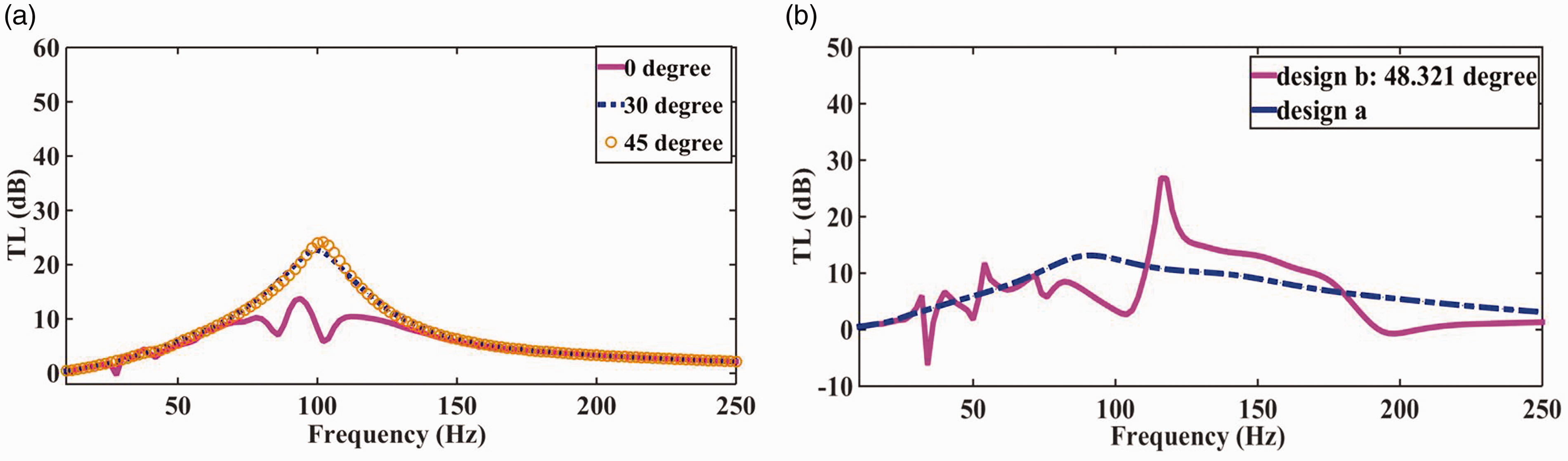
(a) Variation of the transmission loss between 0°, 30°, and 45° of Design B at Ma = 0.05. (b) Variation of transmission loss performance between Design B at 48.321° with Design A, as Ma = 0.1.
Figure 12 shows the comparison of the resonant frequencies of the proposed three designs with different deflection angle α in the absence of a grazing flow Mach number. It can be seen that α = 30° has a higher maximum resonant frequency than α = 0° and α = 45°. For Design D, α = 0° and α = 45° have a higher maximum resonant frequency than α = 30°. In addition, for Design C, α = 0° and α = 30° have higher maximum resonant frequencies than α = 45°. However, for Design B, 30° have higher maximum resonant frequencies than α = 0° and α = 45°.
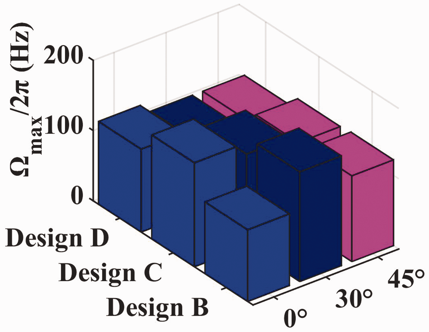
Variation in the resonant frequencies of different resonator designs and deflection angle α without considering the grazing flow Mach number.
To gain insights on the acoustic damping mechanism, the contours of acoustic pressure at different resonant frequencies are determined and shown in Figure 13. It can be seen that at the resonant frequency, vortex shedding is generated at the neck area. 19 However, there are no clear observations on the flow filed such as velocity and vorticity in the resonator cavity.
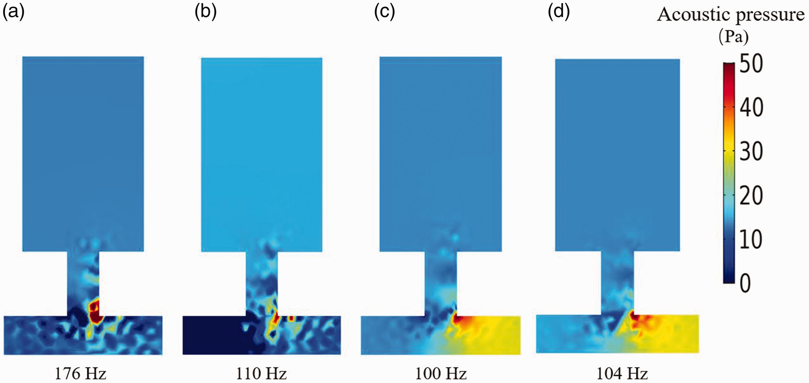
Contours of acoustic pressure at their resonant frequencies. (a) Design B: Ma = 0.1,
Figure 14 shows the comparison of the velocity and vorticity contours of Design A and Designs B-D at Ma = 0.1 and α = 45°. A clock-wise flow circulation zone is created in all designs. In addition, the extended neck (e.g. the extended neck of Design B or Design C or Design D) affects the vortex shedding intensity and distributions. However, these contours of Design A and Design D has little difference. The shear separations are also different. This may due to the fact that non-slip boundary conditions hold on the neck surface.
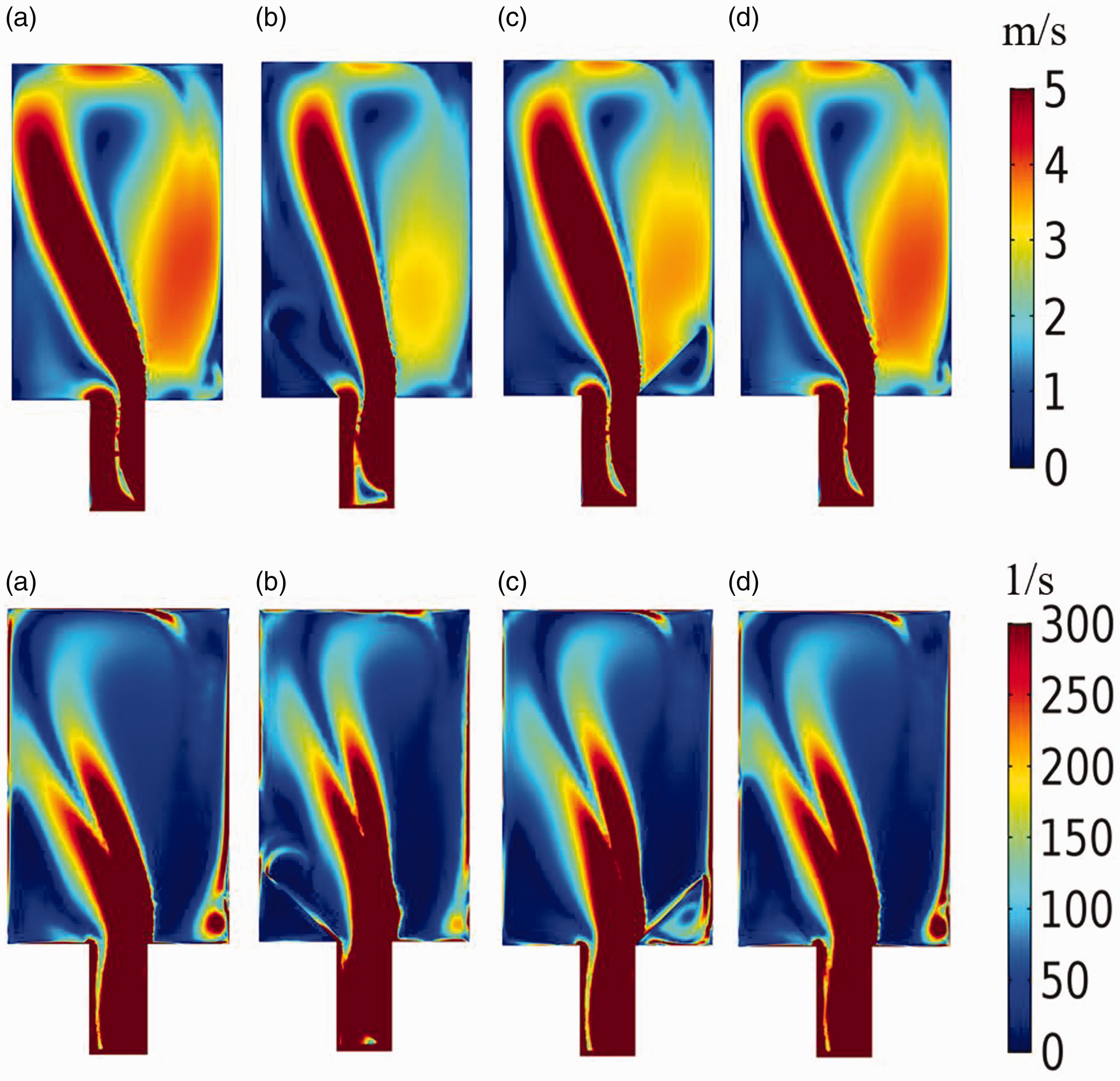
Comparison of the velocity and vorticity contours Design A and Designs B–D at Ma = 0.1 and
Effect of the extended neck implementation configurations
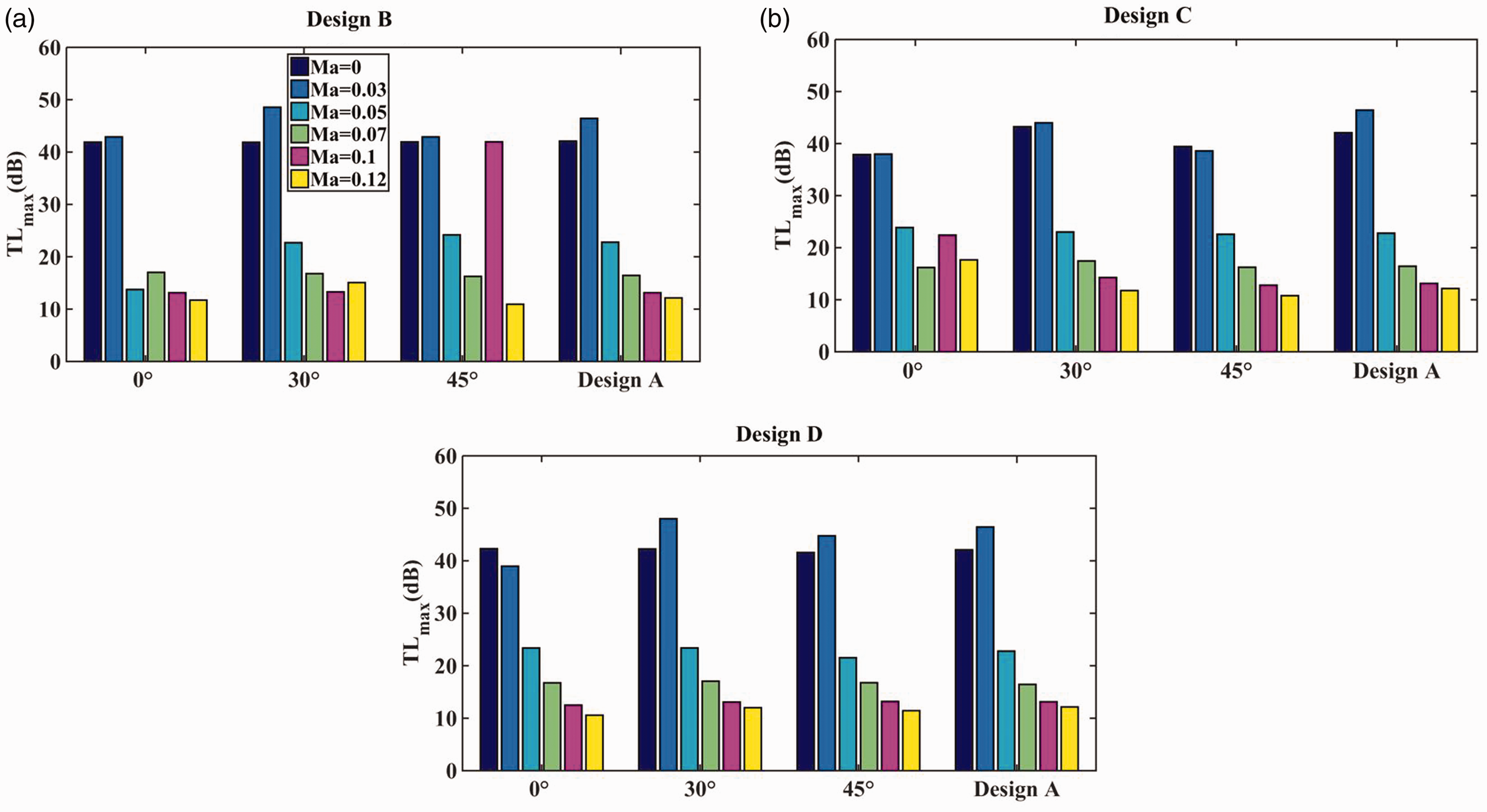
Figure 15 shows the comparison of the maximum transmission loss with different designs and deflected angles, as the grazing flow Mach number is set to six different values. It can be seen that the transmission loss peaks of Design B at six different Mach numbers are higher than those of Designs A and C in most cases, as summarized in Table 2 above. This is most likely due to the enhanced thermos-viscous effect and resonance effect (see Figures 14(b) and 13(a)) resulting from the implementation of the extended neck deflected to the upstream of the flow direction. When the extended neck deflected to the downstream of the flow direction, i.e. Design C, the resonance effect inside the cavity is almost unchanged (see Figure 14(c)) in comparison with no extended neck as illustrated in Figure 14(a).
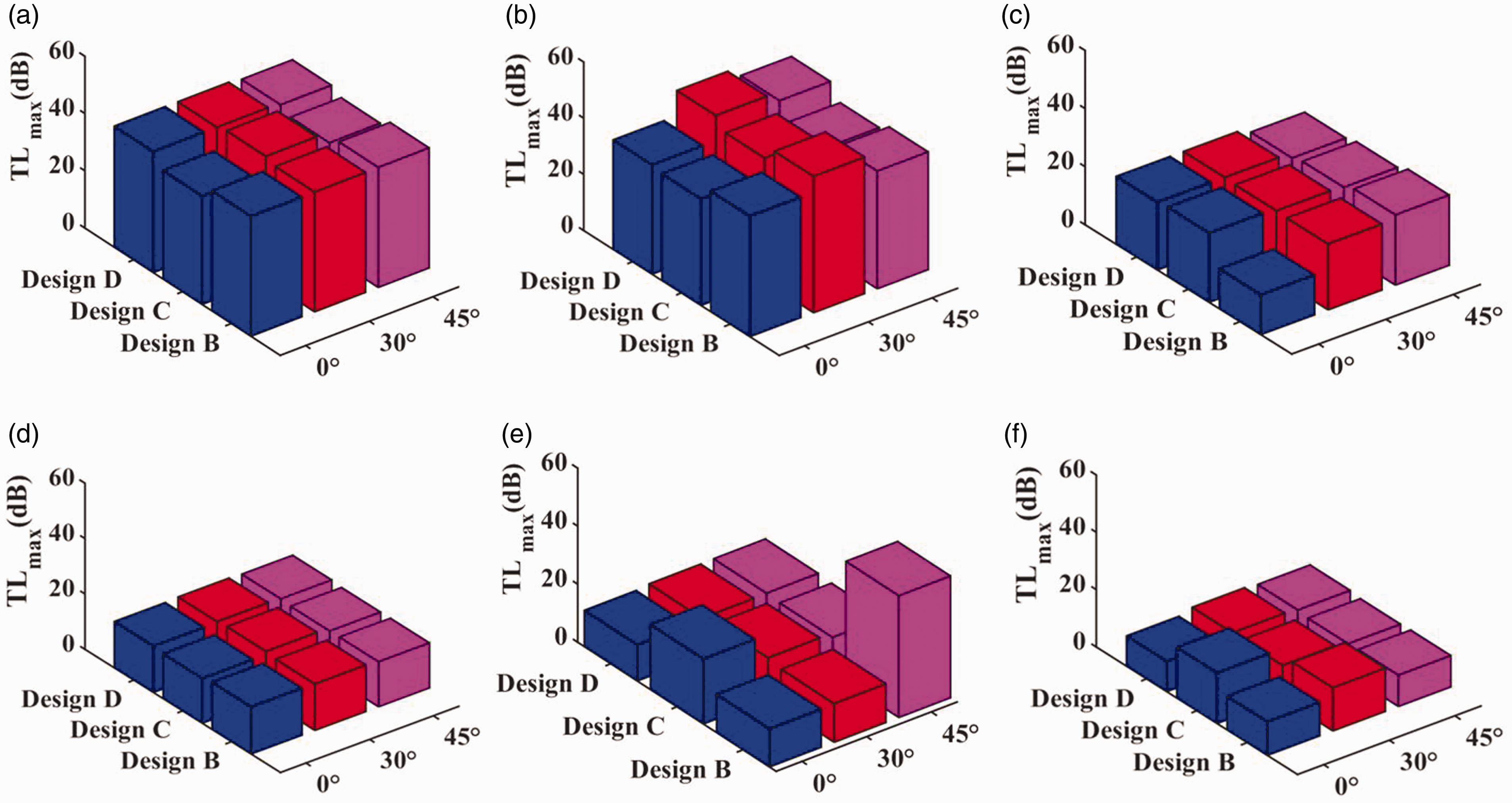
Variation of the maximum transmission loss (TLmax) with different designs and deflected angles, as the grazing flow Mach number is set to six different values. (a) Ma = 0, (b) Ma = 0.03, (c) Ma = 0.05, (d) Ma = 0.07, (e) Ma = 0.1 and (f) Ma = 0.12.
Note that the maximum TL may be slightly related to the frequency step being chosen. In practice, when real-time experimental tests are conducted to examine the noise damping performance over a broad frequency range, the frequency step is typically selected to be 2–10 Hz. A very small frequency step leads to a dramatic increase of experimental time and cost. In this work, we choose 2 Hz, and it is justified by comparing with the experimental data available. In addition, the TLmax is used to show the relative variation trend between the different designs under different tested conditions. It is only for comparison purpose. This discovery sheds a light on the design of new modified Helmholtz resonators for gas turbines.38–40
The resonant frequency
Discussion and conclusions
In this work, we attempt to numerically study and optimize modified designs of a Helmholtz resonator with an extended neck to improve its noise damping capacity for industrial application in engine systems. For this, a two-dimensional numerical model of a duct with a Helmholtz resonator with an extended neck was developed in the frequency domain. It is applied to predict its transmission loss performance, as a grazing flow is present. The model was first validated by comparing the present results with the experimental results reported in the literature. The model was then applied to study the aeroacoustics attenuation performance of the unconventional Helmholtz resonators with extended necks. Emphases are placed on the effects of (1) the grazing flow Mach number Ma, and (2) the deflected angle α between the extended neck and the y-axis, and (3) the extended neck 49 implementation configurations. The key research findings are: The Helmholtz resonator with an extended neck contributes to the resonant frequency shift in comparison with the conventional Helmholtz resonator (i.e. no extended neck). Its maximum transmission loss is also different from that of the conventional Helmholtz resonator. In most studied cases, as the grazing flow Mach number is set to Ma=0.03, the maximum transmission loss ( When Ma > 0.07, As Ma is increased, the resonant frequency of the proposed Helmholtz resonators with an extended neck is increased in general. In addition, two or three transmission loss peaks are observed at higher frequency range. This means that the unconventional resonators with extended necks are associated with a more broad frequency range. The deflection angle α of the extended neck relative to the y-axis is found to affect the transmission loss of the proposed Helmholtz resonators. When Ma≤0.03, there is no observed clear difference between TL of the conventional Helmholtz resonators with upstream and/or downstream deflected neck, no matter what α is set to. However, as Ma is non-negligible, Helmholtz resonator with a upstream extended neck is found to involve with a larger It is found that as α=45° and Ma=0.1, Design B and Design C have a better transmission loss performance than Design A, as Ma=0.1 or Ma=0.12. Design B has a broader frequency range than that of Design C and Design D, especially when α=30° or α= 45°. A Helmholtz resonator with an extended neck could generate additional noise, i.e. involving with a negative transmission loss at higher Ma, especially when α=30° or 45°. This means that the extended neck contributes to the‘whistling’phenomenon. The classical formula
Footnotes
Acknowledgements
The authors would like to thank Jiangsu University of Science and Technology for the scholarship.
Declaration of conflicting interests
The author(s) declared no potential conflicts of interest with respect to the research, authorship, and/or publication of this article.
Funding
The author(s) received no financial support for the research, authorship, and/or publication of this article.