
Abstract
As a typical noise-attenuating device, Helmholtz resonators are widely implemented in aero-engines and gas turbines to decrease the transmission of acoustic noise. However, an asymmetric Helmholtz resonator could be designed and implemented due to the limited space available in the engines. To examine and optimize the noise-attenuating performances of the asymmetric resonator, comparison studies are performed. For this, a two-dimensional frequency-domain model of a cylindrical duct with a grazing flow is developed. An asymmetric Helmholtz resonator is attached as a side branch. The model containing the linearized Navier–Stokes equations is validated first by comparing the predicted results with the experimental ones available in the literature. Further validation is conducted by comparing the results of an asymmetric resonator with the analytical ones available in the literature. The effects of (1) neck offset distance from the center of the resonator cavity denoted by
Introduction
Undesirable tonal or broadband acoustic noise is present in aero-engines or gas turbine engines.1–5 To dissipate this noise, Helmholtz resonators are widely implemented in the engine systems.6,7 In practical engines, a Helmholtz resonator may be attached to a combustor to dampen thermoacoustic instability, 8 as a grazing flow is present. Such instability is characterized by periodic acoustic pressure perturbations; its amplitude may be up to 5–15% of the engine mean pressure. To mitigate these acoustic fluctuations,9–12 Helmholtz resonators are designed and implemented. With these resonators implemented, acoustic pulsations may be attenuated somehow and small-amplitude acoustic perturbations are acceptable in engines to increase the fuel–air mixing. A typical Helmholtz resonator 13 consists of a large cavity, inside which the fluid could be resonated at certain frequencies (also known as resonant frequencies). The resonator and the combustor are connected via a “neck” (a short tube). Acoustic perturbations propagating to the resonator could excite its neck mass—the fluid in the cavity to “resonate.” The resonant frequency is strongly related to the resonator’s geometry and its dimensions (such as the neck and cavity). Thus, such resonance leads to noise absorption being achievable through the effects of thermoviscous (linear) and vortices (nonlinear) generation and shedding. 14 These are the dominant noise-attenuating mechanisms of symmetric 15 or asymmetric Helmholtz resonators.
Intensive studies and researches have been performed on Helmholtz resonators8,16 with the aim of shedding light on the design, practical implementation, and performance characterization such as power absorption coefficients, acoustic impedance, transmission loss (TL). A nonlinear Helmholtz resonator model (similar to the one proposed by Cummings 17 ) was derived by Bellucci et al. 8 to estimate its power absorption coefficient and acoustic impedance, and to characterize the nonlinear vorticity-involved attenuating physics. Validation of this model was done by comparing with the experimental results from an acoustic duct without a grazing flow. Attaching a Helmholtz resonator to an engine leads to a large acoustic impedance at its resonant frequency to acoustic pressure disturbances propagating and thus a great TL, since these sound waves could be completely blocked. However, the resonant frequencies of Helmholtz resonators are distributed over certain frequency bands only. Thus, the resonator’s effectiveness is restricted and limited. 18 To optimize the resonator’s damping performance over a broader frequency range, actively passive control of Helmholtz resonators was recently proposed. This optimization is achievable due to the fact that the resonant frequency depends strongly on its geometric dimensions, 7 such as the length and cross-sectional area of the neck. In a practical engine system,19–22 there is a mean fluid flow present, also known as grazing flow. Propagating sound waves could lead to unsteady vortices shedding at the neck edge. These vorticities are then “convected away” with the mean flow. However, they act as a sound source near the upstream edge.
The resonant frequency of a given Helmholtz resonator was theoretically derived many years ago. However, the vorticity-involved noise-attenuating physics and mechanisms are not completely understood, especially when there is a grazing mean flow 23 (tangential “hot” or “cold” flow over the resonator neck). Some experimental attempts were made 14 to visualize and to measure the noise damping mechanism and the performance of a Helmholtz resonator, as a hot grazing mean flow is present. Both linear and nonlinear acoustic responses of the resonator were measured. Experimental measurements of a Helmholtz resonator response were conducted by Ghanadi et al. 23 in a subsonic wind tunnel, which is used to produce a grazing cold turbulent flow. The resonator geometry was found to play a critical role on determining the excitation levels of acoustic velocity and pressure. Numerical investigations were also performed. 24 For example, Dai 24 studied the excitation of a Helmholtz resonator by convected vorticities.
Helmholtz resonators can be designed into symmetric and asymmetric configurations. Selamet and his group members13,25–27 conducted a series of studies on circular resonators (either symmetric or asymmetric) via experimental measurements or theoretical/numerical simulations. It was worth noting that most of these studies, even when an asymmetric resonator was considered, were conducted, when there is no grazing mean flow. To increase the resonator’s damping effect, absorbing materials or perforated plates were inserted into the resonator neck. The overall damping performance was compared with those without insertions. In addition, modified designs of a Helmholtz resonator were proposed by extending its neck into its cavity. The extended neck was theoretically and numerically shown to affect both the TL and the resonance frequency. To validate this finding, an impedance tube was applied to conduct experimental measurements. The numerical and theoretical investigations were conducted by applying boundary element method and piston-driven model. However, these numerical and theoretical studies are quite challenging to capture vorticity-involved damping mechanisms and difficult to examine the grazing flow role. This motivated partially the present study.
Foregoing researches and studies show that the acoustic noise-attenuating performance and vorticity-involved physics of symmetric or asymmetric Helmholtz resonators were studied by time- or frequency-domain modeling via solving nonlinear Navier–Stokes equations 28 or performing laser-involved flow visualization experiments. Such experimental and numerical investigations are time consuming and costly. To decrease the computational time and cost, and to determine the noise-attenuating performance and vorticity-involved physics of an asymmetric Helmholtz resonator with a grazing flow present, computationally efficient numerical models are necessary. To the maximum knowledge of the present authors, there are few experimental and numerical studies discussed in the literature. This motivated partially the present study.
In this work, a 2D numerical model is developed by considering the linearized Navier–Stokes equations. The model is built in a frequency domain and it can be used to evaluate the noise-attenuating performances of asymmetric Helmholtz resonators with a grazing flow present. The conventional symmetric resonator design is chosen to be a benchmark/reference configuration. The asymmetric configuration is associated with an offset neck. The developed 2D model is first validated by comparing with the experimental data available in the literature. Further validation is conducted by comparing with 3D analytical results of an asymmetric resonator available in the literature. The present paper is organized as follows. In the following section, the 2D frequency-domain model with governing linearized Navier–Stokes equations is built. In “Results and discussion” section, the calculated results from the present model are presented and compared with the analytical and experimental ones. The effects of (1) the grazing flow Mach number and (2) the asymmetry on the noise-attenuating performances are evaluated over the frequency range of 50–200 Hz. Finally, the key findings on the asymmetric Helmholtz resonator are discussed and summarized in the “Conclusions” section.
Description of the numerical model
The current work is concerned with a cylindrical duct with an asymmetric Helmholtz resonator implemented as schematically illustrated in Figure 1. The asymmetry is characterized by the neck offset distance
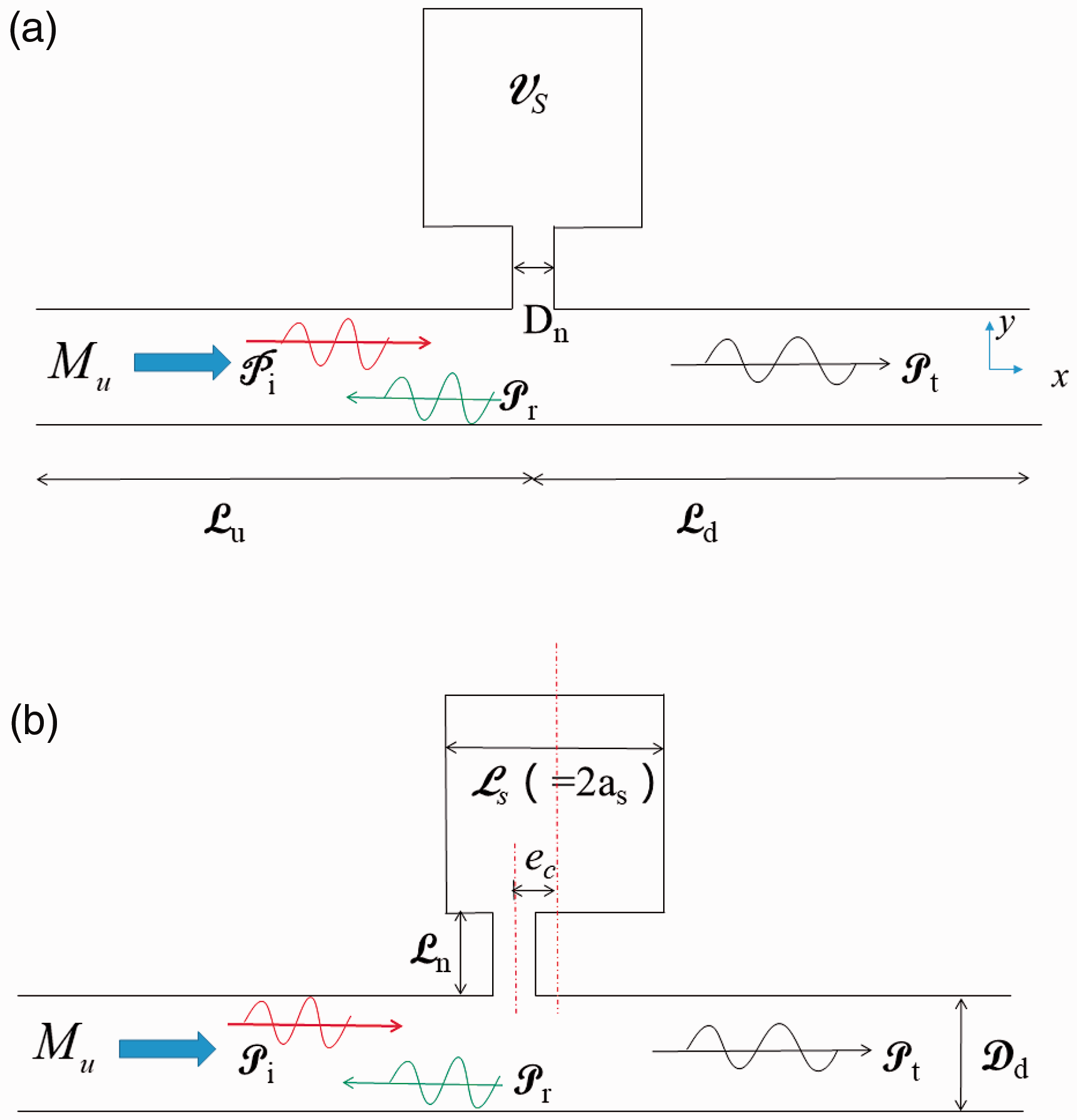
Schematic drawing of the modeled cylindrical duct with (a) a conventional symmetric and (b) an asymmetric Helmholtz resonator attached.
The 2D model is built by solving the linearized Navier–Stokes equations for incompressible and viscous air flow at low Mach number. The governing equations include mass, momentum, and energy conservation ones in a Cartesian coordinate system as given as

The momentum conservation holds as

The energy conservation holds as
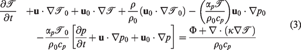
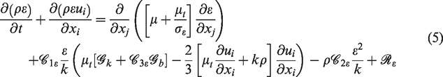
Turbulent motion leads to Reynolds stress, which is related to the fluctuating velocities’ cross-product terms. Thus, there is a need to model the turbulence. In the literature, there are various turbulence models such as Reynolds stress, eddy viscosity, large eddy simulation models to select. For simplicity, the current study chooses
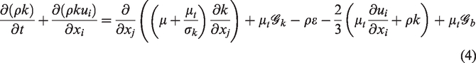
where
Dimensions, geometry, and mesh
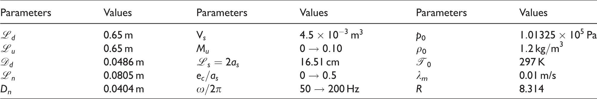
The geometry and dimensions of the modeled cylindrical duct in the presence of the mean flow and with the asymmetric Helmholtz resonator attached are summarized in Table 1.
Geometric dimensions of the cylindrical duct with a mean flow present and an asymmetric Helmholtz resonator implemented.
The mesh of the computational duct model is shown in Figure 2. To obtain an appropriate resolution of the vortices shedded and the shear layer at the neck–duct connected regions, a fine mesh with a total of 803,482 cells is chosen by conducting mesh independent study. The selected mesh is justified by validating the predicted results from the present model in comparison with the experimental and analytical results available in the literature, as discussed in the following section. By following initial trials, the time step is set to
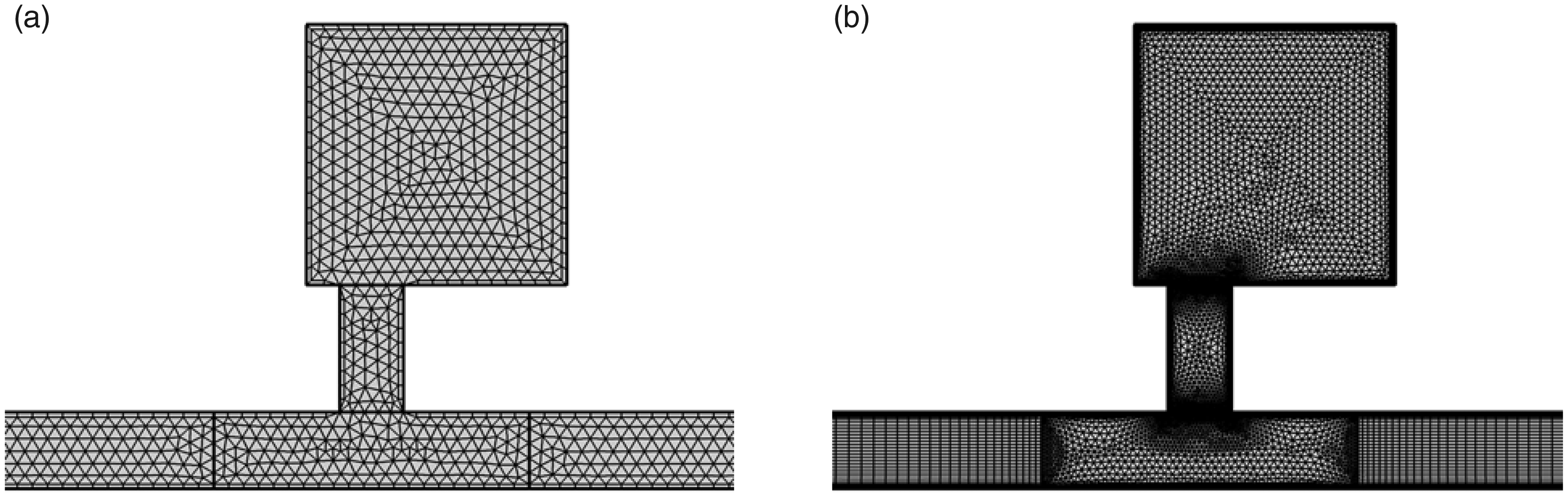
Computational unstructured mesh of the 2D model near the asymmetric resonator attached regions. (a) 634,956 cells and (b) 803,482 cells.
As plane waves are travelling along the duct with the asymmetric resonator implemented,both boundary conditions of the duct inlet and outlet are assumed to satisfy perfectly matched layer. The
where
Model validation
The linearized NS equations with the
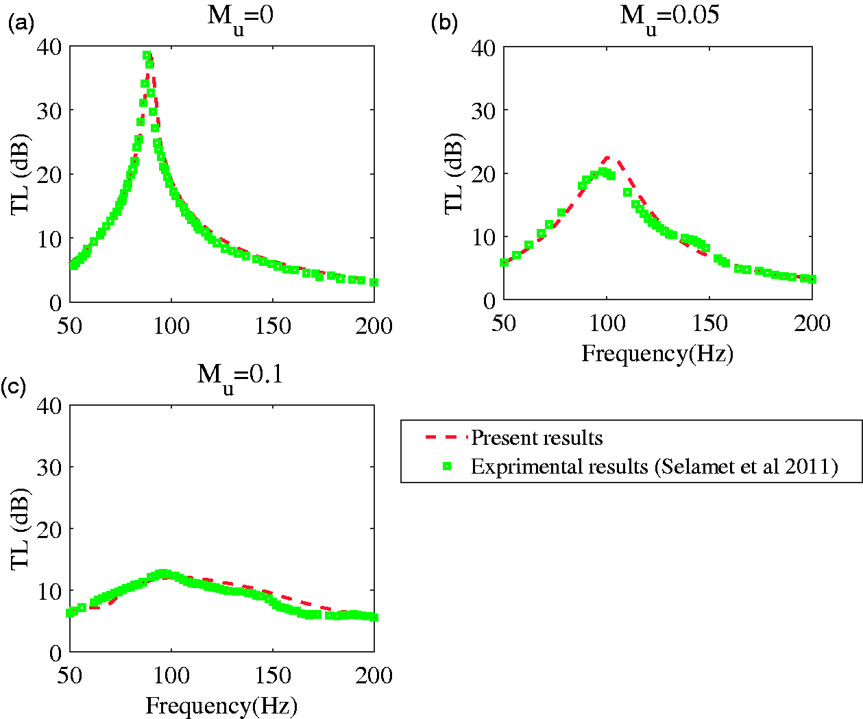
Validation of the numerical model by comparing the predicted results with the experimental ones available in Selamet et al.,
27
as Mu is set to three different values and
Further validation is conducted by considering the asymmetric Helmholtz resonator studied by Selamet and Ji.
26
Figure 4 shows the comparison of the present predictions and the 3D theoretical results obtained by Selamet and Ji,
26
as there is no grazing flow but the neck offset distance
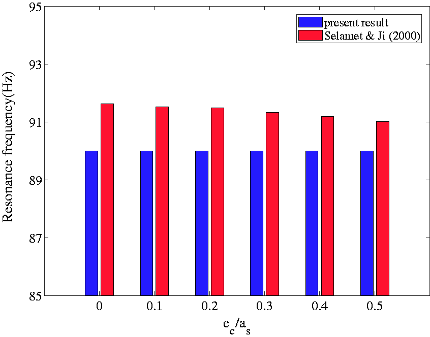
Validation of the numerical model by comparing the predicted results with the 3D theoretical ones available in the Selamet and Ji,
26
as
Results and discussion
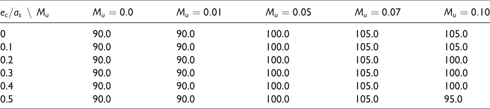
The numerical model is revised further to study the noise damping effect of asymmetric Helmholtz resonators in the presence of a nonnegligible grazing flow. The effect of the grazing flow is evaluated and shown in Figure 5. It can be seen that the maximum TL 31 is decreased from 39 to 11 dB by approximately 28 dB, as the grazing flow Mach number is increased from 0 to 0.10, as the neck offset distance is set to five different values. The resonant frequency corresponding to the maximum TL is found to shift by approximately 10% to higher values with increased Mu but less than 0.07. Further increasing Mu is shown to give rise to the resonant frequency being reduced. Table 2 summarizes the resonant frequencies of the asymmetric resonator corresponding to the maximum TL.
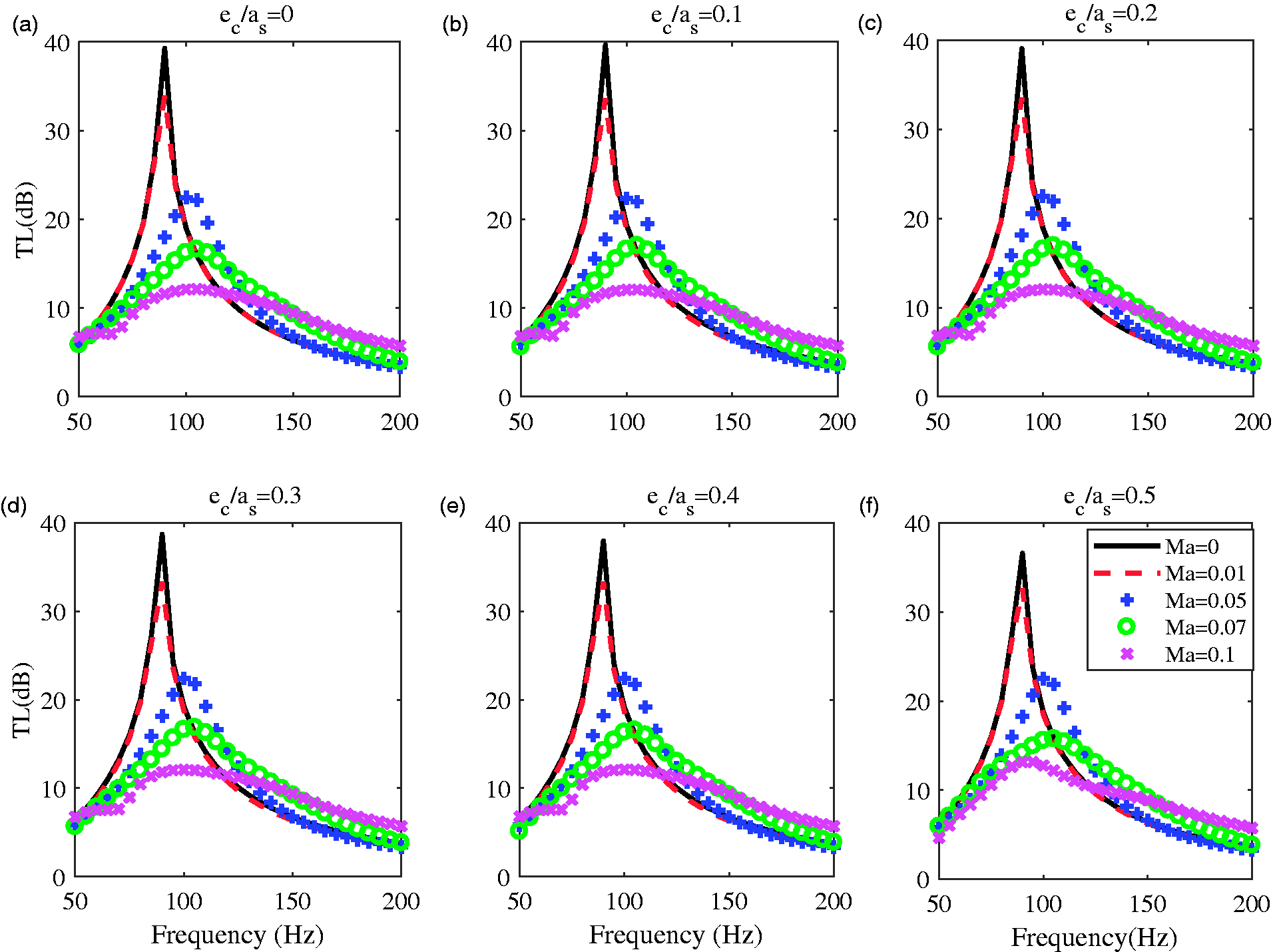
Variation of the TL with the forcing frequency, as the grazing flow Mach number is set to five different values. (a)
A summary of the resonant frequency of the asymmetric Helmholtz resonator corresponding to the maximum transmission loss, as
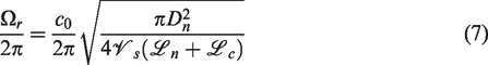
The resonant frequency Ω
r
of the asymmetric Helmholtz resonator could also be predicted by using the classical formula as
To shed lights on the TL and to gain insights on the vortex shedding and shear layer separation near the neck surface, Figure 6 illustrates the 2D contours of vorticity and velocity, as
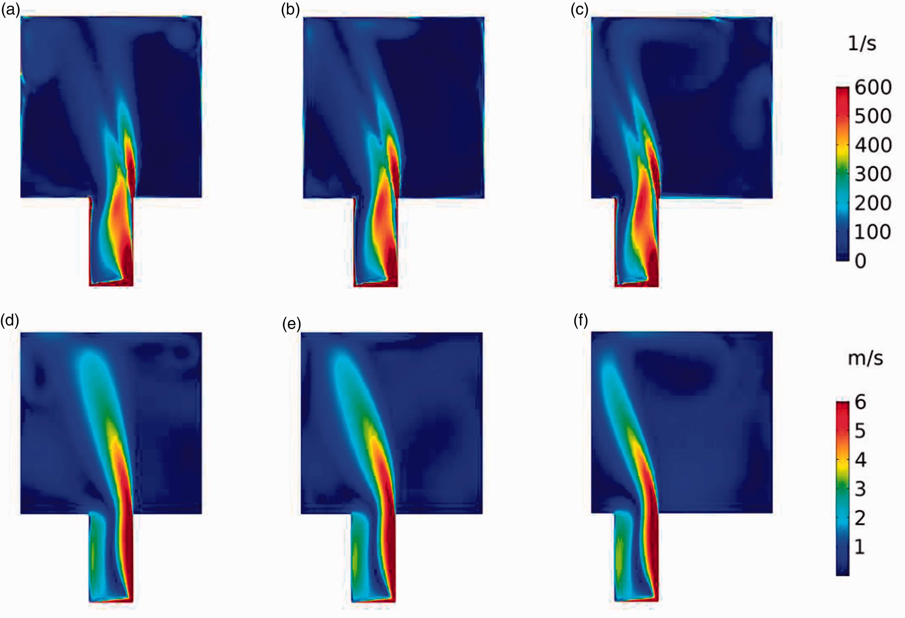
Comparison of the vorticity (a)–(c) and velocity (d)–(f) contours near the offset neck, as
The effect of asymmetry, i.e. the neck offset distance
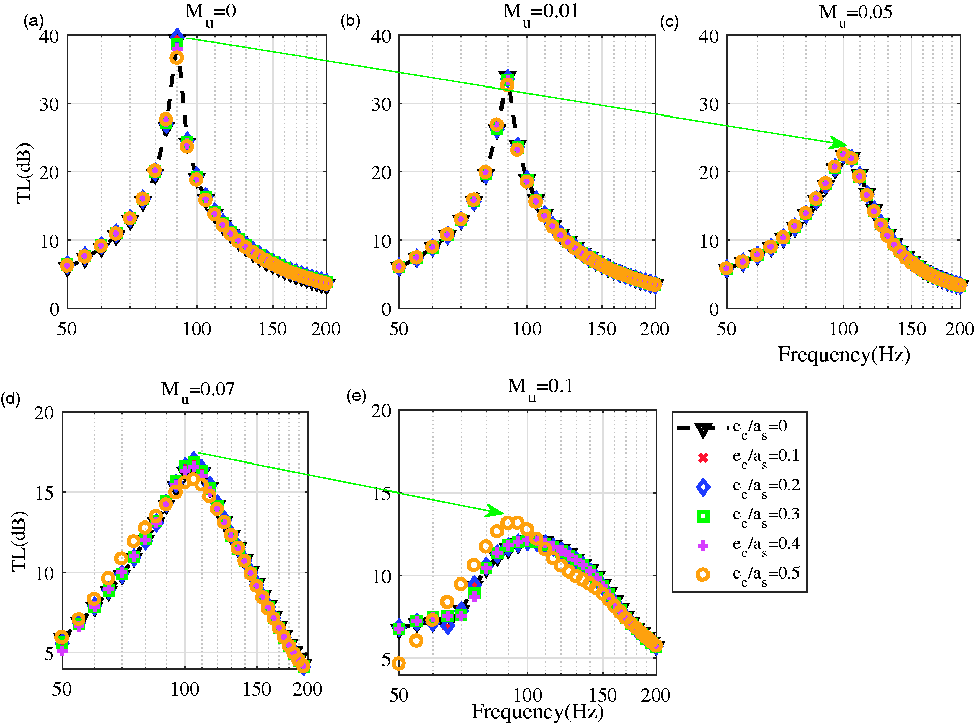
Variation of the TL of the asymmetric resonator with the forcing frequency, as the neck offset distance
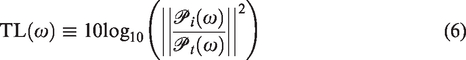
The maximum
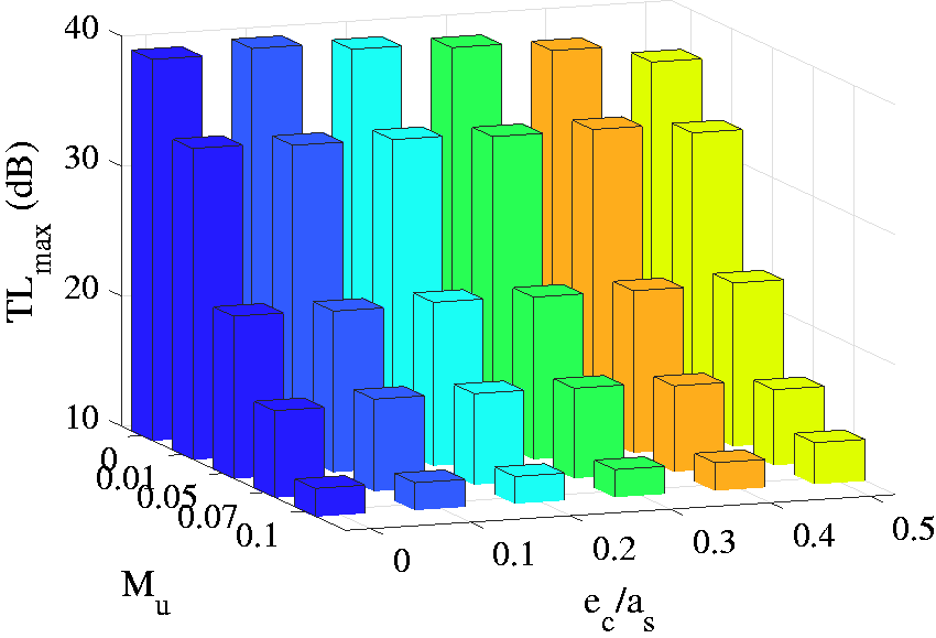
Variation of the maximum TLs of the asymmetric resonator with the Mach number Mu and
Conclusions
In the present study, 2D numerical model of a cylindrical duct with an asymmetric Helmholtz resonator attached is developed in frequency domain and applied to predict its TL performance. The asymmetry effect is examined by considering five different neck offset distances from the center of the resonator cavity denoted by As the grazing flow Mach number Mu is small ( Increasing the grazing flow Mach number leads to the maximum TL being reduced by more than 60% (see Figure 7(a) and (e)). The mean grazing flow, in general, gives rise to a weaker interaction between the asymmetric resonator cavity and the main pipe. Thus, it results in the resonant frequencies to higher values but a reduced maximum TL. The classical formula Intensity of vortex shedding is increased near the edge of the offset neck, as Mu is increased. This reveals the increased shear separation on the surface of the neck. This leads to the diminished capacity of the resonator for attenuating unwanted noise at higher grazing flow velocities.
In summary, the asymmetric Helmholtz resonator is numerically studied, with the overall aim of increasing its noise-attenuating performance to enable it being implemented in engine combustors.37–42
Footnotes
Declaration of conflicting interests
The author(s) declared no potential conflicts of interest with respect to the research, authorship, and/or publication of this article.
Funding
The author(s) disclosed receipt of the following financial support for the research, authorship, and/ or publication of this article: This work is supported by the National Natural Science Foundation of China with grant nos. 51506079 and 11661141020. This financial support is gratefully acknowledged.