
Abstract
Low-frequency noise has a long wavelength, decays very slowly, and is extremely penetrating. Traditional marine acoustic insulation materials have difficulty achieving effective control of this low-frequency noise. In this paper, a series-parallel arrangement structure of a low-frequency metamaterial is designed, which mainly comprises convoluted channels and Helmholtz cavities in series and a sandwich arrangement of multiple cells (as opposed to the traditional parallel arrangement). We use a numerical method to establish an acoustic-solid coupling model for the metamaterial, consider the influence of thermal and viscous losses on its sound absorption performance, and investigate the sound absorption characteristics and mechanisms of the single-cell and multicell structures. The metamaterial designed in this paper shows an average absorption coefficient of 0.97 in the range of 130–145 Hz. An experimental model was prepared by 3D printing, and the intended sound absorption effect was experimentally verified.
Keywords
Introduction
The low-frequency noise generated during the operation of machinery and equipment such as airplanes, automobiles, and ships has a long wavelength and travels a long distance. Attenuation of this noise is limited by the law of quality of sound-insulating materials, and a sound-insulating material with a thickness comparable to that of the wavelength is required to effectively control the low-frequency noise.1,2 Acoustic metamaterial structures proposed in recent years break the limitation of the law of mass action and offer subwavelength sound absorption and insulation performance, which provides a new paradigm for low-frequency noise control.3,4
Researchers have recently proposed metamaterial structures with low-frequency acoustic insulation properties.5–8 In 2000, Liu first proposed the concept of acoustic metamaterials and designed an acoustic metamaterial with a negative energy density to achieve low-frequency sound insulation. 9 In 2006, Feng et al. proposed a one-dimensional Helmholtz resonance cavity acoustic metamaterial with a negative equivalent elastic modulus when the acoustic wave frequency was close to the resonant frequency of the structure, thus achieving structural sound absorption. 10 In 2015, Shi et al. proposed a Helmholtz cavity for which the length of the neck was increased by designing a helical neck to achieve low-frequency sound absorption. 11 In 2022, Vergara et al. designed a hybrid acoustic metamaterial consisting of a porous layer with a modified Helmholtz cavity for broadband sound absorption. 12 Therefore, the Helmholtz cavity structure with an optimized design can achieve effective control of low-frequency noise.
As early as 2012, Liang et al. first proposed the concept of coiled acoustic metamaterials with a Z-shaped coiled acoustic channel that greatly extended the acoustic propagation path and offered a high refractive index for acoustic waves. 13 In 2015, Cheng et al. proposed a highly symmetrical acoustic metamaterial with multiple Mie resonances, which provided total reflection of acoustic waves by generating a negative bulk modulus with a negative mass density at resonance. 14 In 2016, Li et al. designed an acoustic metamaterial by combining coiled channels with perforated plates, which achieved perfect sound absorption in the low-frequency range by matching the impedance based on the Helmholtz cavity and channel length. 15 In 2017, Krushynska et al. designed a coiled acoustic metamaterial based on a spider web structure to achieve low-frequency noise control. 16 In the same year, Liu et al. investigated the broadband tunability by varying the cross-sectional area of the coiled channel and achieved perfect sound absorption near 400 Hz. 17 In 2021, Almeida et al. enabled a metamaterial structure to have a sound absorption coefficient greater than 0.91 in the low-frequency range by increasing the number of symmetrically curled channels. 18 Coiled metamaterials can thus achieve remarkable sound absorption at a specific frequency by extending the sound propagation channel. However, ship noise presents the characteristics of a large broadband signal across multiple frequencies such that relying only on a single coiled channel for noise control is impractical. Therefore, an important issue for researchers has been to consider methods for achieving broadband sound absorption of this type of noise.
Due to the limited acoustic absorption band of single-cell structure acoustic metamaterials, some researchers have explored the design of multicell coupling of acoustic metamaterials.19–21 Chen designed a combination structure with two cavities arranged contiguously, where two absorption peaks appeared in the absorption band such that broadband sound absorption was achieved in the multicavity parallel structure. 22 Zhang et al. designed a six-cavity parallel combination structure that resulted in six perfect absorption peaks in the 100–180 Hz range. 23 Cui et al. combined a coiled channel structure with a Helmholtz cavity to design an 11-cell parallel structure that achieved an average sound absorption ratio of 0.6 in the range of 90–360 Hz. 24 Although such a large broadband sound absorption effect can be achieved by arranging multiple single-cell structures in parallel, the underlying multicell parallel design makes the resulting area too large and reduces the coupled sound absorption performance between cavities.
Therefore, a metamaterial structure based on a series-parallel arrangement is proposed here to improve the coupled acoustic performance of the multicell structure. Its acoustic properties and absorption mechanism are investigated by numerical and experimental methods. The proposed series-parallel arrangement structure reduces the acoustic surface area of the coupled multicell structure and achieves a broadband perfect sound absorption effect in the low-frequency range.
Metamaterial structure and sound absorption principle
Single-cell design
The metamaterial structure designed in this paper consists of four pinched parallel structures, each of which includes three tandem single cells arranged along the acoustic incidence direction. Each single-cell structure consists of a convoluted channel and a Helmholtz cavity in series. The structural combination and the dimensions of each layer are shown in Figure 1(a)–(f). The single-cell structure in Figure 1(a) contains seven layers, including three perforated plates, two convoluted channels, one Helmholtz cavity, and one closed plate. The length, width, and height of the single-cell structure are W = 40 mm, H = 40 mm, and L = 48.5 mm, respectively. Layers 1, 3, and 5 are perforated plates with thickness a = 2 mm, layers 2 and 4 are convoluted channels with thickness b = 6 mm, and layer 6 is a Helmholtz cavity with length c = 29.5 mm. The width of the channels is w = 3 mm, and the thickness of the inner wall is h = 0.5 mm. The perforations of the perforated plates in layers 1 and 5 are squares with side length d = 10 mm. The four perforations of the perforated plate in layer 3 are squares with side length e = 3 mm. The thickness of the closed plate at the bottom is t = 1 mm. The sound wave enters the two convoluted channels from the first perforated plate to extend the transmission path of the sound wave and finally enters the Helmholtz single cavity. Schematic diagram of the tandem single-cell structure with a convoluted channel and a Helmholtz cavity. (a) Tandem single-cell structure. (b) Tandem single-cell split structure. (c) Layers 1 and 5 perforated plates. (d) Convoluted channel. (e) Layer 3 perforated plate. (f) Helmholtz cavity outer wall.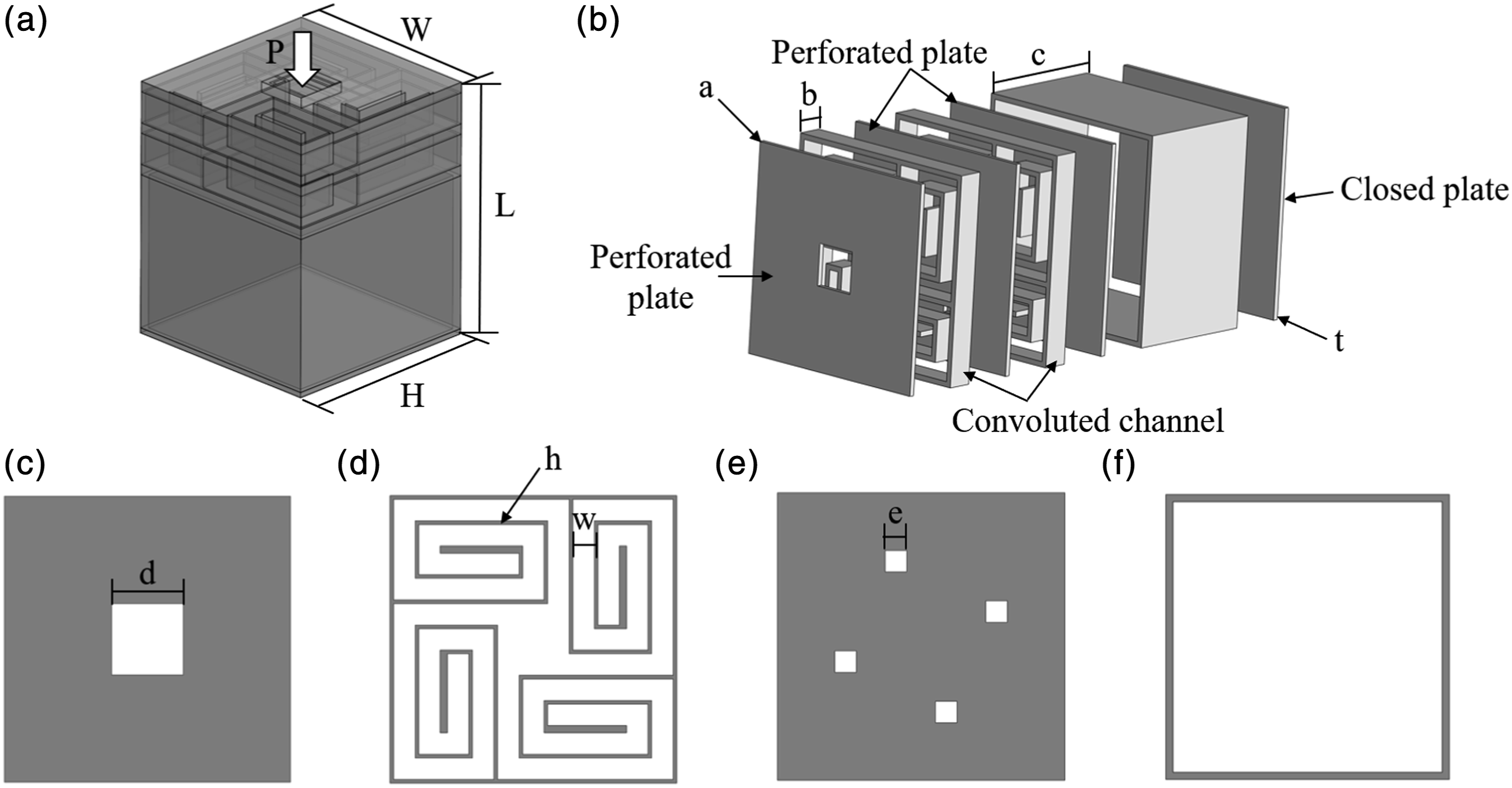
Principle of structural sound absorption
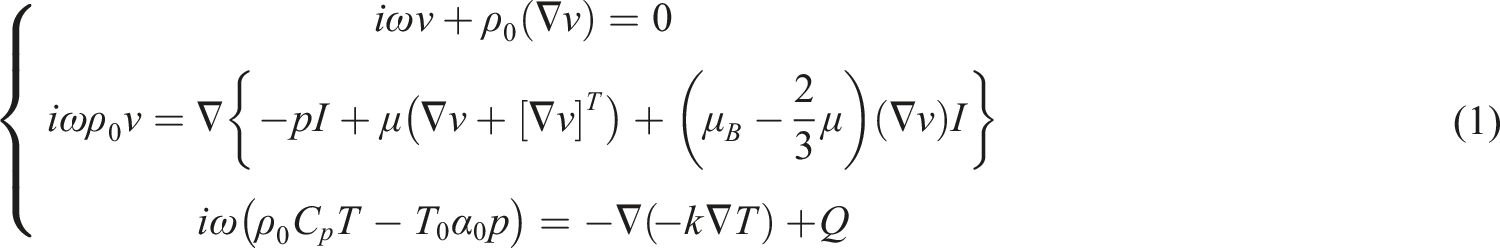
Thermal and viscous losses occur when an acoustic wave propagates inside a narrow and convoluted channel. Therefore, these effects need to be considered when simulating the proposed structure. The steady-state continuity equation, momentum equation, and energy conservation equation25,26 for the thermoviscous acoustics in the metamaterial structure of Figure 1 are shown in the set of equations (1)
In the above equations,
The relationship between the medium density, medium pressure, and temperature is shown in equation (2)

Combining equation (1) with equation (2), we can calculate the sound pressure
The acoustic impedance is the ratio of the sound pressure of a sound wave passing through a plane over the particle velocity through the interface. The expression for the acoustic impedance is given in equation (3)

When a sound wave is vertically incident on the surface of the metamaterial, the acoustic impedance

Combining equation (2) and equation (4) gives the formula for the absorption coefficient, as in equation (5)

For the Helmholtz single cavity in Figure 1, the air inside the cavity resonates when the acoustic wave reaches it through the convoluted channel. The air pressure sharply increases in amplitude due to the resonance, generating friction at the cavity opening, and the sound wave is converted from acoustic energy to thermal energy. The Helmholtz single-cavity resonant frequency
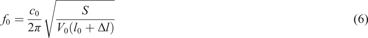
As seen from equation (6), the cavity resonant frequency depends on the cavity volume, cavity neck tube length, and cavity neck tube cross-sectional area. In the structure considered here, the neck tube length is equivalent to the convoluted channel length in Figure 1, and the neck tube cross-sectional area is equivalent to the convoluted channel width in Figure 1. Therefore, the peak absorption frequency can be shifted to lower frequencies by increasing the Helmholtz cavity volume or channel length.
Analysis of the sound absorption characteristics of the single-cell structure
For the metamaterial structure in Figure 1, this paper uses the finite element method to establish a multiphysics field model based on the COMSOL Multiphysics field coupling software for pressure acoustics, solid mechanics, and thermoviscous acoustics coupling. The background pressure field is set at the incident end of the metamaterial model structure to simulate vertical incidence of plane waves, and the acoustic pressure is set as 1 Pa. A perfectly matched layer is set on both ends of the model. The convoluted channel and Helmholtz cavity inside the model are set as thermoviscous acoustic modules. The air domain and solid domain (excluding the perfectly matched layer) are implemented with free tetrahedral meshing, and the perfectly matched layer mesh is implemented by sweeping. The model material is a photosensitive resin with a density of 1120 kg/m3, a Young’s modulus of 2650 Acoustic metamaterial absorption coefficient curves for different Helmholtz cavity lengths.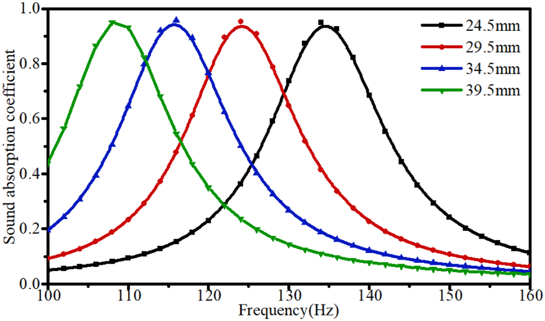
The convoluted channel greatly extends the propagation path of acoustic waves in the structure. Compared with linear propagation, the acoustic wave through the complex channel shows a slower equivalent speed of sound, a higher refractive index relative to the background medium, and higher energy loss. The energy loss mechanisms are mainly thermal and viscous. When a sound wave is incident to the inside of the convoluted channel, it will cause vibration of the air mass inside the channel such that the air and the inner wall of the channel undergo relative motion, and the acoustic energy will be converted into thermal energy under the effect of viscous damping, which will make the acoustic energy dissipate. At the same time, when the sound wave enters the channel, it will cause compression and expansion of the air mass at this point such that the temperature changes; thus, at the channel wall, heat exchange constantly occurs, resulting in a heat conduction effect, and the sound energy is converted into thermal energy and dissipated. Therefore, the thermal loss and viscous loss arise from the intense friction and relative motion between the air particles inside the convoluted channel and the inner wall of the channel, which makes the acoustic energy be dissipated in a large amount. For the structure in Figure 1, the single cell with a cavity length of 24.5 mm is selected for thermoviscous power consumption analysis, as shown in Figure 3(a)–(f), and its thermal power density, viscous power density, and total thermoviscous power density at the absorption peak frequency of 134 Hz are 0.12 W/m3, 19.8 W/m3, 19.8 W/m3, respectively. The thermal power consumption density, viscous power consumption density, and total thermoviscous power consumption density at the non-absorption-peak frequency of 100 Hz are 0.02 W/m3, 1.68 W/m3, and 1.69 W/m3, respectively. Figure 3 shows that the thermal power consumption of the structure is nearly negligible compared to the viscous power consumption, and the thermoviscous loss at the absorption peak frequency is much larger than that at the non-absorption-peak frequency. The rapid motion of the mass particles in the channel at the peak frequency makes the sound loss at the absorption peak frequency reach a maximum, for example, the sound absorption effect is maximized. Sound energy dissipation distribution of the single-cell structure at the absorption peak frequency (134 Hz): (a) Thermal power consumption density. (b) Viscous power consumption density. (c) Total thermoviscous power consumption density. Sound energy dissipation distribution at the non-absorption-peak frequency (100 Hz): (d) Thermal power consumption density. (e) Viscous power consumption density. (f) Total thermoviscous power consumption density.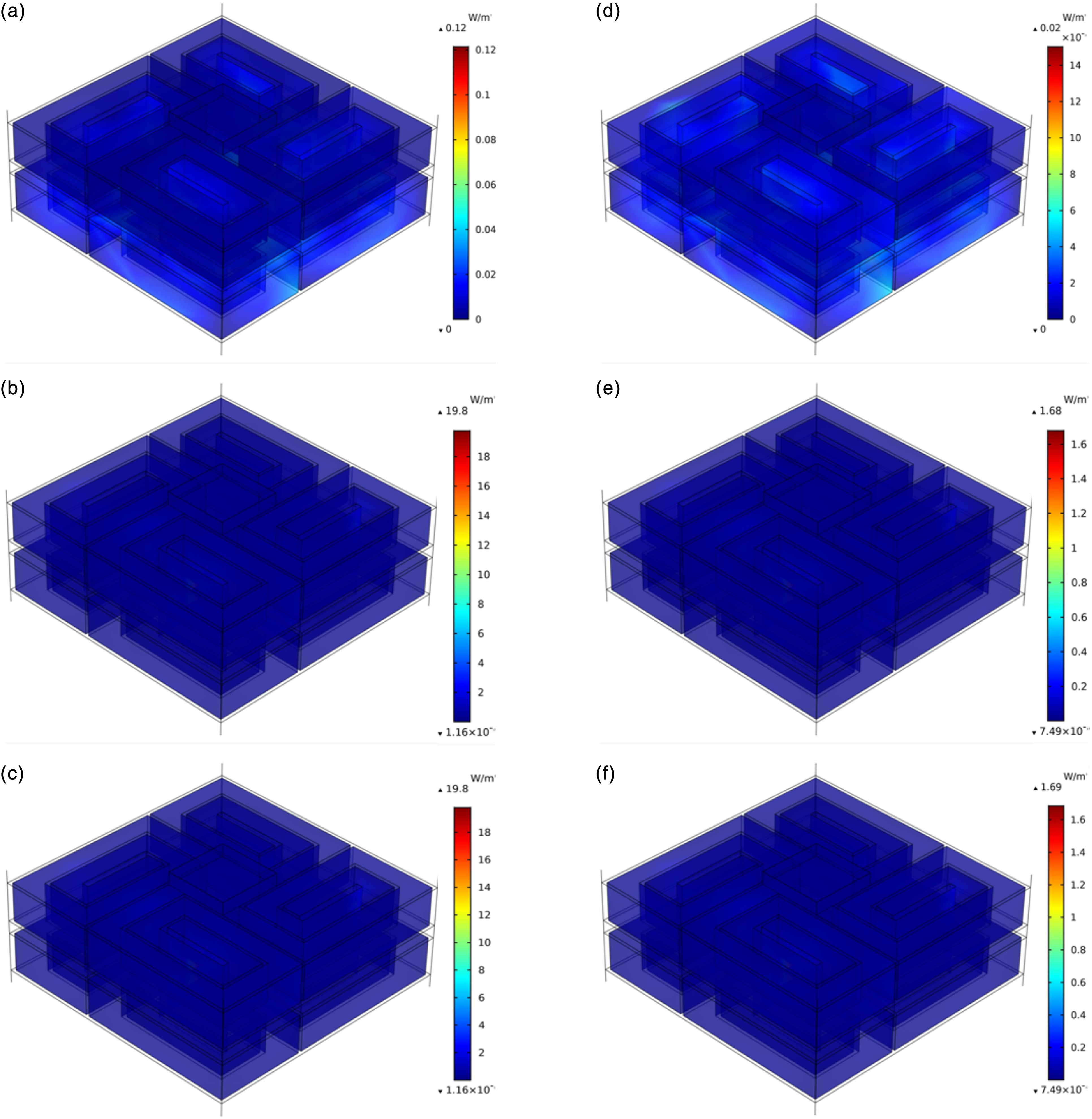
The air plasmonic particles inside the convoluted channel and Helmholtz cavity structure are analysed for their velocity, and their velocity distributions at the sound-absorbing peak and non-sound-absorbing-peak frequencies are obtained, as shown in Figure 4. As shown in Figure 4, the velocity of the plasmonic particles at the absorption peak frequency of the convoluted channel reaches 0.19 m/s, while the velocity of the plasmonic particles at the non-absorption-peak frequency is only 0.04 m/s; the velocity of the plasmonic particles in the Helmholtz cavity at the absorption peak frequency is 3.1×10⁻³ m/s, while the velocity of the plasmonic particles at the non-absorption-peak frequency is only 5.06×10⁻⁴ m/s. The velocity distribution of the air plasmonic particles at the absorption peak and non-absorption-peak frequencies of the Helmholtz cavity is analysed by velocity analysis, as shown in Figure 4. In the Helmholtz cavity, the velocity of the plasmonic particles at the absorption peak frequency is much larger than that at the non-absorption-peak frequency, so the friction loss of the air particles is the main reason for the generation of the absorption peak. (a) Velocity distribution of plasmonic particles in the convoluted channel at the absorption peak frequency (134 Hz). (b) Plasmonic particle velocity distribution in the convoluted channel at the non-absorption-peak frequency (100 Hz). (c) Plasmonic particle velocity distribution in the Helmholtz cavity at the absorption peak frequency (134 Hz). (d) Plasmonic particle velocity distribution in the Helmholtz cavity at the non-absorption-peak frequency (100 Hz).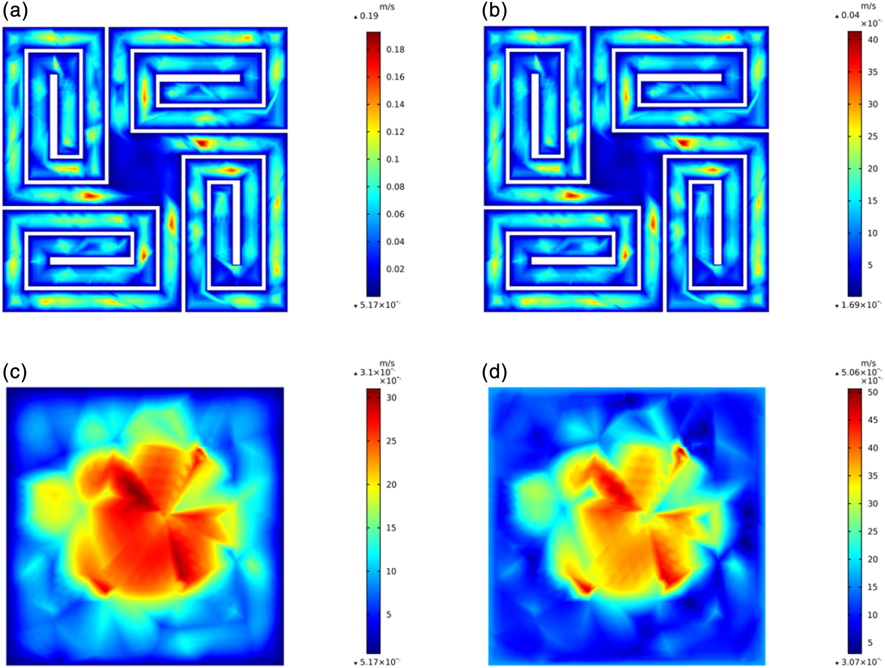
The incident acoustic wave can resonate with the air inside the Helmholtz cavity, and the energy generated by the air resonance is dissipated through thermal energy, thus realizing the sound absorption effect of converting acoustic energy into thermal energy. For the structure in Figure 1, the cavity sound pressure levels at the absorption peak and non-absorption-peak frequencies of the metamaterial structure are analysed, as shown in Figure 5. The sound pressure gradually increases through the convoluted channel to the cavity and reaches an extreme value in the interior of the cavity (in which the convoluted channel can be regarded as the length of the neck tube of the cavity). When the air inside the cavity resonates, the sound energy loss is maximized, and low-frequency absorption is achieved. The sound pressure level at the absorption peak frequency of 134 Hz reaches 116 dB, while the sound pressure level at the non-absorption-peak frequency of 100 Hz is only 104 dB, which is smaller than the sound pressure level at the absorption peak frequency. Sound pressure level distribution at the (a) 134 Hz absorption peak and (b) 100 Hz non-absorption-peak frequencies.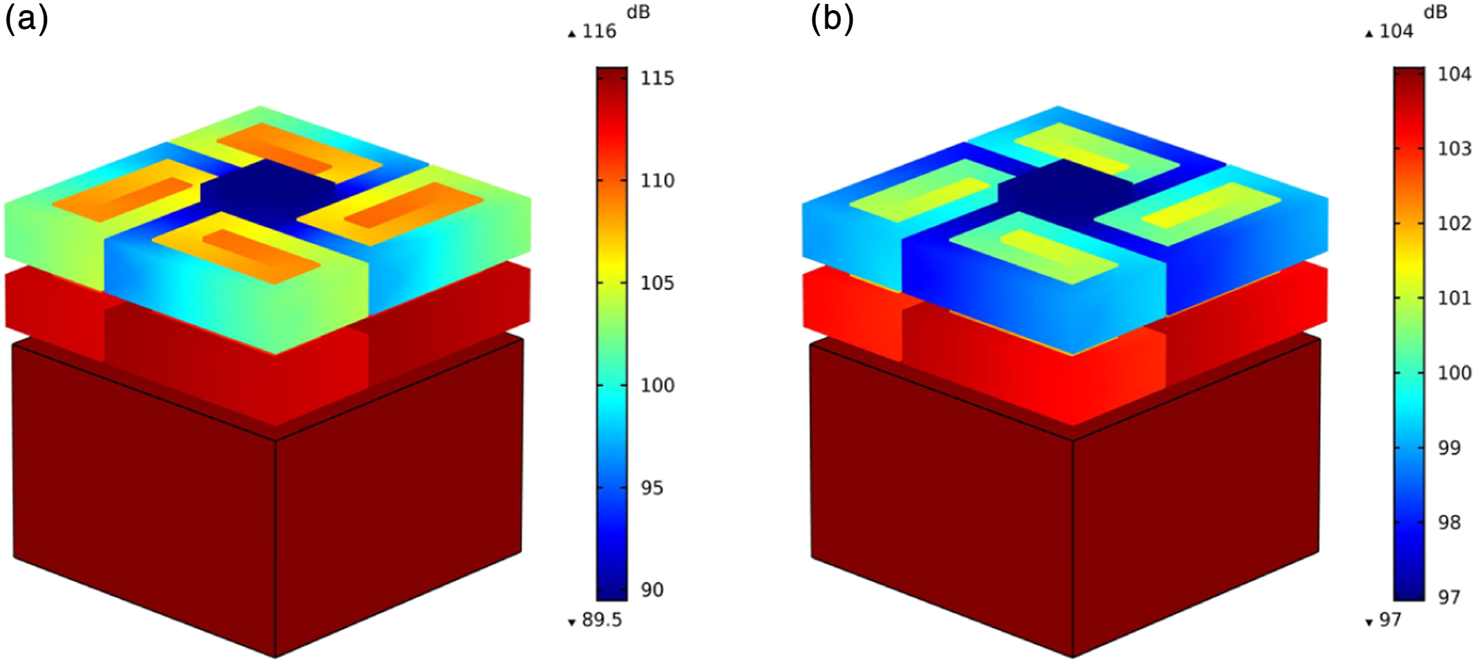
Series-parallel structure sound absorption characteristics analysis
Multicell coupling analysis
The conventional multicell coupled structure comprises a simple parallel arrangement of acoustic surfaces, which not only occupies too much acoustic surface area but also leads to a decrease in the broadband average absorption coefficient. In this paper, a metamaterial structure with a series-parallel arrangement is proposed, as shown in Figure 6(a)–(c). The area occupied by each gap structure is only 28% of that under direct parallel connection of single cells. By adjusting the Helmholtz cavity length of each cell, the three-cell parallel structure achieves a broadband sound absorption effect. As shown in Figure 6, the first cavity length of the series-parallel metamaterial structure designed in this paper is 29.5 mm, the second cavity length is 14.5 mm, the third cavity length is 7.5 mm, and the total length of the three-cell system is 114 mm; the three-cell parallel structure absorption curve is shown in Figure 6(d). The absorption coefficients of the series-parallel structure are all above 0.95 in the broadband range of 124–134 Hz. Compared with the direct parallel arrangement structure, the absorption surface of this coupled design is well controlled, and the linear decay effect of the absorption coefficients is avoided as much as possible such that the absorption curve is maintained at a high level in a broadband range. (a) Three-cell parallel structure, (b) top view of the structure, (c) structure splitting diagram, and (d) three-cell parallel structure sound absorption curve.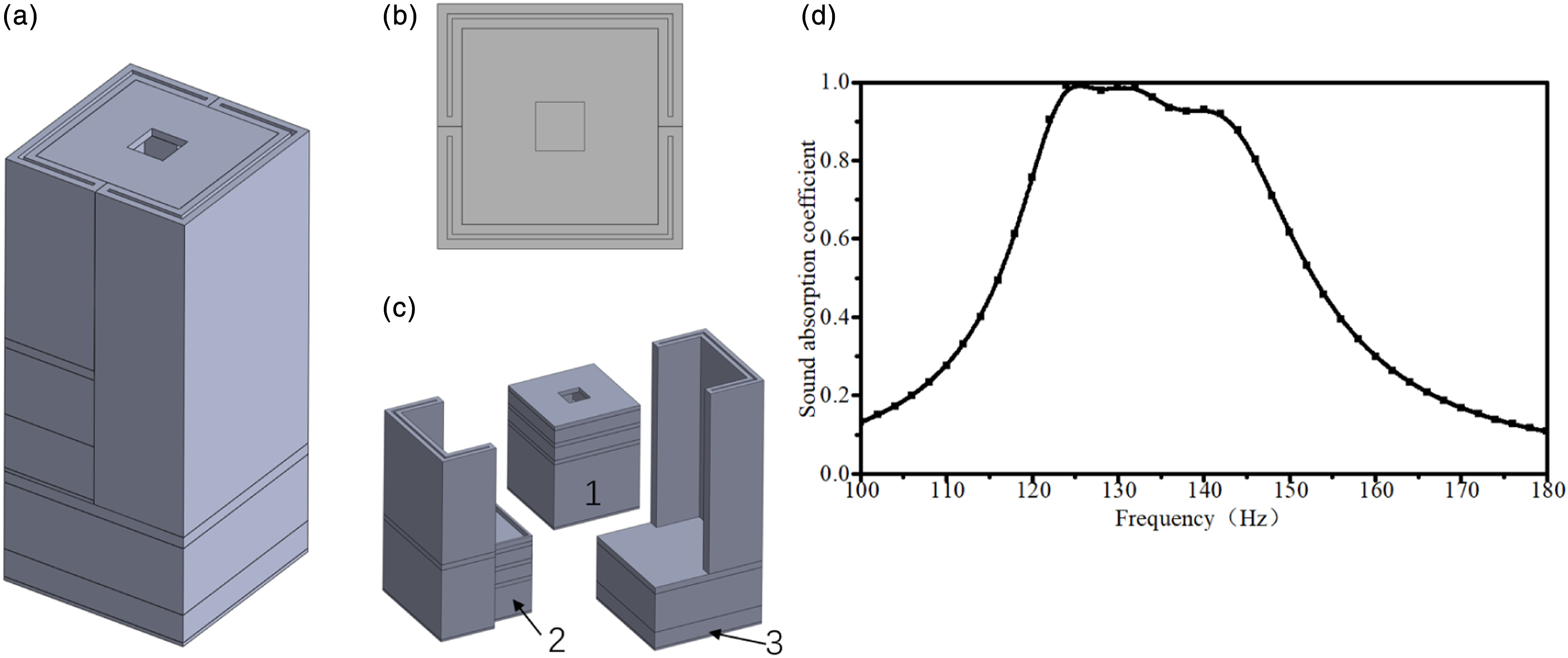
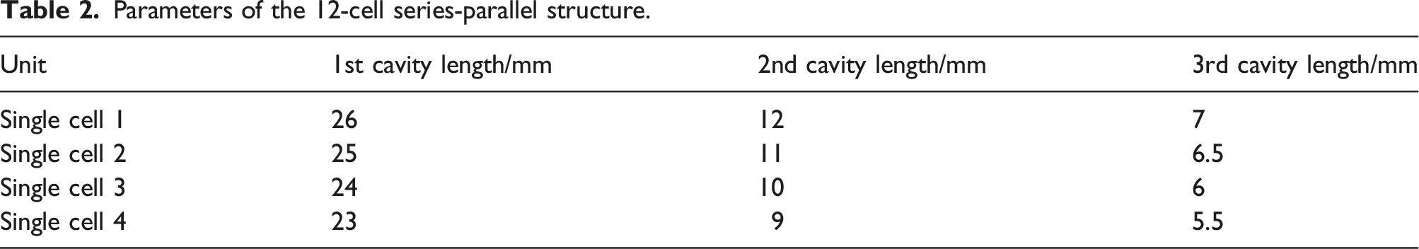
Based on the above three-cell parallel structure, four three-cell structures are arranged in parallel to design a 12-cell series-parallel coupling structure, as shown in Figure 7(a). By adjusting the length of the 12 cavities, the coupled structure achieves a low-frequency broadband sound absorption effect. The sound absorption curves of the four three-cell parallel structures are shown in Figure 7(b), and each three-cell parallel structure has different peak and valley frequencies; thus, the peak and valley frequencies of each structure are coupled in a coordinated manner so that the series-parallel coupled structure achieves a perfect sound absorption effect within a certain broadband range. The Helmholtz cavity lengths of each single-cell structure are shown in Table 1. The sound absorption effect of the coupled structure in the low-frequency range is calculated, and the absorption curve is shown in Figure 7(c). Its average absorption coefficient in the broadband range of 124–146 Hz reaches 0.96, which signifies nearly complete sound absorption. (a) Twelve-cell series-parallel structure, (b) acoustic absorption curves for each single cell, and (c) series-parallel structure sound absorption curve. Parameters of the 12-cell series-parallel structure.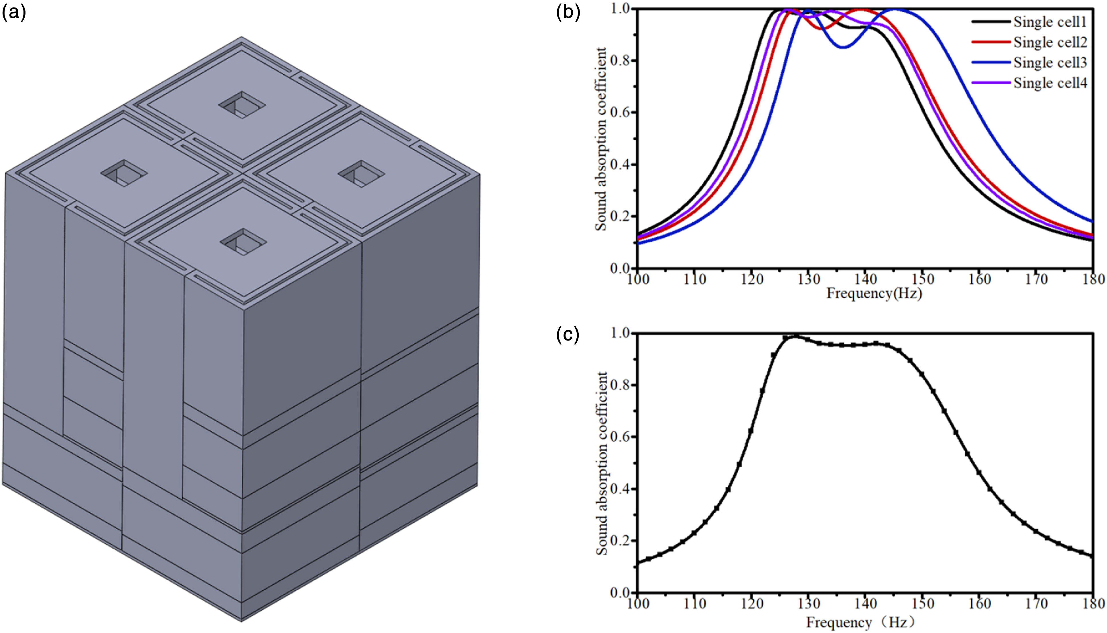
Model experiments
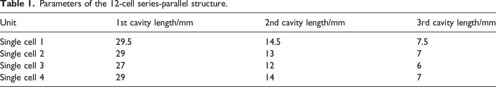
To verify the acoustic absorption performance of the metamaterial designed in this paper, a 12-cell series-parallel coupled structure was prepared using 3D printing, and the acoustic absorption performance was tested using the standing wave method with a square impedance tube, as shown in Figure 8(a), (b). The instrument used for the experiments was an Acoustiguide F100 impedance tube system, which included a VA-Lab software module, a four-channel digital acquisition unit, a square impedance tube, a power amplifier, and a microphone. The impedance tube had an inner diameter of 102 mm and a theoretical test frequency range of 50–1600 Hz. The experimental model was placed on one side of the impedance tube, and the dual microphone transfer function method was used to conduct the sound absorption performance experiments. (a) Experimental system, (b) experimental prototypes prepared by 3D printing, and (c) comparison of sound absorption curves between numerical simulation and model experiments.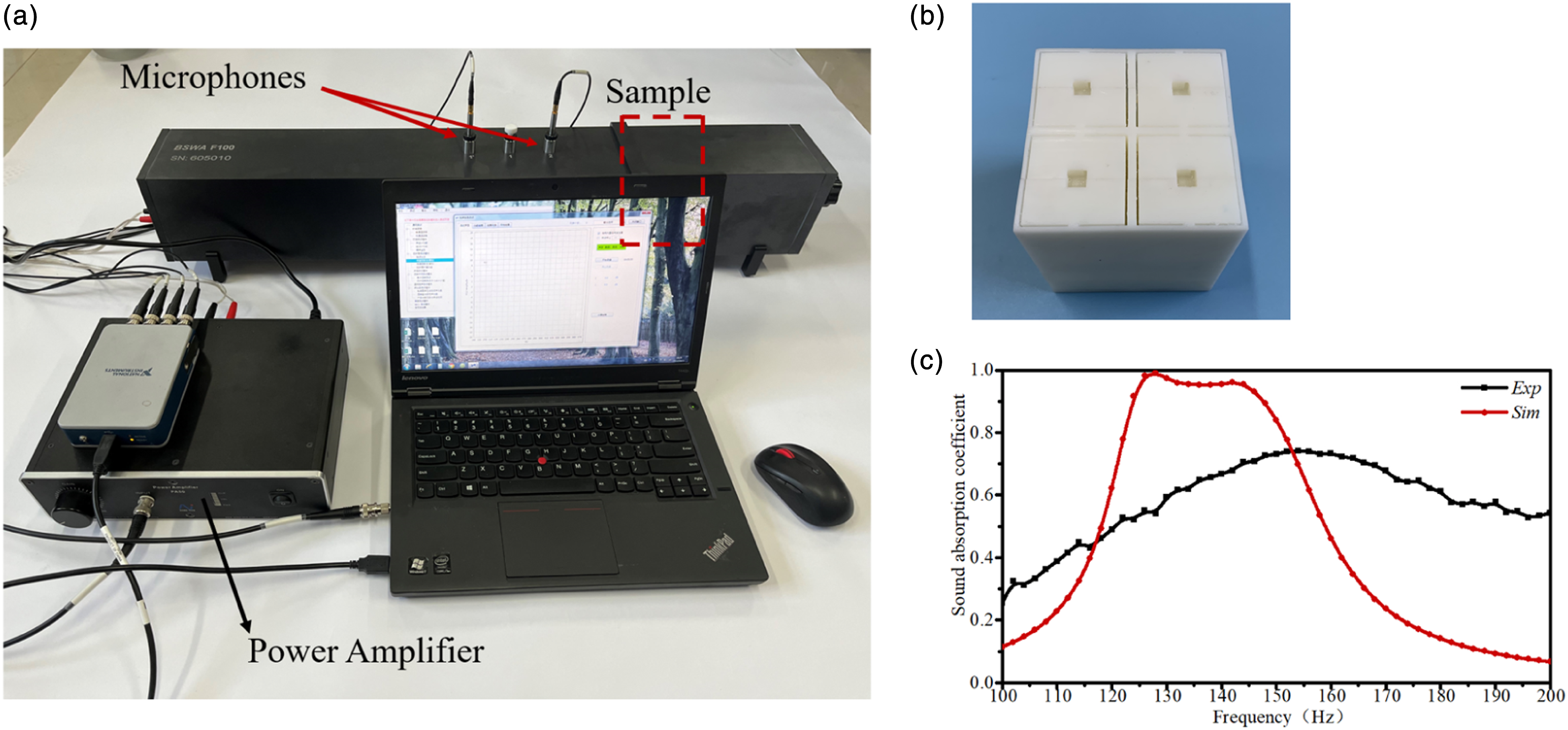
A comparison of the absorption curves from the model experiments and the numerical simulation is shown in Figure 8(c). As seen from the figure, the peak broadband frequencies of the experimental results deviate from the numerical simulation results, and the broadband sound absorption effect is lower than that in the simulation results. These phenomena are attributed to the following: (1) The minimum size of the inner wall thickness of the convoluted channel of the model designed in this paper is 0.5 mm, and the local structure of the model exhibits large deformation, as seen from the experimental model. (2) The experimental model was prepared by bonding the structures of small parts, and leakage and overflow of glue occurred during model preparation. (3) The size of the prepared model structure is 100 mm × 100 mm, and the size of the impedance tube is 102 mm × 102 mm. Even with the gap between the experimental model and the impedance tube plugged by PTFE tape and petroleum jelly, significant sound leakage inevitably occurs.
Single-cell structure design optimization and experiment
The single-cell model proposed above was optimized and designed to address the problems arising from the model experiments in Figure 8(c). The optimized single-cell structure is shown in Figure 9, in which the perforated edge length d for the perforated plates in layers 1 and 5 is changed from 10 mm to 8 mm, the perforated edge length e for the perforated plate in layer 3 is changed from 3 mm to 2 mm, and the inner wall thickness h of the convoluted channel is changed from 0.5 mm to 1 mm. The perforated plate thickness a is changed from 2 mm to 1 mm, and the convoluted channel thickness b is reduced from 6 mm to 5 mm, while part of the solid structure is changed to a hollow structure to further optimize the total length of the structure and reduce the weight and preparation cost of the model. To avoid excessive clogging of the seams during the preparation process, the width of the seams was increased from 1 mm to 1.5 mm. Schematic diagram of the structure of the new tandem single cell with a convoluted channel and a Helmholtz cavity. (a) Tandem single-cell structure. (b) Tandem single-cell split structure. (c) Layers 1 and 5 perforated plates. (d) Convoluted channel. (e) Layer 3 perforated plate.
Parameters of the 12-cell series-parallel structure.
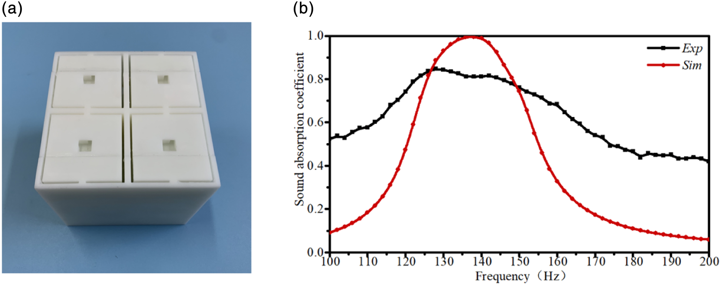
(a) Experimental prototypes prepared by 3D printing; (b) comparison of the sound absorption curves between numerical simulation and model experiments.
The experimental setup in Figure 8(a) was used to perform sound absorption performance experiments on the optimized structure, and a comparison of the absorption curves from the model experiments and numerical simulation is shown in Figure 10(b). In the numerical simulation results, the multicell structure shows an average absorption coefficient of 0.97 in the range of 130–145 Hz, signifying nearly complete sound absorption. Figure 10(b) shows that the experimental results remain lower than the broadband peak in the numerical simulation due to errors during model preparation, but the experimental results are in good agreement with the numerical simulation results in terms of the absorption bandwidth, and the absorption broadband frequency range and peak frequency overlap with the simulation results.
Conclusion
In this paper, a series-parallel arrangement of low-frequency metamaterials is designed to address the difficult problem of low-frequency noise control. The structure mainly comprises convoluted channels and Helmholtz cavities in series, with the conventional parallel arrangement of multiple cells replaced by a sandwich arrangement, which somewhat reduces the influence of absorption broadband attenuation introduced by the direct parallel arrangement. The sound absorption mechanisms and characteristics of the single-cell and multicell structures are investigated with full consideration of the thermal loss, viscous loss, and resonance absorption of Helmholtz cavities. The average absorption coefficient of the metamaterial structure before optimization reaches 0.96 in the broadband range of 124–146 Hz, signifying nearly complete sound absorption. However, due to fabrication errors during model preparation, the peak broadband frequency in the experimental results deviates from that in the numerical simulation results, and the experimental broadband sound absorption is lower than the simulated absorption. By analysing the error sources, dimensional optimization of the metamaterial structure is carried out to yield an average absorption coefficient of 0.97 in the range of 130–145 Hz. These final experimental results are in good agreement with the numerical simulation, verifying the sound absorption effect.
Footnotes
Declaration of conflicting interests
The author(s) declared no potential conflicts of interest with respect to the research, authorship, and/or publication of this article.
Funding
The author(s) received no financial support for the research, authorship, and/or publication of this article.