
Abstract
In this study, a multifunctional acoustic metastructure is proposed to achieve both effective low-frequency sound isolation and acoustic energy harvesting. A metallic substrate with proof mass is adopted to generate the local resonant phenomenon for the purpose of overcoming the drawbacks of the previous rubber film-based acoustic metastructure; the latter usually requires an elaborate tension process. Numerical simulations show that the proposed structure exhibits excellent noise isolation performance in the low-frequency band. Meanwhile, the incident sound energy can be converted into electrical energy with the help of an added piezoelectric patch. Numerical simulation results indicate that the harvested energy can reach the mW level. The parameters’ influence on the metastructure’s vibro-acoustic and energy harvesting performance are discussed in detail. An optimized configuration is selected and used for experimental study. It is demonstrated that 0.21 mW electrical power at 155 Hz can be harvested by the proposed metastructure under 114 dB sound pressure excitation.
Introduction
Low-frequency noise isolation or attenuation has always been a focus of scientific research and industrial engineering. Very significant amounts of this band of noise are emitted by industrial plants, transportation vehicles, and civic buildings. Typical noise sources include pumps, electric motors, electric transformers, cooling towers, and traffic vehicles. In the low-frequency range, the wavelength of sound waves can be meters long, which transmits through thin-walled structures easily without remarkable attenuation. 1 Accordingly, it is important to investigate effective low-frequency noise control methods.
Previous studies have demonstrated that an active noise control, 2 or active structural acoustic control approach, 3 can suppress the low-frequency noise effectively. However, the active control system cost is high and suffers from system stability problems.
The acoustic metamaterials or subwavelength acoustic metasurfaces open a new way to manipulate acoustic waves, which can be used for wave-steering, 4 realizing generalized Snell’s law 5 and low-frequency noise insulation. 6 As reported in the low-frequency noise insulation application, it was found that the designed metastructures are usually composed of elastic rubber films fixed to rigid edges, and a tension process is necessary before a small weight of mass is added to the films. 7 The local resonance mechanism makes the metastructure cell behave like an independent oscillator, and multiple locally resonant metamaterial cells can be further assembled as a panel for enhanced sound isolation and large-scale applications. 8 However, from the engineering point of view, the ductile nature of the rubber film causes durability issues during deployment. In addition, the tension process increases the fabrication cost, and the tension variation introduces great uncertainties into the fabricated unit’s natural frequencies. 9
The incident sound energy can be harvested rather than dissipated, which makes the investigation of the acoustic metastructure’s energy harvesting ability a very interesting issue. The converted electrical energy can be further stored and utilized by low-power electronic devices, which have broad application prospects for the Internet of Things. It should be noted that although acoustic energy harvesting (AEH) can be efficiently realized within the thermo-acoustic tube, 10 such mechanism is not included in this study, and the excitation source is assumed as pure acoustic.
Following previous relevant acoustic energy harvesting studies, we find that acoustic resonators are usually introduced to amplify the incident sound pressure, such as the Helmholtz resonator 11 or quarter-wavelength resonator, 12 showing bulky for low-frequency applications. Metamaterial inspired energy harvesting studies have been initialized in recent studies, but the reported frequencies are located in the mid to high range.13,14 Only few research works in the low-frequency range are reported in recent years, adopting the piezoelectric mechanism 15 or electromagnetic mechanism, 16 the structural parameter influences on the system’s vibro-acoustic properties and energy harvesting performance are not fully reported. Recently, a coiled-up metamaterial cavity is proposed to introduce sound pressure amplification, and stepped proof mass is introduced to improve the piezoelectric plate’s energy harvesting performance within the cavity. 17
In summary, little research work has been carried out with respect to metastructure-based low-frequency acoustic energy harvesting. The influence of the structural parameters on energy harvesting and vibro-acoustic properties has not been well reported.
In this paper, a durable acoustic metastructure is proposed, which can achieve both effectively low-frequency noise isolation and energy harvesting capabilities. Compared with the rubber film-based acoustic metastructure, the substrate is replaced by metallic material, and its durability is greatly improved. A piezoelectric patch and a proof mass are added to the substrate, and the finite element method is used to investigate the local resonant structural properties.
A sample acoustic metastructure model is described in the next section for the computational model setup. Then the sample’s general vibro-acoustic properties are briefly depicted. The parameters’ influences, such as the excitation sound pressure, the shape of the proof mass and substrate thickness and material’s influence on the sample, are investigated next. A favorable configuration is selected for experimental verification. The experimental system was set up, and the relevant measured results are given in the Experimental demonstration section.
Acoustic metastructure sample model description
From previous studies, it is known that a rubber film-based substrate requires tension to give the film sufficient stiffness, and the dynamic characteristic of the membrane film is very sensitive to the tension value. This shortcoming can be overcome via increasing the substrate’s Young’s modulus. Here, a metallic substrate is used, and the tension process can be eliminated.
As shown in Figure 1, the proposed metamaterial structure is composed of three parts. The base part is a circular membrane. The middle part is a circular piezoelectric PZT-5H patch and the top part is a cylinder proof mass.
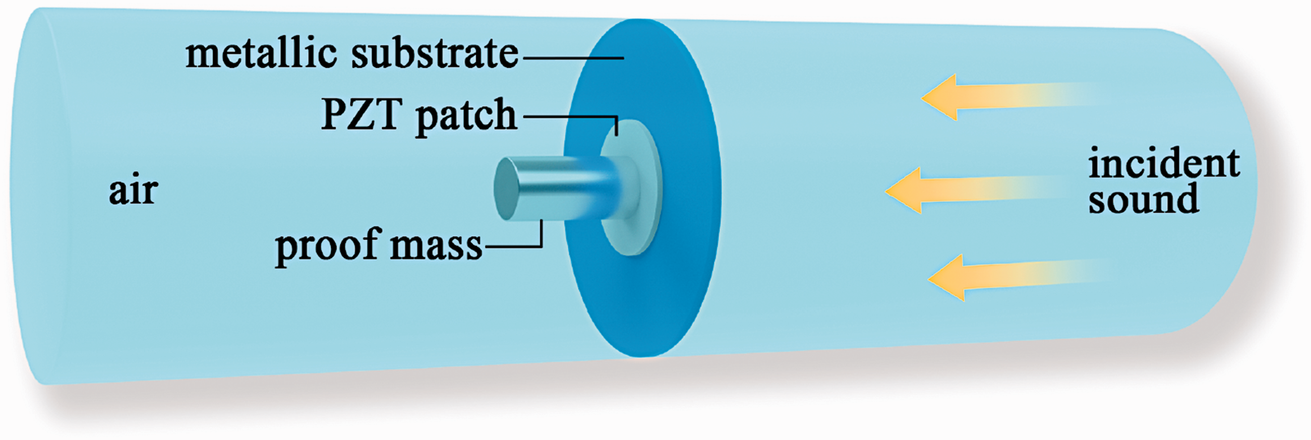
Schematic diagram of the proposed metamaterial structure.
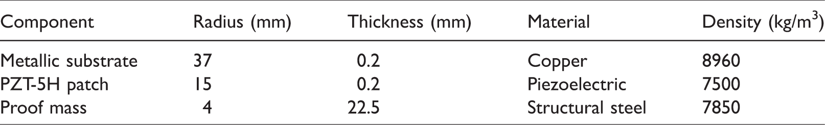
The three components are bonded centrally and the corresponding parameters are given in Table 1. According to these structural parameters, the calculated total weight of the sample is 17.6 g. The air speed is set to 343 m/s, and the air density is set to 1.29 kg/m3. The structural loss factor is defined as 0.04.
Component parameters of the metastructure.
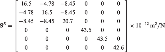
The PZT-5H’s compliance matrix at constant electric field is
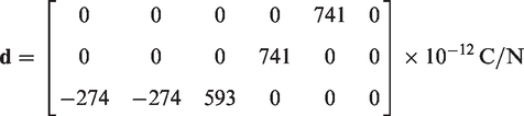
The PZT-5H’s direct piezoelectric coupling matrix is
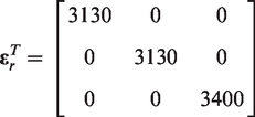
The PZT-5H’s relative permittivity matrix under constant stress is
Here, the COMSOL™ finite element software is adopted, and the numerical model is solved via frequency analysis. A clamped boundary condition is set at the edges of the circular substrate and is placed inside an acoustic tube, with a total length of 200 mm. The excitation source is plane acoustic wave, and radiation acoustic boundaries are used at the tube’s two terminals, which makes the transmitted sound wave propagate in the downstream without reflection. Other acoustic boundaries are assumed as rigid walls.
For the mechanical domains (substrate, piezoelectric patch, and proof mass), the finite element meshes are generated using the swept method. With respect to the acoustic domain, meshes are generated using the free tetrahedral method. The minimum structural element size is 0.04 mm and the maximum structural element size is 4 mm. The minimum acoustical element size is 0.04 mm and the maximum acoustical element size is 4 mm. The total number of elements is around 42,407.
The acoustic–structure interface is added into the model to solve this fluid–structural interaction problem. The electrostatics and electrical circuit interfaces are also added into the model, which are used to simulate the piezoelectric effect and the current flowing to peripheral electrical circuit. The calculated electrical power value is essential for the energy harvesting performance evaluation and optimization.
The finite element analysis is performed in the frequency range of 20 Hz–1500 Hz. The incident sound pressure is 10 Pa, which means the sound pressure level (SPL) equals 114 dB. The piezoelectric patch is connected by a 10 kΩ resistor, which is found to provide the optimum resistance as discussed in the Parameter influences on acoustic energy harvesting section.
Vibro-acoustic characteristics of the metastructure sample
Vibro-acoustic properties at the resonant and anti-resonant frequencies
For the local resonant acoustic metamaterial unit, previous studies have shown that the sound transmission dip occurs around the first resonant frequency and is mainly governed by structural damping. The sound transmission peak occurs near unit’s first anti-resonance frequency.6,7
For the numerical model in this study, the calculated first resonant frequency occurs at 151 Hz and the first anti-resonance frequency occurs at 450 Hz. Correspondingly, the sample’s sound pressure distribution, air velocity, and structural displacement are presented in Figure 2.
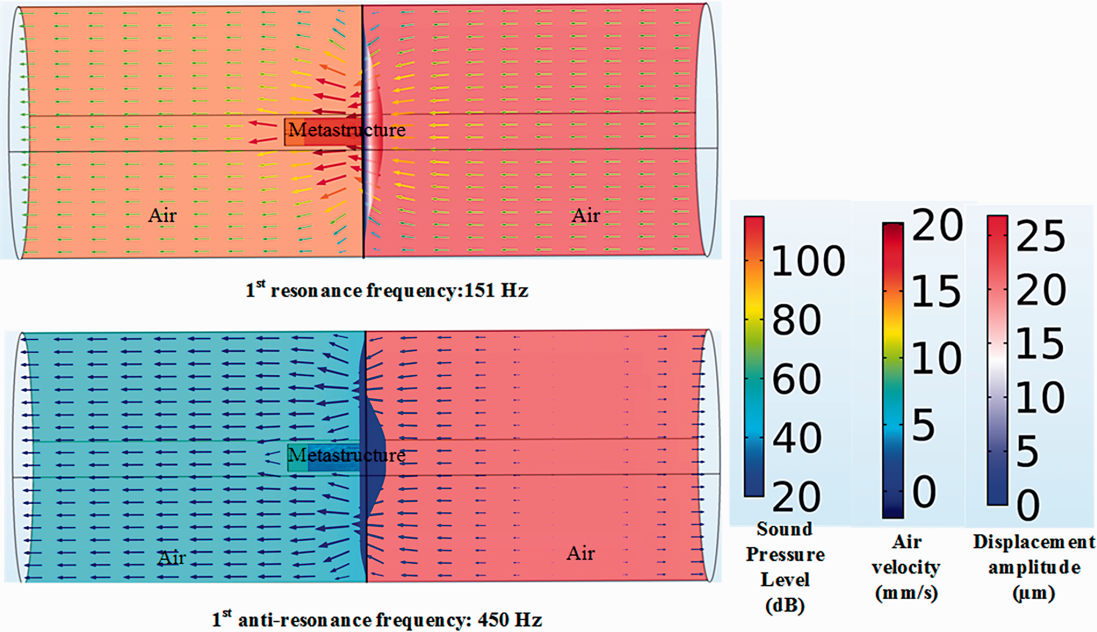
Vibro-acoustic properties of the sample at interesting frequencies.
The background color inside the tube (air domain) represents the SPL distribution; the color of arrows represents the magnitude of air velocity. The proposed metastructure is located in the figure’s middle part, and its movement is represented using displacement amplitude.
It is shown at the first resonant frequency, the maximum structural displacement can be up to 25 µm. The air velocity value represented by the arrow reaches 20 mm/s. In contrast, at the first anti-resonant frequency, the maximum displacement reduces sharply and is only 0.48 µm. The small amount of structural displacement makes the metastructure behave very rigidly, which is suitable for sound insulation. Meanwhile, the transmitted sound velocity is also reduced sharply to only 0.06 mm/s, indicating that the transmitted sound energy is very small.
Effective dynamic mass density characteristics
To gain further insight into the sound transmission property, we examine the structure’s effective dynamic mass density, which is defined as
6

The calculated effective dynamic mass density is given in Figure 3.
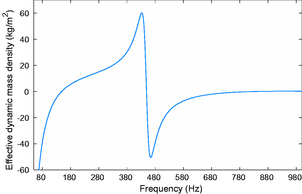
Effective dynamic mass density of the sample.
As shown in Figure 3, the
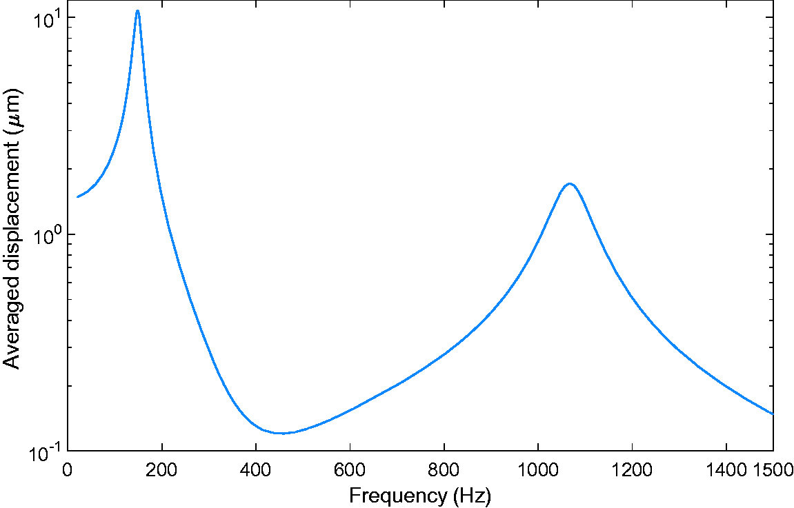
Average displacement of the substrate in vertical direction.
Parameter influences on acoustic energy harvesting
Optimal resistance determination
To obtain the maximum amount of harvested power, the external circuit resistance value should be tuned to match the generator’s source impedance. The output voltage and the corresponding calculated power with load resistance variation at the structural resonance frequency are shown in Figure 5.
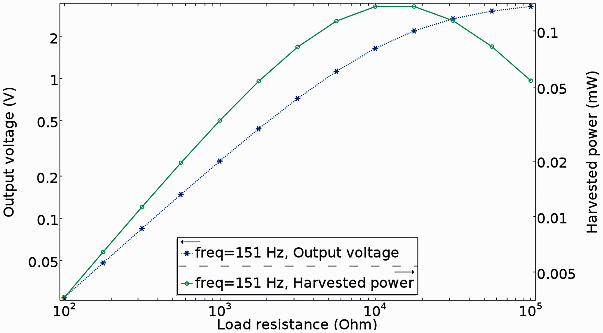
Output voltage and harvested power under different load values.
The identified optimum resistance is 10 kΩ, and the harvest power is achieved at the maximum value under this condition.
The influence of incident sound pressure
Figure 6 shows harvested electrical power value versus the incident sound pressure and the corresponding curve fitting result.
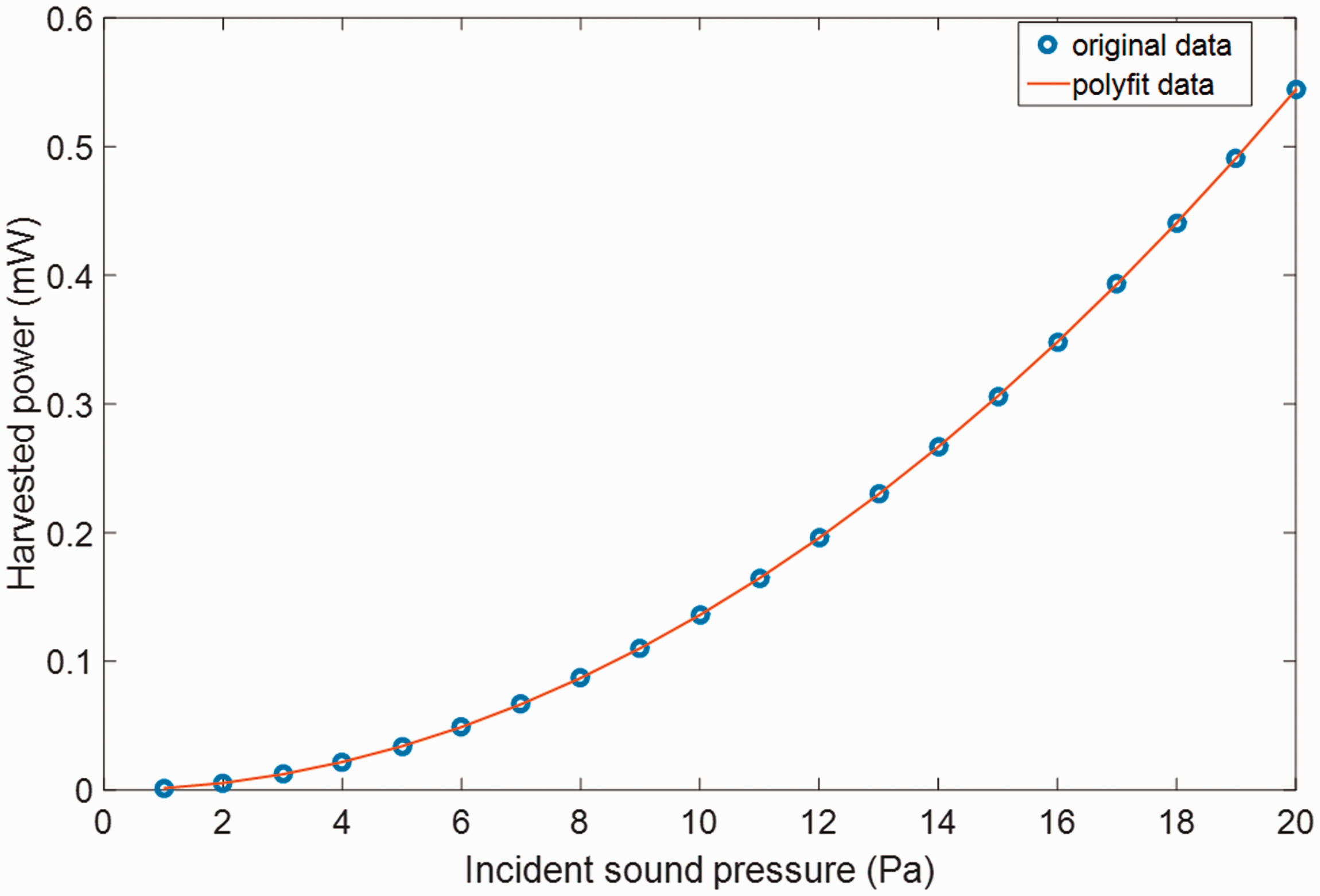
Harvested power as a function of incident sound pressure.
It is shown that the harvested power increases quadratically with the incident sound pressure, which has been disclosed in an analytical study. 18
In this study, the polynomial curve fitting equation is

The quadratic relation obeys the physical law, which can be deduced as follows.
Assuming the incident sound pressure is 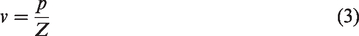
The sound intensity 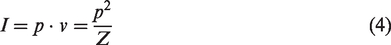
Accordingly, the incident sound power 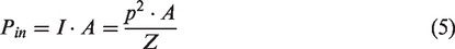
If the incident power is too large, causing the system to exhibit strong non-linear dynamic properties, the above relation should be reconsidered.
The influence of the shape of the proof mass
The added parameters of the proof mass shape at the metastructure’s center can also influence the energy harvesting performances. Here, the proof mass samples are assumed to have a cylinder shape with the same mass value.
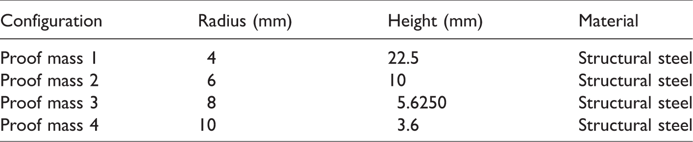
Four geometric configurations are considered, and the variation is achieved by changing the cylinder’s radius and height parameters. The detailed geometrical values are given in Table 2. In this simulation, the proof mass’ volume size is set at 360 mm3, and the mass weight is 8.87 g.
Proof mass geometrical parameters.
As shown in Figure 7, the simulation result shows that for a given proof mass weight, the mass’ geometric parameters can influence the harvested power significantly. At the first resonance frequency, the largest power value is 0.14 mW (smallest radius cylinder), and the smallest power value is 0.09 mW (largest radius cylinder). The discrepancy is as much as 56%.
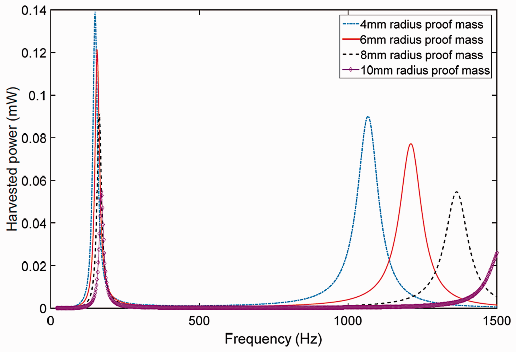
Effect of the proof mass shape on harvested power.
This reason for this is that when the piezoelectric patch is bonded with proof mass, the bonding surface covered by the proof mass will not generate strain under sound wave excitation, and consequently no electrical charge is generated. Therefore, a larger radius proof mass has adverse effect on the energy harvesting power value.
However, the mass’ radius cannot be infinitely small. One important reason is that for the same weight, a smaller radius will bring about a larger height, making the overall system less compact; another reason is that when the radius is small enough, the concentrated stress can exceed the piezo patch’s bearing limit, causing material fracture and failure.
The influence of substrate materials
To investigate the substrate influence on energy harvesting performance, three different materials are considered: aluminum, copper, and high-strength alloy steel. These material properties are given in Table 3.
Substrate material properties.

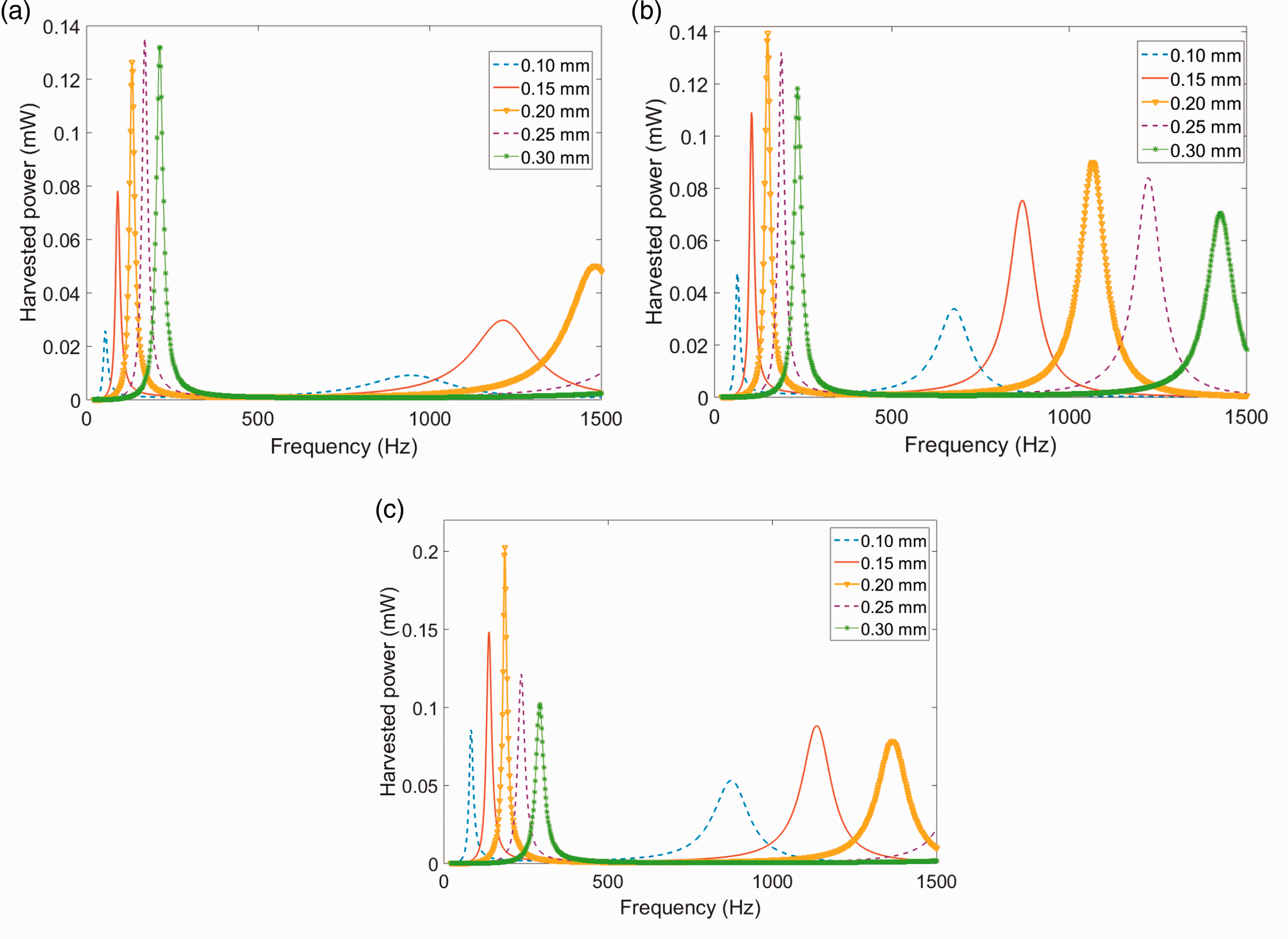
The structural loss factor
The substrate thickness is kept to be 0.2 mm with different materials and the obtained harvested power is shown in Figure 8.
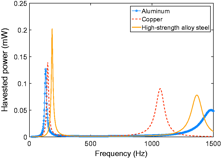
Harvested power with different substrate materials.
For small structural loss value around the resonance frequency, the damping ratio
Harvested power for different damping ratios.
The influence of substrate thickness
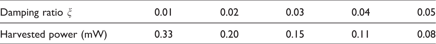
Figure 9 shows the influence of substrate thickness on the harvested power.
Variation of harvested power with different substrate thicknesses: (a) aluminum substrate, (b) copper substrate, and (c) high-strength alloy steel substrate.
The simulation result indicates that to generate maximum power, there exists an optimal thickness ratio between the piezo patch and the substrate material. Here, the piezo patch’s thickness is kept to be 0.2 mm and the substrate thickness is varied from 0.1 mm to 0.3 mm with 0.05 mm step.
The resonance frequency can be changed during the thickness variation. For plate type structure, the flexural rigidity 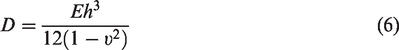
Meanwhile, impedance matching is optimized for the first mode, and the load resistance is determined according to the following equation
21
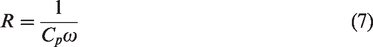
The calculated load resistance values for different simulation cases are shown in Table 5.
Load resistance values in the simulation.
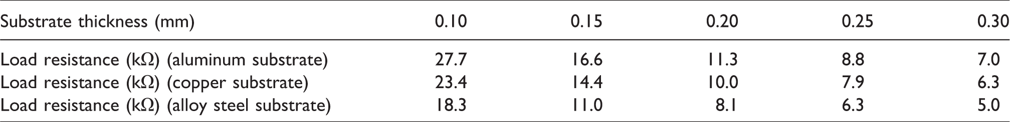
At the first resonance frequency, the optimal thicknesses for the aluminum, copper, and high-strength alloy steel substrates are 0.25 mm, 0.2 mm, and 0.2 mm, respectively. Among the optimum values, the 0.2-mm thick high-strength alloy steel substrate generates the largest output power (0.2 mW), which is 46.8% higher than the aluminum substrate optimal case and 42.8% higher than the copper substrate optimal case. The energy conversion efficiency can reach 20% for the 0.2-mm thick high-strength alloy steel substrate case.
The effective electromechanical coupling factor determines the effectiveness of piezoelectric energy harvester. As shown in previous studies, the effective electromechanical coupling factor is influenced by the thickness ratio and Young’s modulus ratio of piezoelectric patch and substrate.22,23
When the substrate thickness value is too small, the neural axis of the composite structure will move into the piezoelectric layer, which introduces electrical charge cancellation and generates little electrical power and very low effective electromechanical coupling factor.
When the substrate thickness is increased, the neutral axis will be located in the substrate layer gradually, indicating the charge cancellation is alleviated, and larger electrical power is obtained.
Correspondingly, as shown in Figure 9, for different substrate cases, the harvested power is increased before it achieves a maximum value. Meanwhile, for different substrate material with the same thickness, it has been shown that the substrate with larger Young’s modulus generates a larger electrical power. This is attributable to the fact that the neutral axis is farther away from the piezoelectric layer, resulting in less charge cancellation and higher electromechanical coupling factor.
When the substrate thickness is further increased, the vibration response of the structure plays a more important role – the generated electrical power is related not only to the distance of the neural axis but also to the deflection of the structure. Therefore, when the substrate thickness increases to a certain extent, this latter factor plays a more important role. During the process, there exists an optimal thickness for the substrate, which corresponds to the maximum power.
As shown in Figure 9, the generated electrical power drops when the substrate thickness is further increased over the optimal thickness. Here, the steel substrate case drops more quickly owing to the larger stiffness causing the deflection to decrease more quickly, which corresponds to a sharper electrical power drop off.
Experimental demonstration
According to the previous simulation analysis given in the Parameter influences on acoustic energy harvesting section, the 0.2-mm thick high-strength alloy steel, 4-mm radius proof mass, and 0.2-mm thick PZT-5H configuration provides the maximum harvested power value. Therefore, this configuration is chosen for the following experimental study. The fabricated components are weighted on a precise scale and the measured total weight is 17.02 g, which has a gram bias of only 0.58 compared to the theorical prediction.
Figure 10(a) shows the photograph of experimental system for the metastructure’s performance evaluation. The corresponding schematic diagram is given in Figure 10(b).
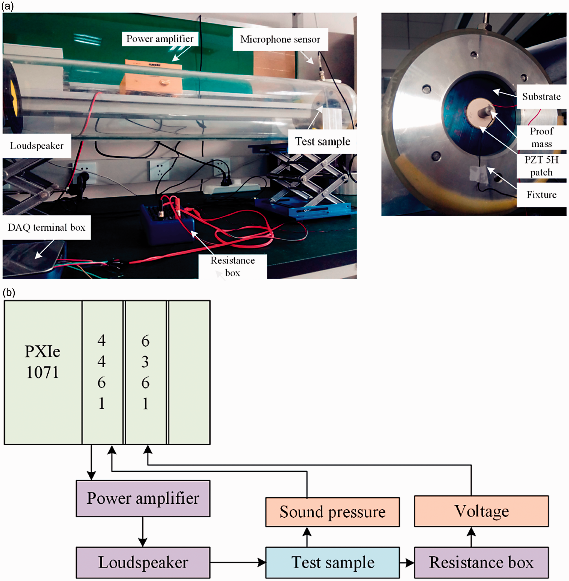
Experimental system setup. (a) Photograph of the experimental system. (b) Schematic diagram of the experimental system.
In the experimental system, an NI PXI-4461 AO channel (24 bits) provides a programmable signal to an audio power amplifier, which then drives a 5.5-inch loudspeaker (HiVi F5). An acrylic tube (length 1 m, thickness 8 mm, inner radius 77 mm) is used for plane sound wave propagation. To generate plane sound waves, the excitation frequency should be below the tube’s cutoff frequency, which is about 1300 Hz. A fixture unit was designed and fabricated, which helps to affix the metastructure to acrylic tube. Pattex™ super glue was used to bond the proof mass to the center of the PZT-5H patch. The PZT-5H patch was further bonded to the center of the disk’s center.
The incident sound pressure was measured using a G.R.A.S 40 PP microphone sensor (sensitivity 51 mv/Pa), and it was sampled by the NI PXI-4461 AI channel (24 bits). The SPL was calculated with the help of LabVIEW™ sound and vibration measurement suite. The harvester’s output voltage was measured by the NI PXI-6361 AI channel (16 bits).
A band limited white noise (20 Hz–1000 Hz) is used as the excitation signal, which is generated by the NI-DAQ system and is amplified by the audio power amplifier to drive the loudspeaker. A microphone sensor (at the tube’s end) is used to measure the excitation sound pressure and the acquired signal is analyzed via LabVIEW sound and vibration measurement suite. The measured result is shown in Figure 11(a).
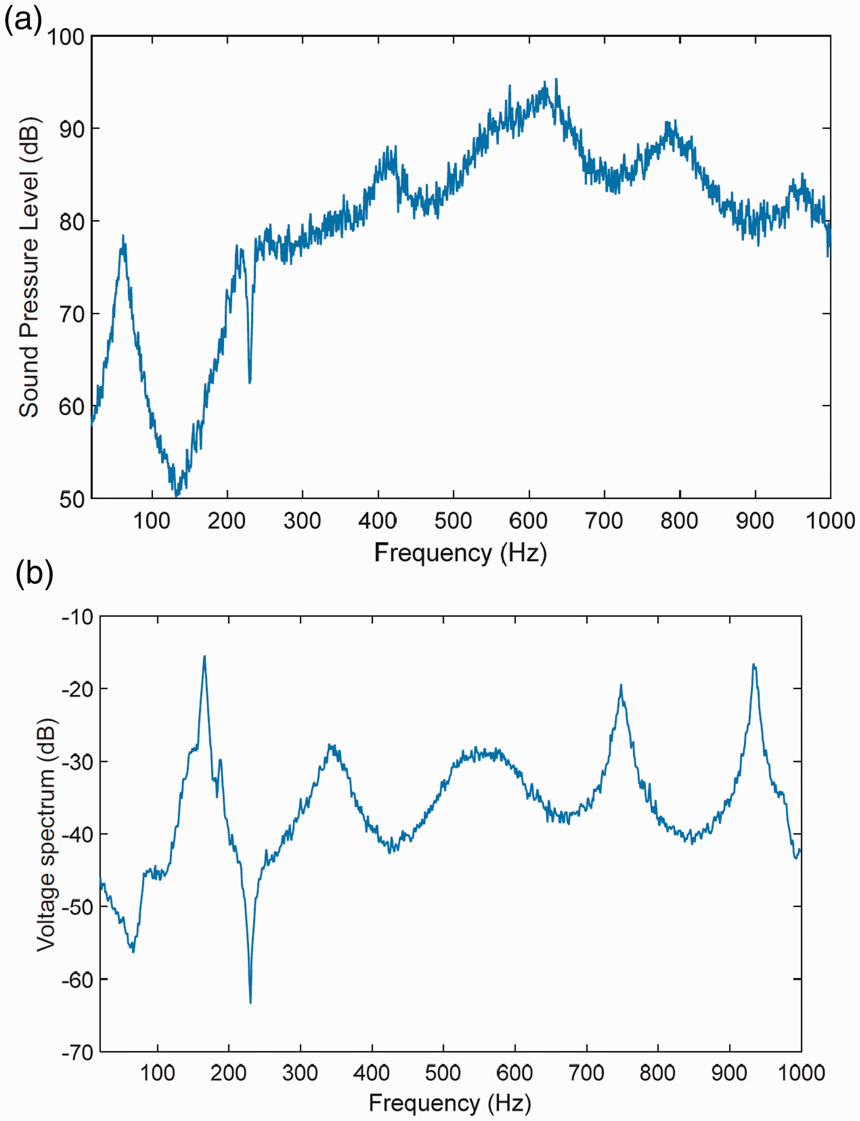
Incident sound spectrum and corresponding generated voltage spectrum. (a) Incident sound wave frequency properties. (b) Generated voltage spectrum from the piezoelectric path.
According to Figure 11(a), the sound spectrum is not uniform. This can be caused by many factors, such as speaker’s dynamic properties, ambient surrounding supports.
Secondly, the fabricated sample’s frequency property is measured. The test structure is mounted at the tube’s end, and the band-limited stochastic acoustic sound wave is used as the excitation source. Due to the piezoelectric effect, the piezoelectric patch’s voltage can be acquired to reveal the structure’s frequency property.
The measured frequency response is shown in Figure 11(b). It is shown that in the band of 100–200 Hz, although the acoustic excitation is weak, due to the metastructure’s local resonance property, a large voltage peak can be found. At the higher frequency band (200 Hz–1000 Hz), the incident energy is much larger than the previous low-frequency band, which causes the structure to be strongly excited than the low-frequency band. Besides, there are also some voltage peaks at high frequencies, and these peaks have close relation with the incident sound spectrum.
The measured first resonance frequency occurs at 155 Hz, whereas the simulated result corresponding to steel substrate occurs at 185 Hz. This difference can be caused by the non-perfect clamping condition. As shown in Figure 12, the metallic substrate is mounted on a pair of rims, and six bolts are used to generate clamping force to the edge of the sample.
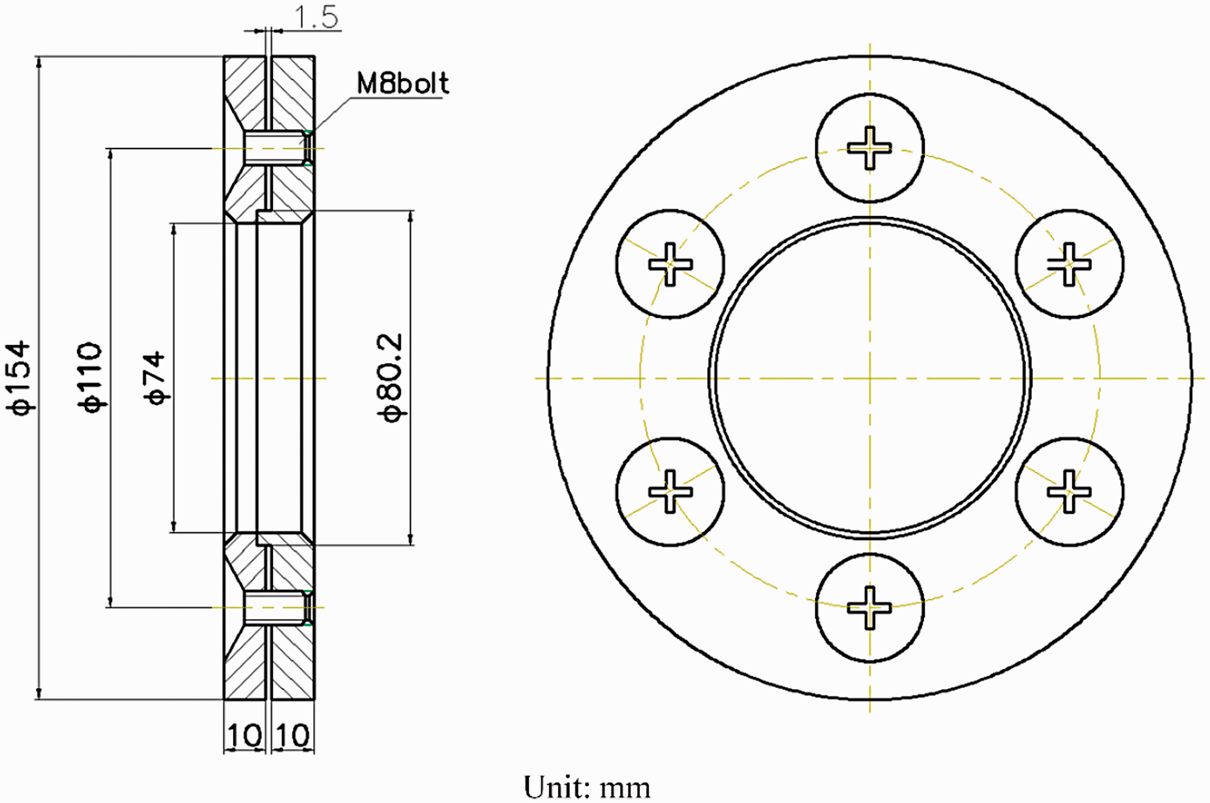
Schematic diagram of the fixture apparatus.
Theoretically, when the boundary condition is assumed as clamped, the deflection and derivative of the edge are zero. As the support rim cannot be perfectly rigid, this boundary condition is actually an idealized assumption. For a realistic experimental study, the relaxed clamped boundary condition makes the resonance frequency of the sample lower than the idealized perfect clamped boundary condition. 24
At the first resonance frequency, the incident SPL is kept at 114 dB (10 Pa), and the harvester’s output voltage versus load resistance is shown in Figure 13.
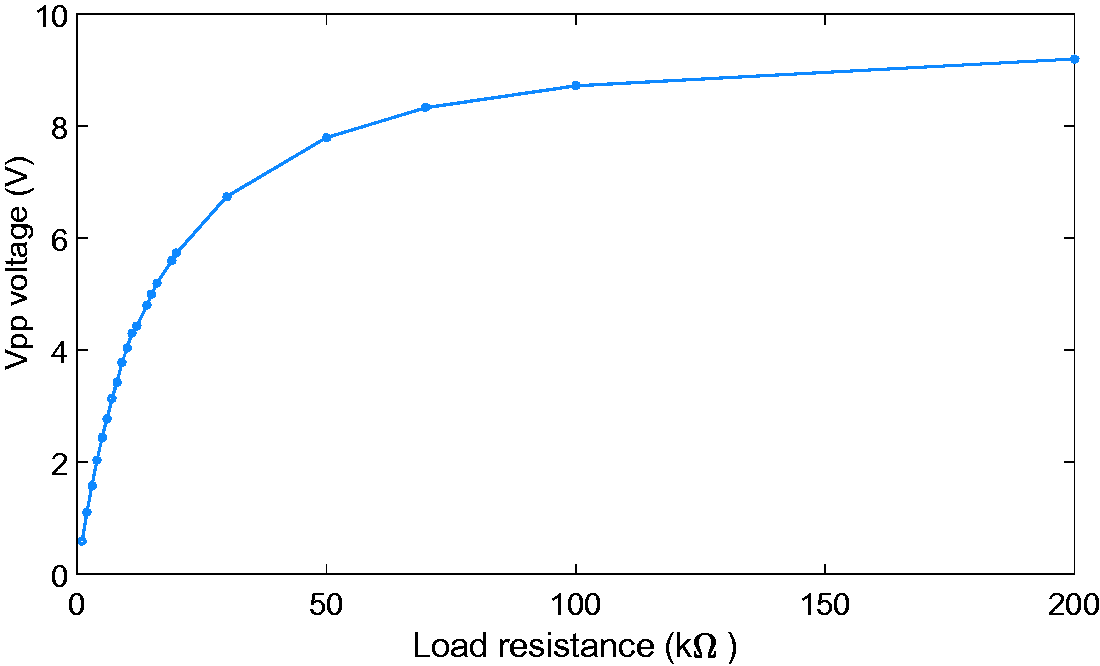
Harvester’s output voltage versus load resistance.
According to equation (8), the corresponding harvested power value 
The corresponding result is plotted in Figure 14.
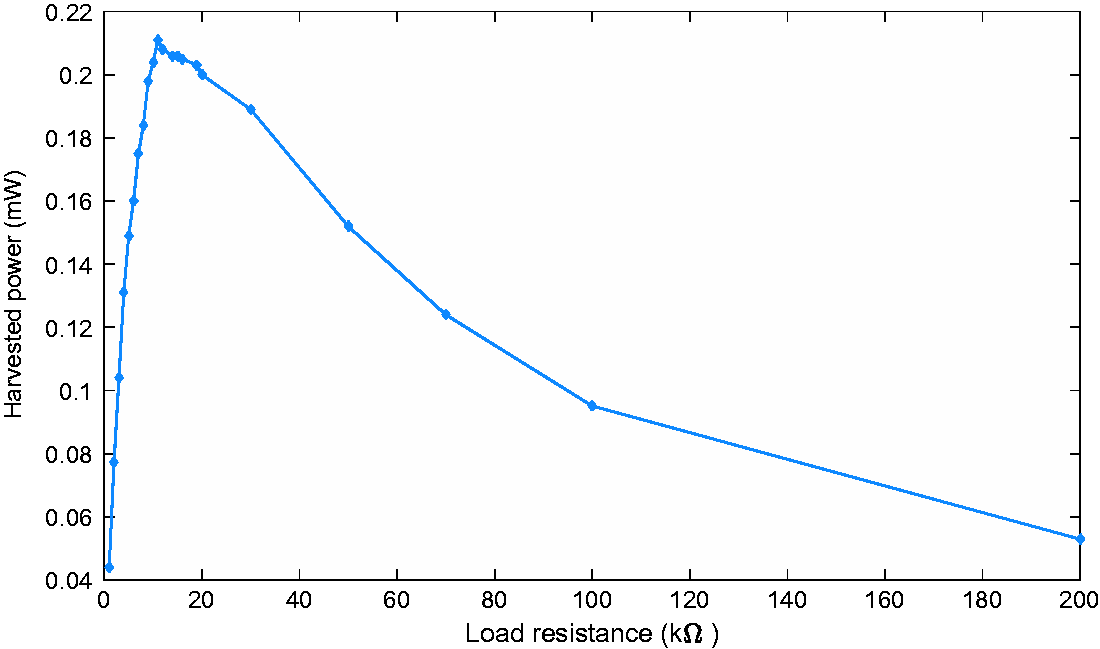
Harvester’s output power versus load resistance.
The experimental result shows that 0.21 mW maximum electrical power can be harvested. The measured power has almost the same value as predicted by the numerical simulation. The incident acoustic power is 1 mW; therefore, the acoustical–electrical conversion efficiency is 21%.
To further improve the electrical conversion performance, it would be favorable to boost the piezoelectric material’s performance. The reason is that for the piezoelectric 31 mode energy harvesting application, the corresponding electromechanical coupling factor 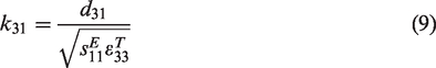
According to equation (9), a large value of
With respect to the sample’s strength, the PZT-5H patch is the system’s most fragile part. The PZT-5H material is easy accessible, possessing satisfying piezoelectric properties and low fabrication cost, these merits make it being extensively used in the piezoelectric energy harvesting studies. However, as it belongs to ceramic category, it has the brittle drawback and cannot bear large substrate deformation. This drawback limits its application under severe mechanical excitation. For the acoustic energy harvesting (AEH) application, as the energy intensity is usually not strong enough, the proposed structure’s durability can be guaranteed.
As a single metastructure cell’s harvested power value can reach 0.21 mW, it would be very interesting to fabricate multiple cells as a meta-plate for large electrical power generation, and we are confident that this work will be carried out in the near future.
Conclusion
In this study, a metastructure with both noise isolation and energy harvesting abilities is proposed. Compared with the rubber-based substrate, metallic-based substrate can omit the tension process and provide stronger durability for practical engineering application. The structural parameter’s influence on the sample’s vibro-acoustic properties and energy harvesting performance are investigated via the finite element method. Simulation results indicate that the incident sound wave intensity, the shape of the proof mass, the type of substrate material, and the thickness of the substrate all have substantial influence on the metastructure. The configuration with the best energy harvesting ability is also testified through experimental study, which shows competitive performance comparing with previous AEH studies.
Substantial noise isolation at the first anti-resonance frequency and efficient acoustic energy harvesting at the first resonant frequency can be achieved via the proposed metastructure. Although at the efficient energy harvesting frequency, the corresponding sound isolation performance nearby can be unsatisfying. This drawback could be overcome if multiple layers’ configuration is adopted, where each layer has different local resonant property, improving the overall sound isolation performance and broadening the energy harvesting frequency band. The proposed multi-functional metastructure provides new insights for acoustic energy manipulation and utilization. These analysis results may be used as guidance for further metastructure-based acoustic energy harvesting studies.
Footnotes
Acknowledgments
The authors sincerely thank the reviewers and editor for their valuable comments and suggestions that have led to the present improved version.
Declaration of conflicting interests
The author(s) declared no potential conflicts of interest with respect to the research, authorship, and/or publication of this article.
Funding
The author(s) disclosed receipt of the following financial support for the research, authorship, and/or publication of this article: This research was sponsored by the Natural Science Foundation of Jiangsu Province (Grant No. BK20160895), the National Natural Science Foundation of China (Grant Nos. 61372044, 61701250, 11604158), NUPTSF (Grant Nos. NY215009, 215032, 217029), and the Natural Science Foundation of the Jiangsu Higher Education Institutions of China (14KJA510002).