
Abstract
This paper proposes a vibration model for modal analysis and vibration control of a vertical cable-dual tuned mass damper (C-DTMD) coupled system. The proposed model introduces several non-dimensional parameters to describe the in-plane vibration of the coupled system. Moreover, the phenomenon of modal split is comprehensively studied to present the complex vibration modes. Parameter analysis is conducted to show the influence of length ratio, mass ratio, damping ratio, and frequency ratio on vibration reduction. In addition, the theoretical model is verified using finite element methods. A practical vertical cable in Jiangyin Bridge with designed wind loads is chosen as a numerical example. The results show that DTMD devices can effectively reduce the modal vibration and have great potential for multi-mode vibration control of vertical cables in suspension bridges. The proposed model can accurately describe the in-plane vibration modes of C-DTMD systems and provides a basis for the optimal design of damper parameters.
Introduction
Vertical cables have been widely used in suspension bridges as the main load bearing structures.1–3 The operating conditions of vertical cables are very important for the overall safety of bridges. With the development of advanced production technology and design theory, the length of vertical cables in suspension bridges has been remarkably enhanced in recent decades. However, vertical cables are usually made of materials that have high-strength steel wires but relatively light mass. The cables may become more sensitive to wind or rain-induced vibration due to their higher structural flexibility. Cables may encounter undesired vibrations, including vortex-induced vibration, buffeting, and galloping.4–7 The vibration-induced impact force and fatigue loads may cause damage to structures, jeopardizing the integral safety of suspension bridges.8–10 Therefore, it is necessary to reduce the vibration of cable structures in bridge engineering to ensure its safety.
Currently, various vibration control methods, including active control, passive control, semi-active control, and hybrid control, have been developed to reduce the vibration of cable structures. The vibration control strategy can be divided into the following categories: shape modification,11,12 cross-ties methods,13–15 viscous dampers,16,17 tuned liquid dampers, 18 inertial mass dampers, 19 magnetorheological dampers,20,21 and tuned mass dampers (TMD).22–25 Compared with the other methods, the TMD method has been demonstrated to be an effective method for reducing vibrations in bridges due to its low costs, flexible installation position, and reliable damping effect. The vibration energy can be transferred from host structures to additional TMD devices.25,26 It can realize the passive or semi-active control of structures with many successful cases. For example, Di et al. 27 designed an additional device to suppress the vibrations of high-order modes using TMD method. Pacheco et al. 28 proposed a universal estimation curve that related the modal damping ratio of the cable with several parameters, including attached dampers, mode numbers, damper sizes, the damper locations, and cable parameters. The mass of the damper was ignored in this study. Wu and Cai 29 designed a magnetorheological TMD device. The parameters were analyzed to show the effect of the positions, mass and damping on the dynamic characteristics of the system in terms of modal damping. Liu et al. 23 designed a pounding TMD to reduce the modal vibration of an experimental stay cable with a prominent damping effect. In short, the limitations in using TMD to control cable vibration are mainly two points. Firstly, vibration control by TMD is only effective within a specific frequency region. The regulation capability is limited to single modal vibration, which may not be suitable for multi-modal vibration control. Secondly, the optimal deturning and damping effect of C-TMD coupled structures is difficult to realize in real engineering based on the single-degree-of-freedom model. It is of great importance to know the effect of each factor to design the optimal parameter of the TMD device.
To address this problem, dual tuned mass dampers (DTMD) are used in many civil engineering due to their superb robustness in frequency tuning.30–32 In this paper, a vibration model of a vertical cable-dual tuned mass dampers (C-DTMD) system is established. Several non-dimensional parameters are introduced to describe the vibration characteristics of coupled systems. In addition, the parameters were analyzed based on the influence of mass ratio, damping ratio, and frequency ratio. Moreover, a numerical model using the finite element method is presented to verify the proposed model. The results first show the vibration characteristic of C-DTMD devices, which is useful for multi-modal vibration control of cable structures.
The rest of this paper is organized as follows. The Vibration model section formulas a vibration model of C-DTMD systems. The Modal damping analysis of a C-DTMD system section discusses the phenomenon of modal split and related influencing parameters, including length ratio, mass ratio, frequency ratio, and damping ratio. The Numerical verification section establishes a numerical example under wind loads based on the finite element model to verify the proposed model. Finally, the conclusions of this study are drawn in the Conclusions section.
Vibration model
Dynamic modal of a vertical cable
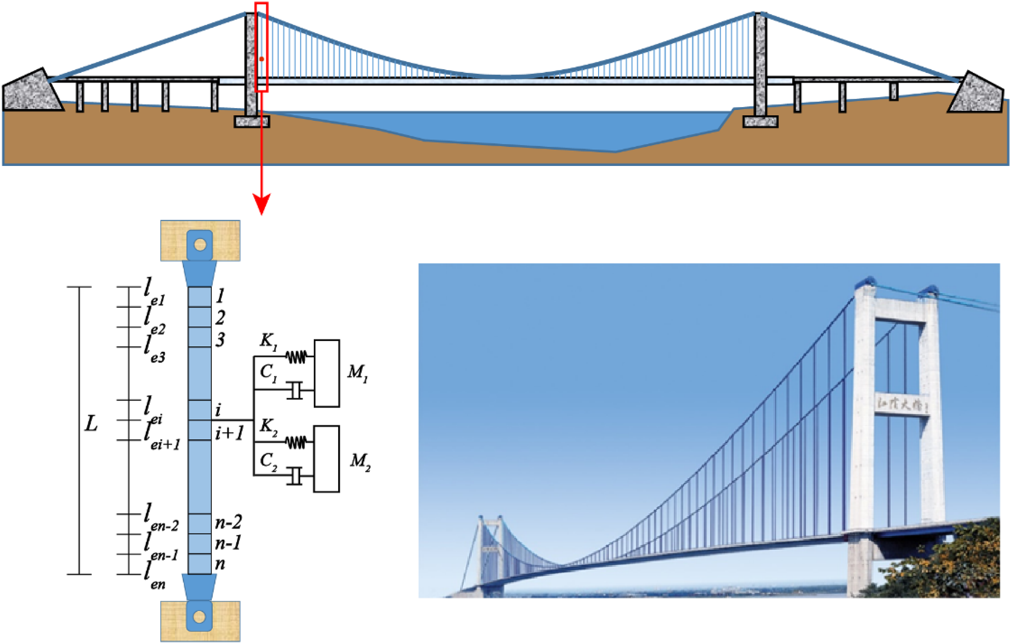
The tension of a vertical cable follows a uniform linear distribution under the influence of gravity, as shown in Figure 1. The vibration model of cables is expressed in the equation below
33
In-plane vibration of a vertical cable.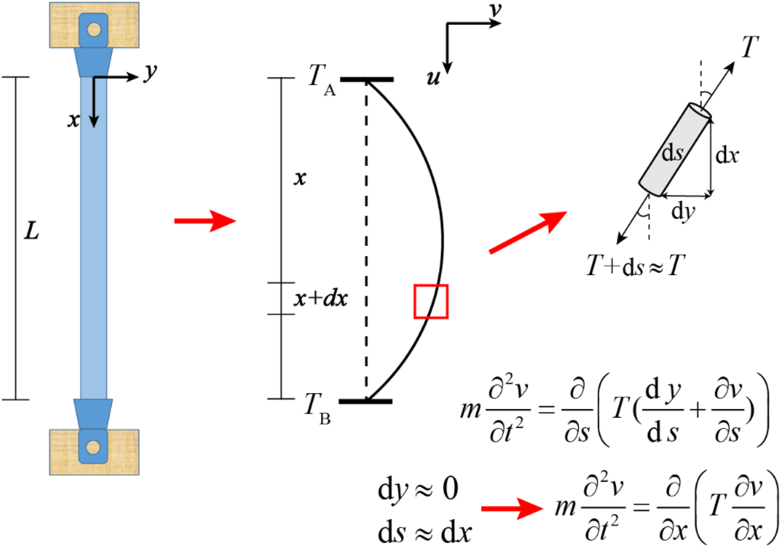


where


The non-dimensional parameter

The roots of equation (7) are the natural frequencies of the vertical cable systems. It can be numerically calculated by Maple or Mathematica. Suppose that the n-th root of equation (7) is defined as

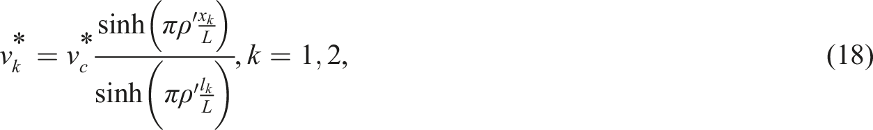
Combining equation (8) and the definitions of non-dimensional parameter

Hence, the relative error is calculated as follows

It is shown in equation (10) that the error is controlled by the non-dimensional parameter
C-DTMD systems
The vibration model of C-DTMD systems is shown in Figure 2. Without loss of generality, it is assumed that In-plane vibration of a vertical cable with dual tuned mass dampers.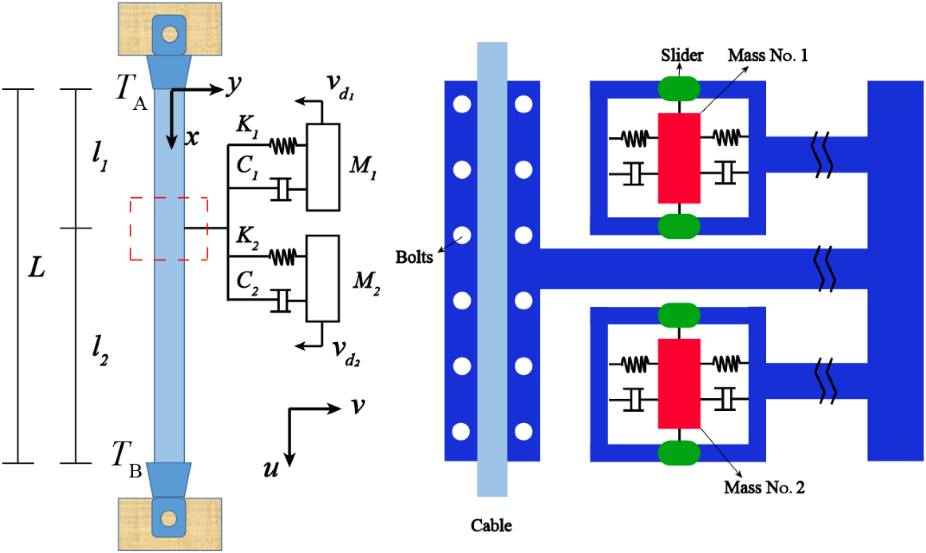


where


Similarly, substituting equation (14) for equations (12) and (13) yields


Substituting equations (18) and (19) for equation (12) yields

The non-zero solution of equation (21) is the natural frequency of C-DTMD systems, which can be taken as an eigenvalue problem. The i-th eigenvalue


It can be seen from equation (23) that the system becomes over-damped, that is, modal damping

Modal damping analysis of a C-DTMD system
Modal Split
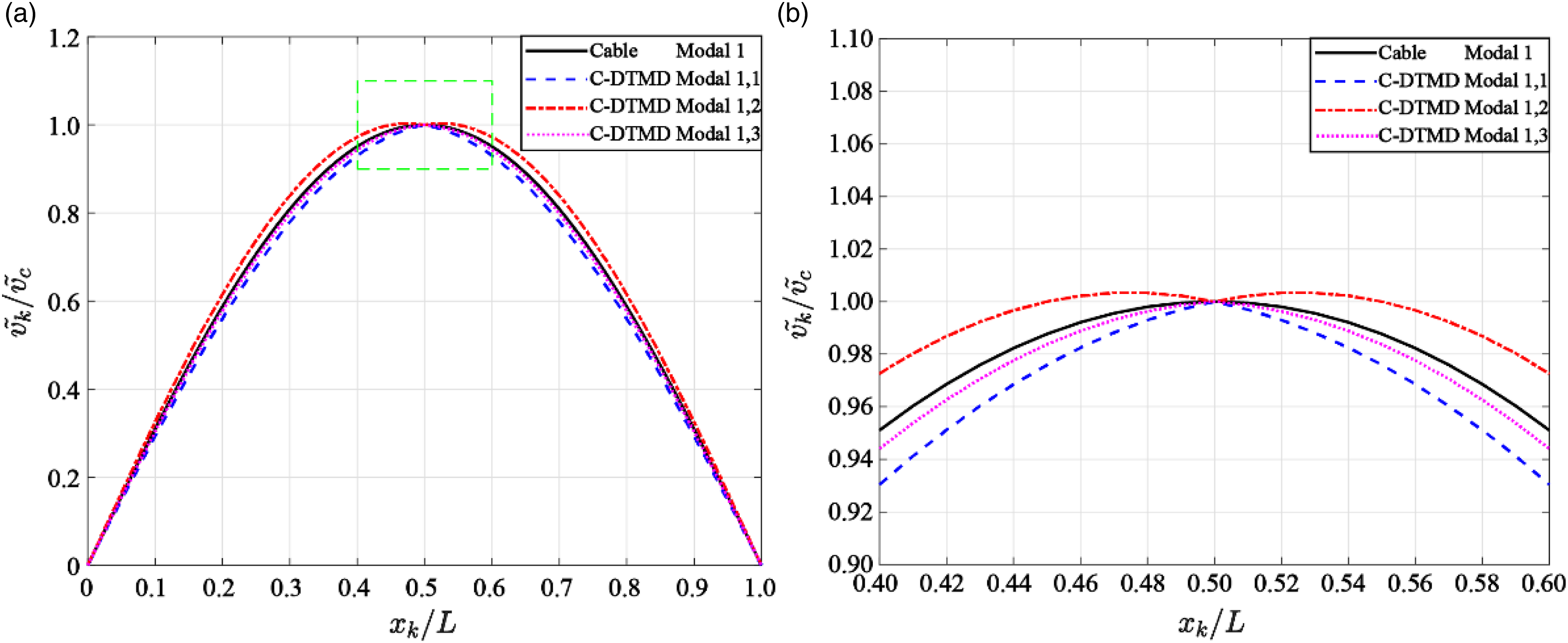
The vibration modes can be solved by equation (18) after the eigenvalue Modal split of C-TMD systems. (a) Overall view and (b) regional enlarged view. Modal split of C-DTMD systems. (a) Overall view and (b) regional enlarged view.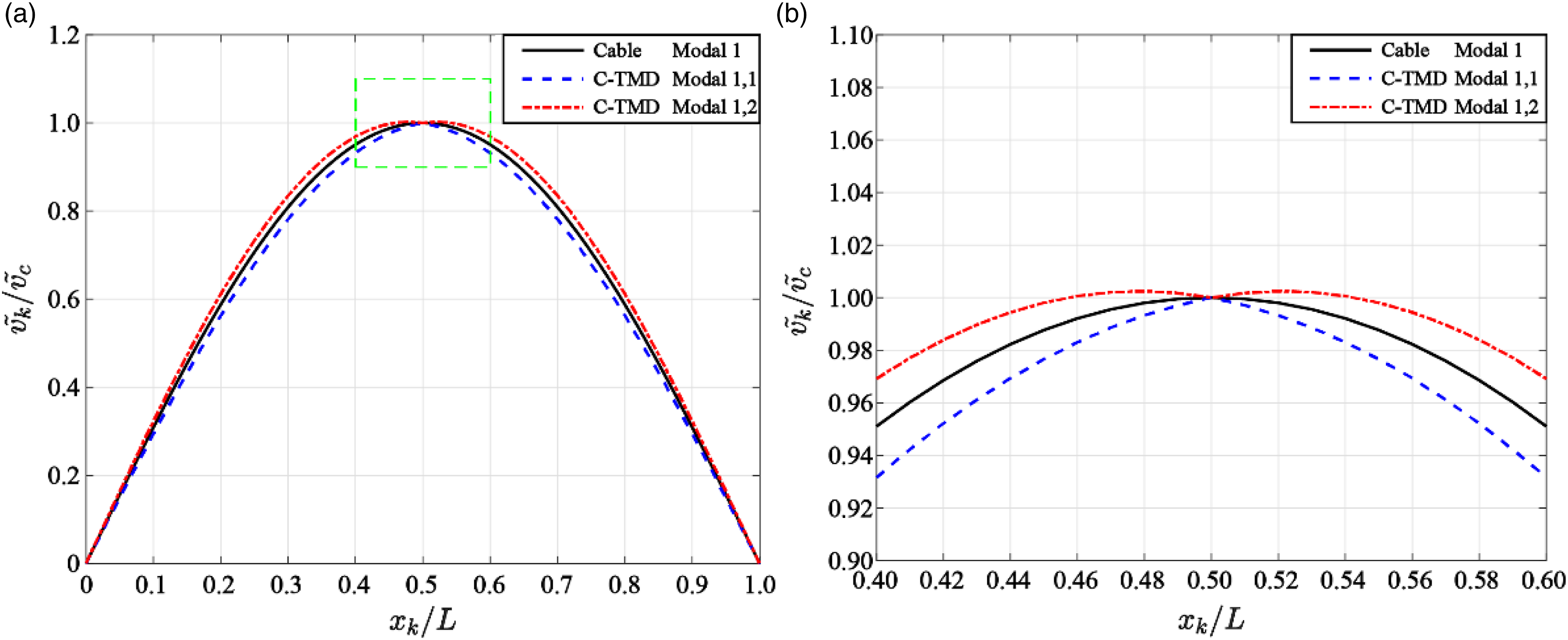
Parameters analysis
Basic parameters and value range of DTMD devices.
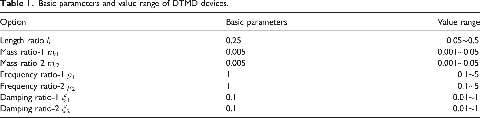
Length ratio
The variation of the modal damping is shown in Figure 5 with different length ratios. The C-DTMD system is tuned to the first-order modal frequency. Thus, the modal damping of the higher-order is much lesser than that of the first-order. It is obvious from Figure 5(a) that the modal damping is very small when the installation location is close to the anchor region. The modal damping increases significantly to 0.039 when the location moves to about 1/4 span. Afterward, the modal damping remains relatively stable between 1/4 span and mid-span. In this region, the modal damping is slightly larger than 0.040. The length ratios of viscous dampers are generally 0.02 to 0.05 near the anchor region. The modal damping of viscous dampers is about 0.025.
34
Influence of length ratio on 1st order modal damping. (a) Overall view and (b) regional enlarged view.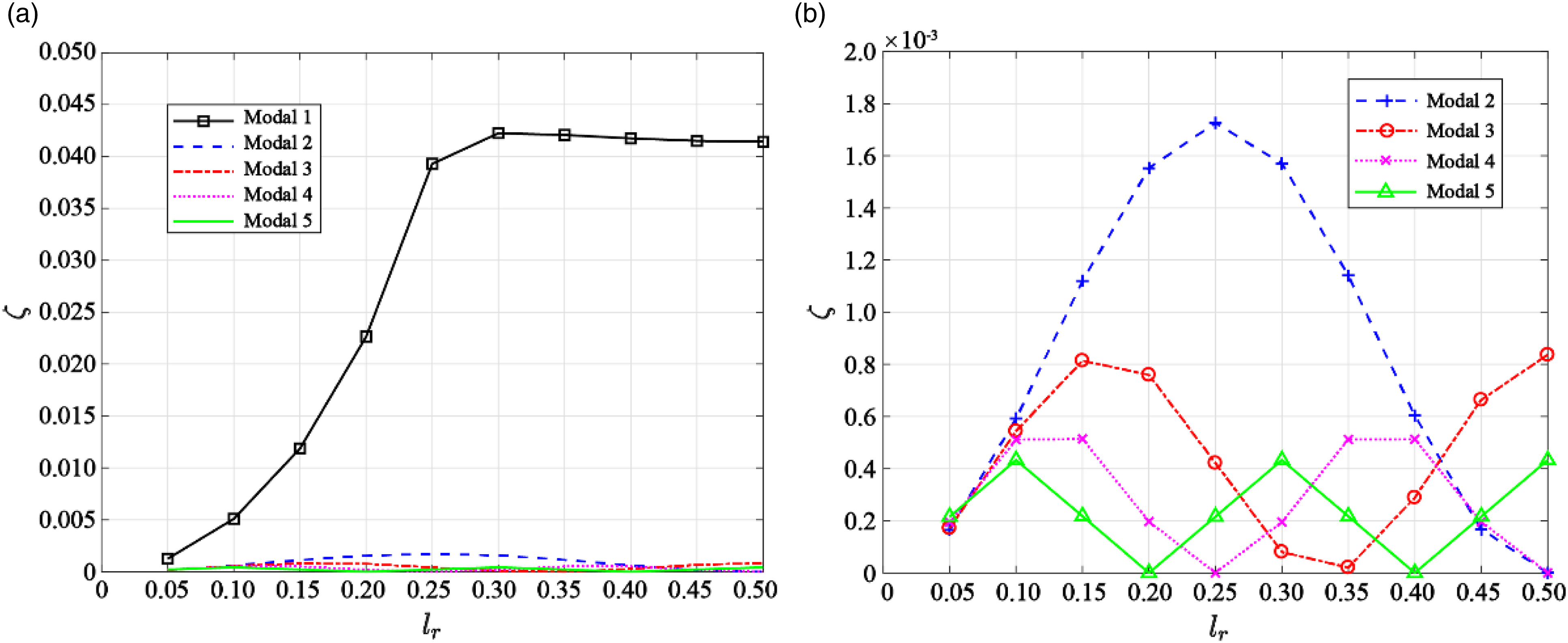
Figure 5(b) shows the regional enlarged view to reflect the high-order modal damping. It can be found from the figure that the peak value of the n-th modal damping is located at
The C-DTMD system is then tuned to the second-order modal frequency. The second-order modal damping is much greater than the other modes, as shown in Figure 6. Meanwhile, the second-order modal damping near the 1/4 span is much greater than other situations. Influence of length ratio on 2nd order modal damping. (a) Overall view and (b) regional enlarged view.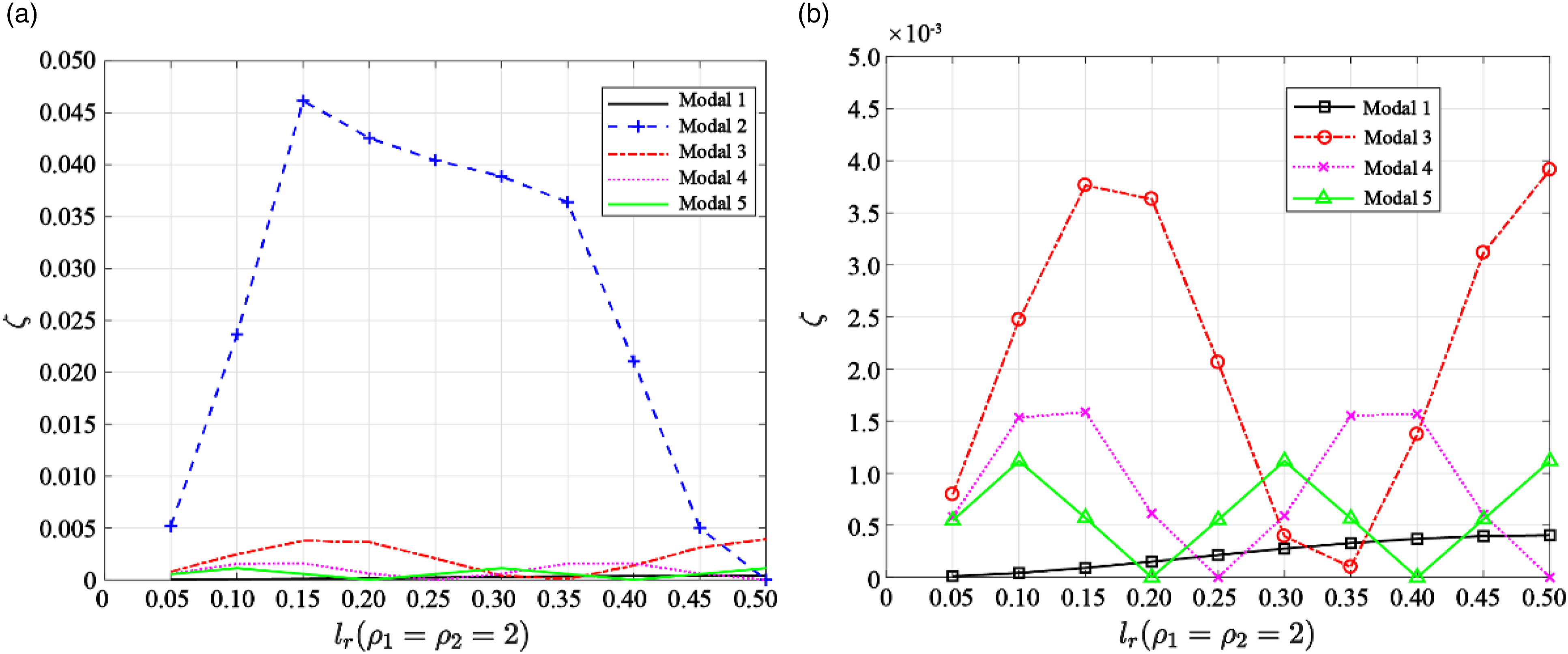
Mass ratio
Generally, the mass ratio is within 5% because DTMD devices cannot be designed to be too heavy. For the overall balance, it is assumed that the two masses are equal, that is,
The change of the first five-order modal damping is shown in Figure 7. The four-order modal damping is identically equal to zero because the 1/4 span is the node. It can be seen from the figure that the first-order modal damping of the system increases greatly from zero to the peak value of 0.044 as the mass ratio increases from 0.10% to 0.65%. Then, the first-order modal damping starts to decrease slowly with the increase in the mass ratio. This is because the frequency ratio is assumed to be a constant instead of decreasing accordingly. Therefore, it does not meet the optimal design principle of dampers. The modal damping may decrease under these conditions. Effect of mass ratio on modal damping of C-DTMD systems.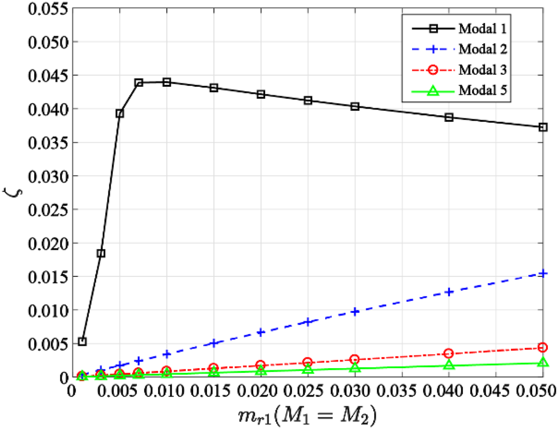
Damping ratio
The damping ratio can control the energy dissipation characteristics of the C-DTMD system. The two damping ratio of DTMD is also assumed to be the same to reduce the complexity. The damping ratios that vary from 0 to 1 are numerically studied in order to provide a comprehensive understanding of the C-DTMD system, although such a large damping ratio may be impractical. The results of the first five modes are shown in Figure 8. The maximum value of the first modal damping is about 0.040 when the damping ratio equals to 0.095. The second-order modal damping increases to 0.006, while the other high-order modes are much smaller than that of the first two modes. Effect of damping ratio on modal damping of C-DTMD systems.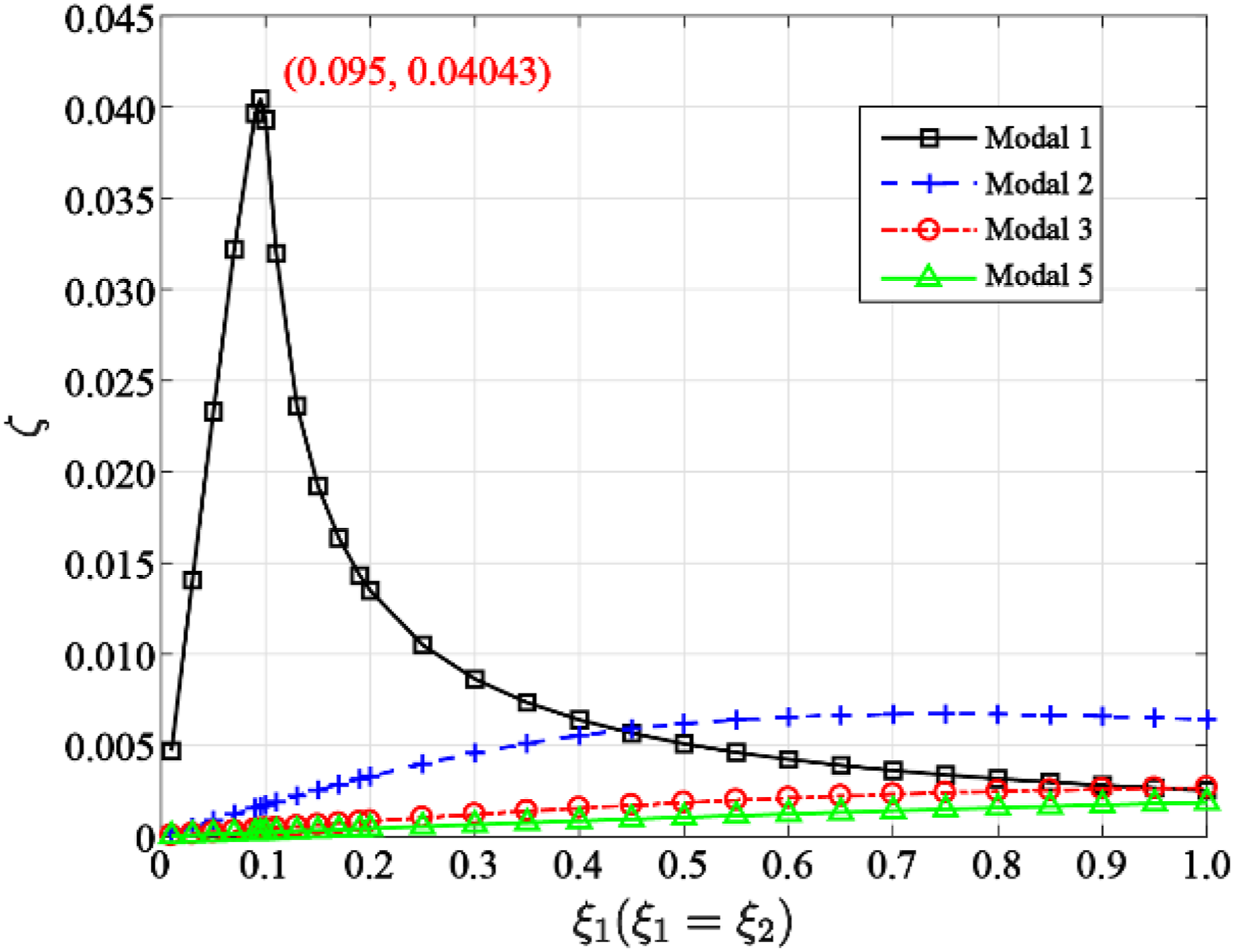
On one hand, the damper cannot effectively dissipate vibration energy if the damping ratio of the damping device is too small. The overall damping effect of the C-DTMD system is not obvious under this condition. On the other hand, excessive damping ratio will weaken the movement of the spring, which is equivalent to the damper being rigidly connected to the sling.
Frequency ratio
The frequency ratio has an essential effect on the modal damping of systems. Compared to TMD, DTMD systems have two independent spring devices. This can make them generate two different frequency ratios, which is an outstanding advantage in vibration control. Therefore, the influence of frequency ratio on modal damping is discussed in this section.
Case 1: Same frequency ratios
Firstly, the two frequency ratios of DTMD are assumed to be the same. The corresponding modal damping is shown in Figures 9 and 10, respectively. The four-order modal damping is equal to zero due to the 1/4 span being the node. Each order modal damping increases to the peak value when the frequency ratio is equal to the corresponding order. Effect of frequency ratio on modal damping of C-DTMD systems ( Regional enlarged view of the (a) first- and (b) second-order modal damping.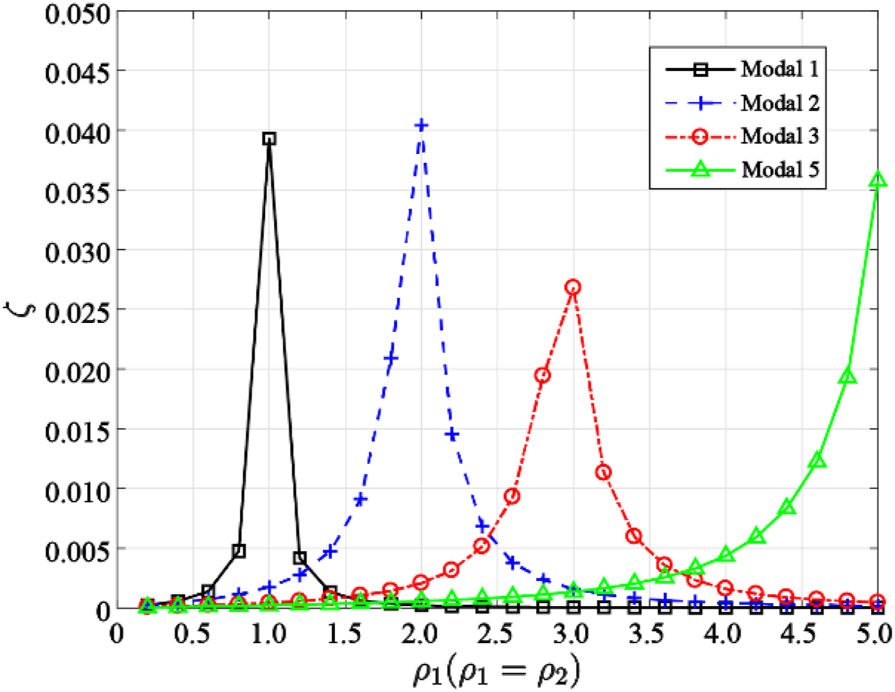
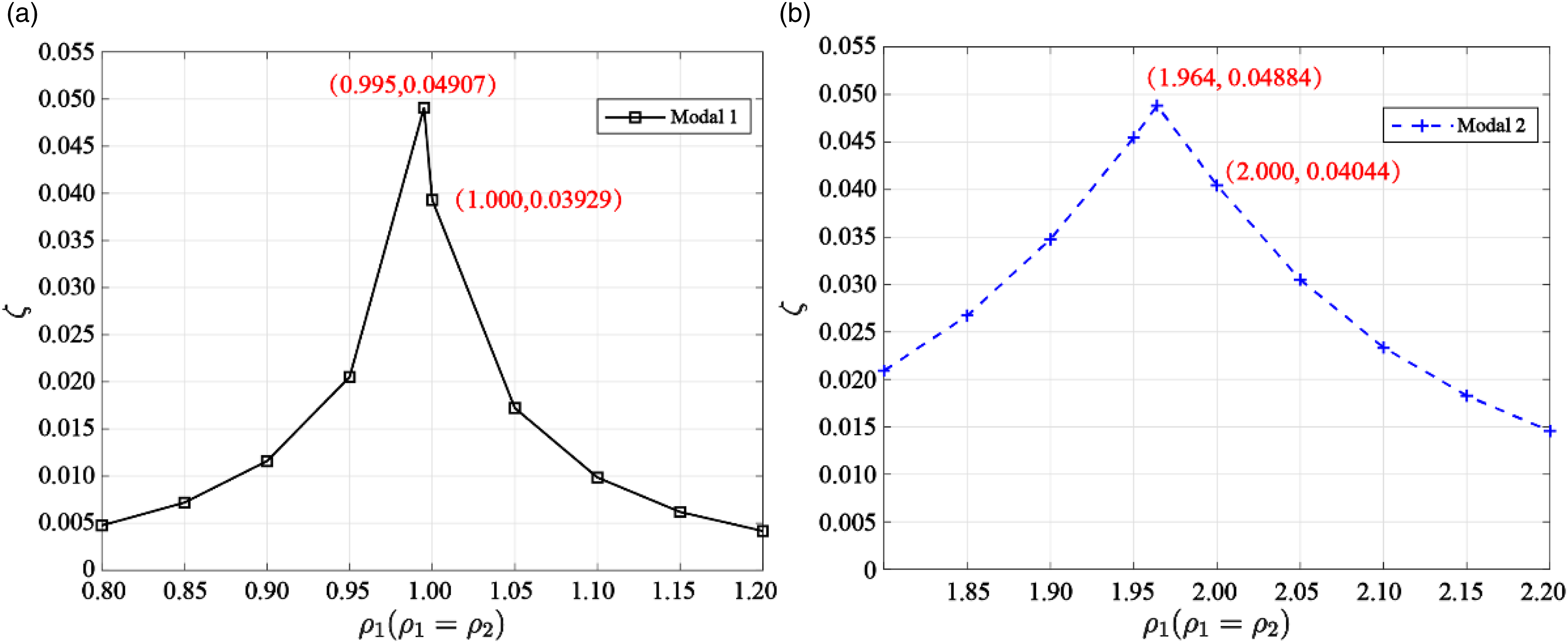
According to the optimal damping theory, 35 the natural vibration frequency of the damper generally needs to be adjusted to be slightly lower than the natural vibration frequency of the cable. Therefore, it is shown in Figure 10(a) that the first-order modal damping increases to 0.04,907 as the frequency ratio increases to 0.995. Similarly, the second-order modal damping increases to 0.04,884 when the frequency ratio is equal to 1.964, as shown in Figure 10(b).
Case 2: Different frequency ratios
The maximum modal damping is not the same as the natural frequency in case Regional enlarged view of the first-order modal damping. (a) 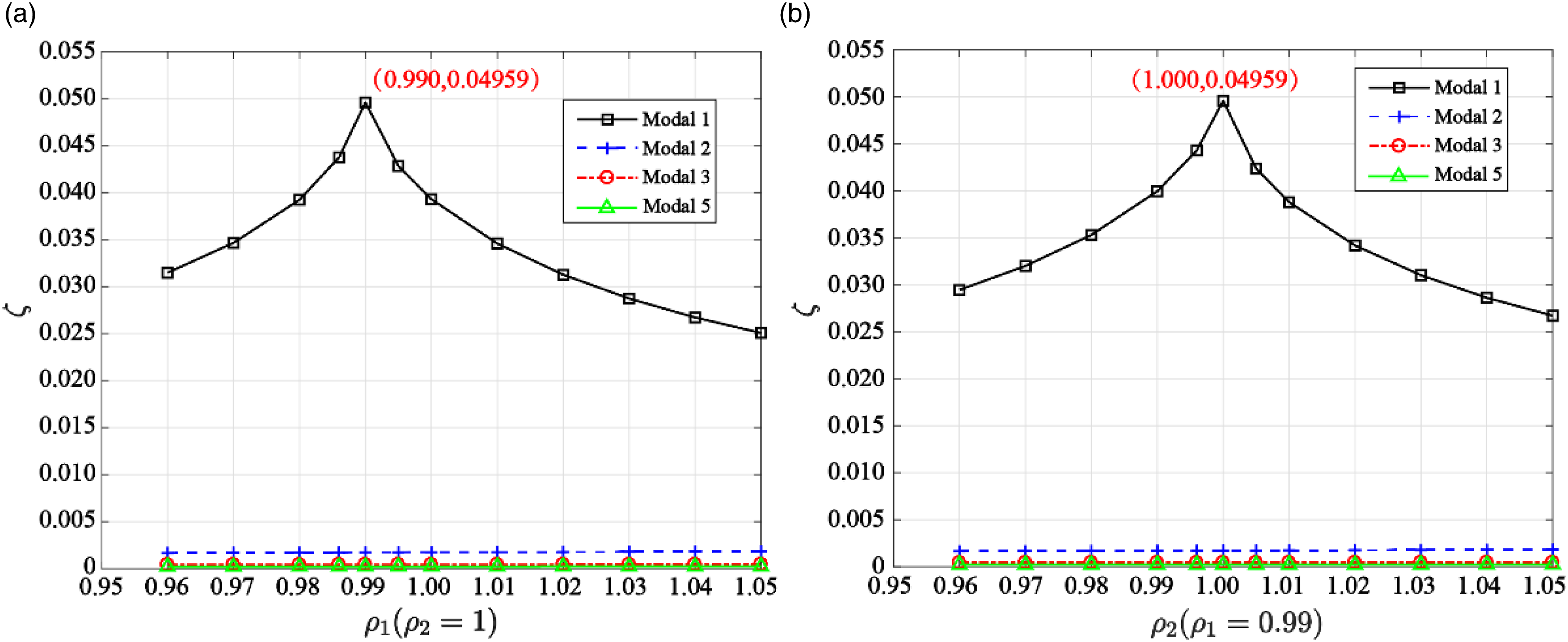
In addition, the frequency ratios Multi-modal vibration control using different frequency ratios (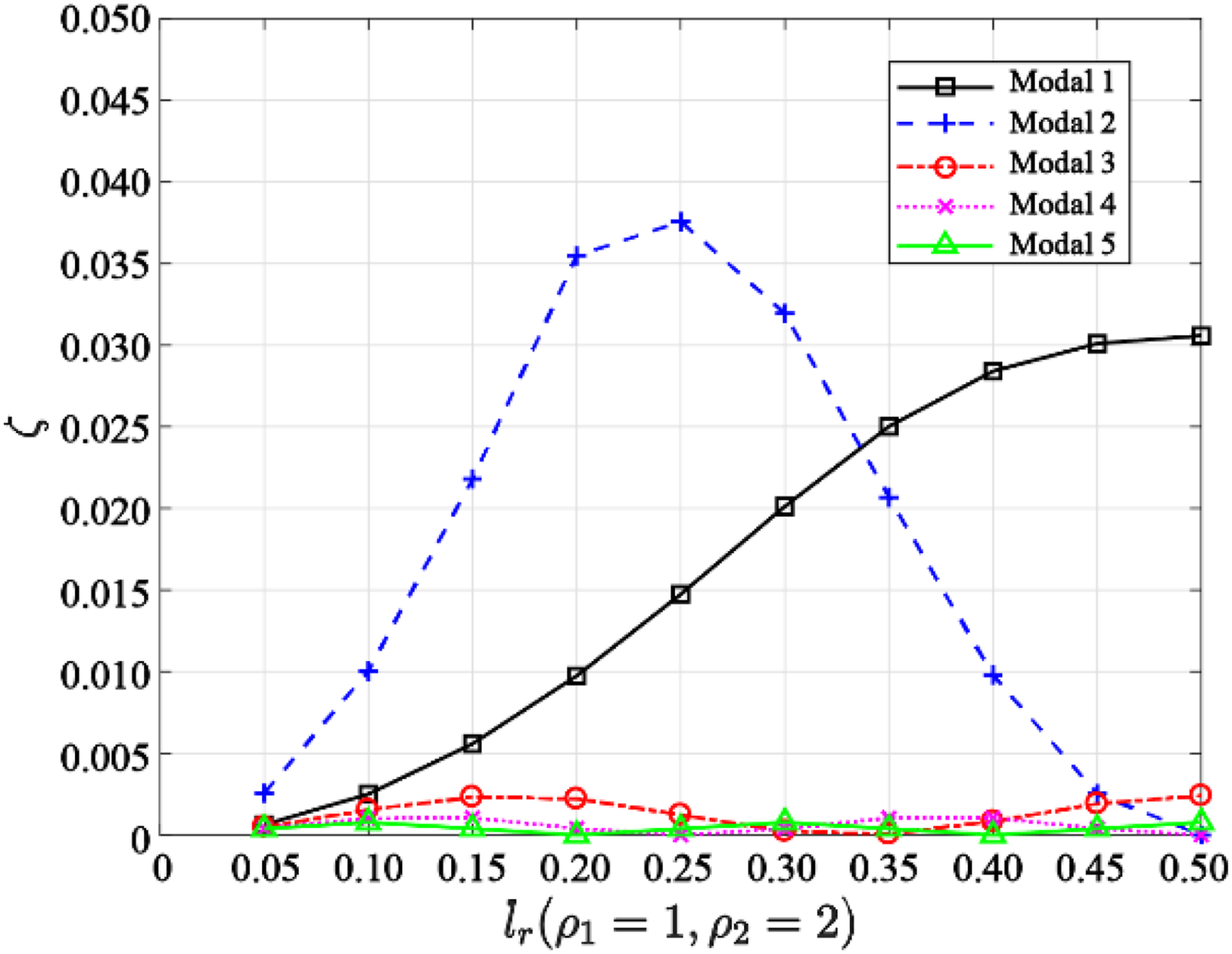
Numerical verification
A numerical modal is established in this section to verify the theoretical results of C-DTMD systems under wind loading.
Numerical model of a C-DTMD system
The finite element method is used to solve the vibration equations of C-DTMD systems. For cable vibration, the local mass and stiffness matrix of a cable can be expressed as

A cable of Jiangyin Bridge is chosen as the numerical example, as shown in Figure 13. The cable is the No. 1 cable of the bridge and is close to the north tower. The cable length is 136.561 m, which is the longest cable of the bridge. The mass per unit length of the cable is about 18.49 kg/m. One accelerometer is installed on the 1/4 span of the cable. The tension of the cable can be calculated by Numerical example of a vertical cable in Jiangyin Bridge.
Modal analysis
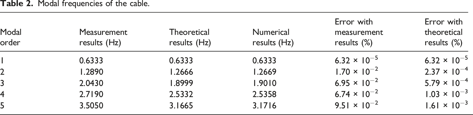
Modal frequencies of the cable.
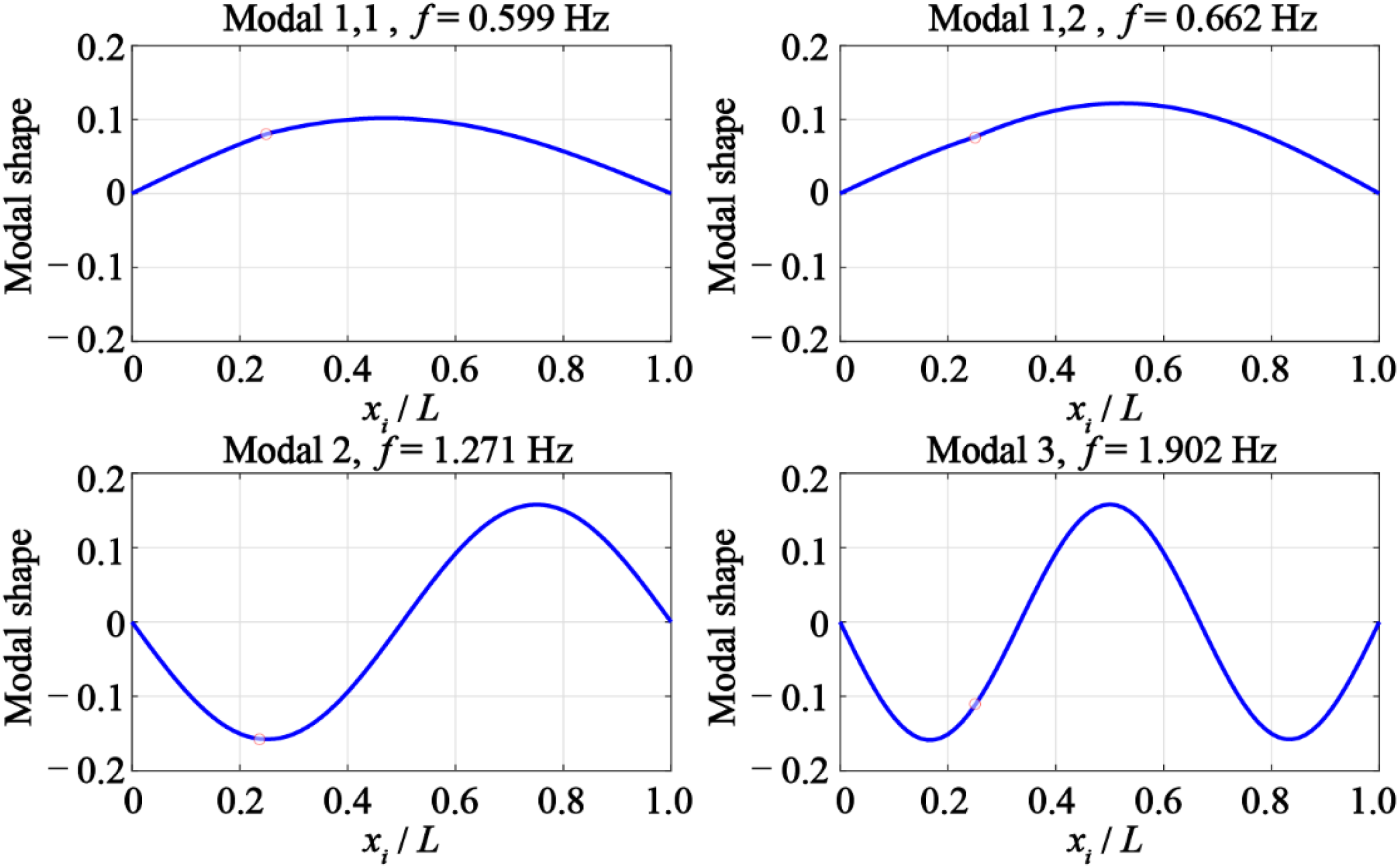
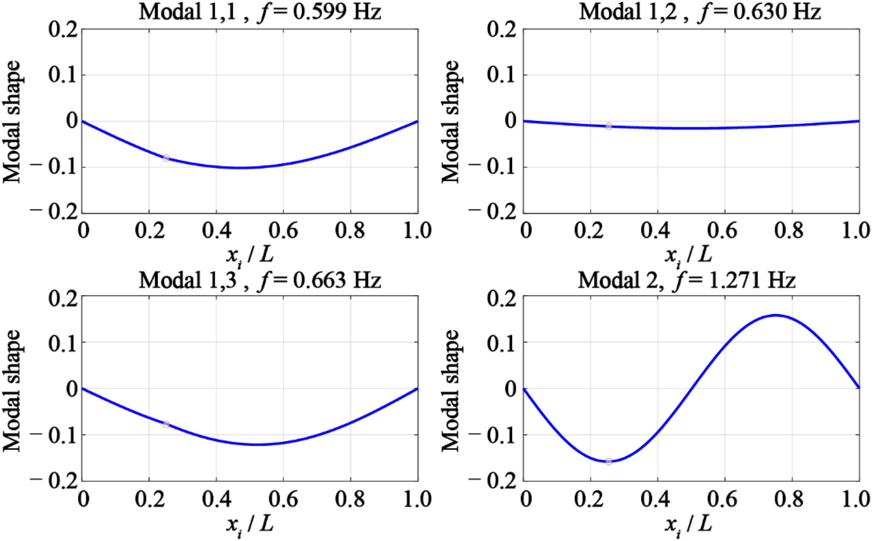
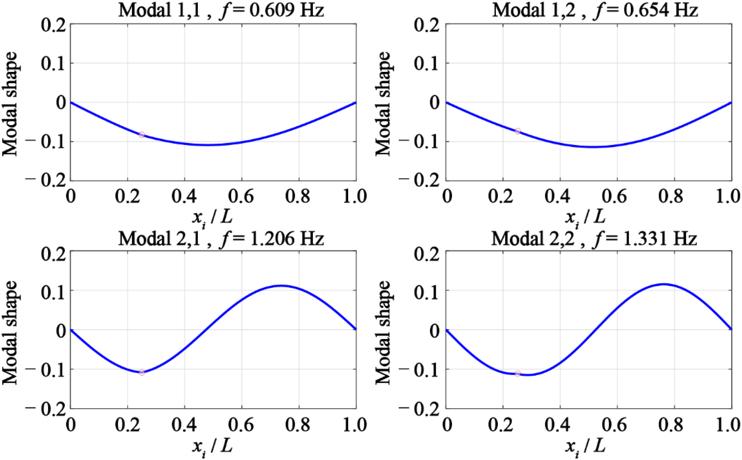
The first four-order modal shapes of the cable are shown in Figure 14 as a benchmark. Moreover, the overall modal shapes are calculated by the finite element methods. DTMD is introduced with different frequency ratios, as discussed in Section 3.2.4. Similarly, three cases are separately verified using numerical examples. (i) Case 1: Frequency ratio First four-order modal shapes of the cable. First four-order modal shapes of the C-DTMD systems ( First four-order modal shapes of the C-DTMD systems ( First four-order modal shapes of the C-DTMD systems (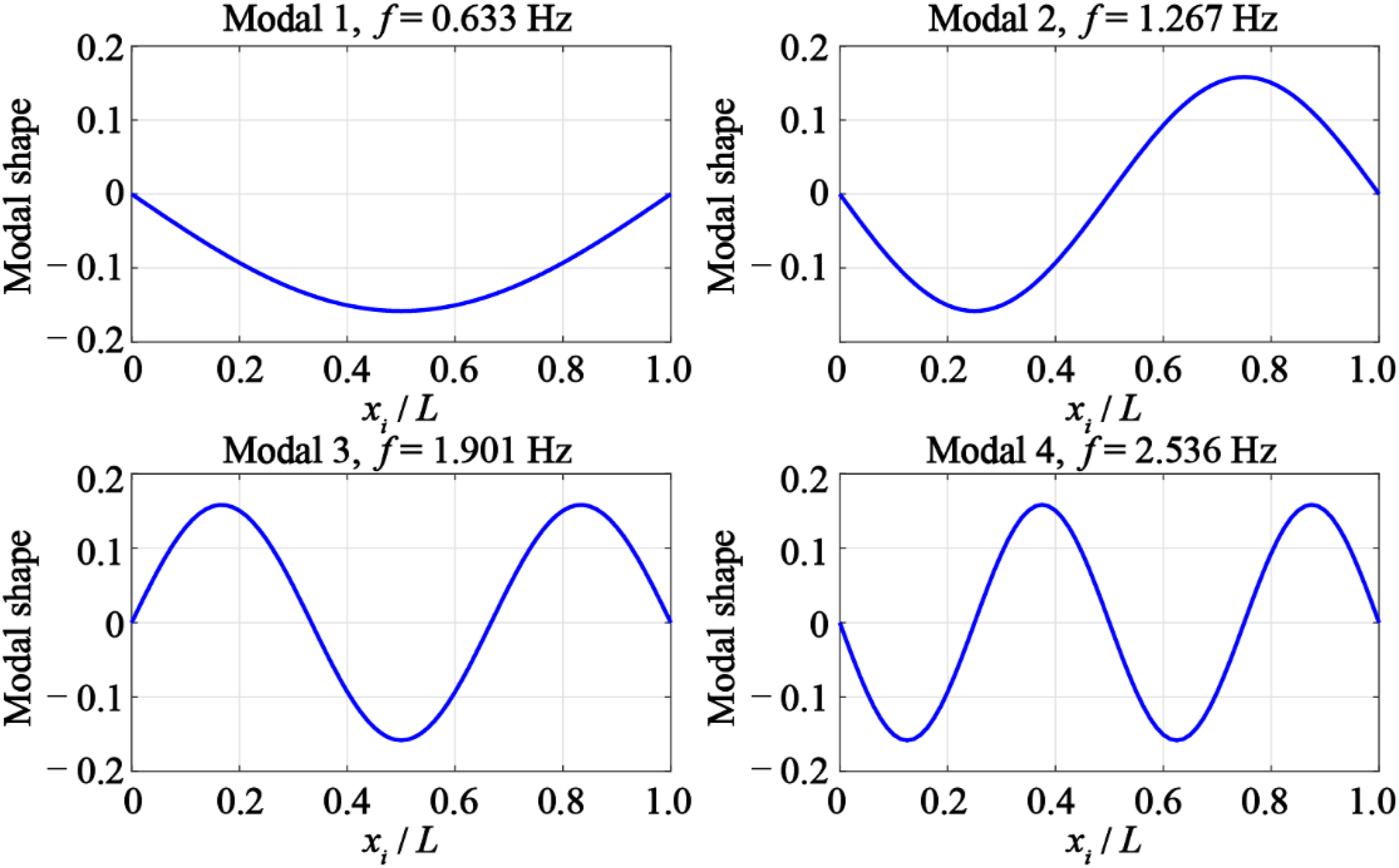
Transient dynamic analysis
The transient dynamic analysis is conducted to verify the vibration control effect under wind loads.
Wind loads
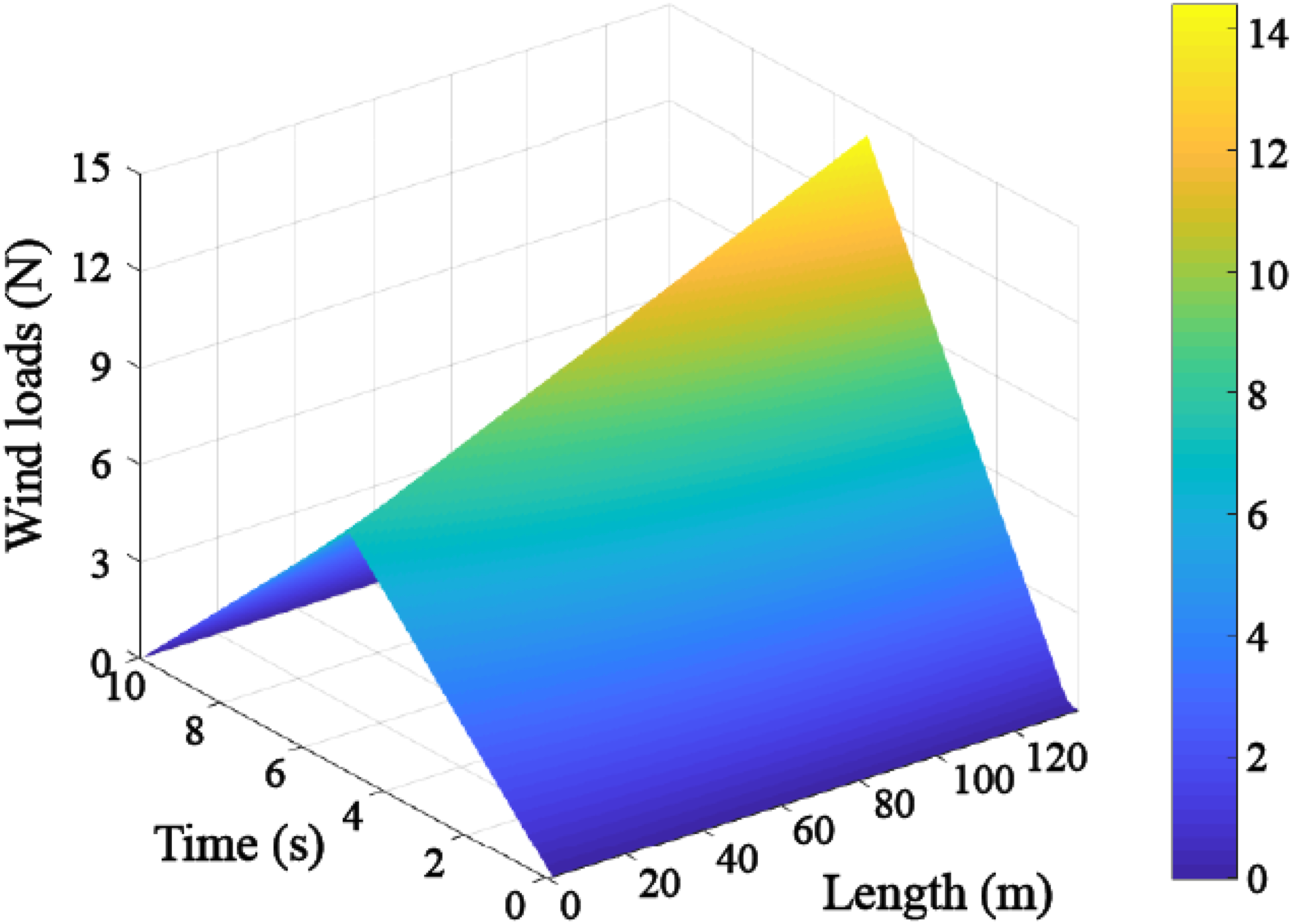
Wind-induced vibration is the most common form of cable vibration. The Reynolds number Designed wind loads of each element in numerical model.


Parameters analysis
The parameters analysis is conducted to validate the accuracy of the proposed theoretical model in this section. The numerical results are compared with the modal damping analysis in Section 3. Without loss of generality, the displacement responses of 3/8 span are chosen as the reference point.
Length ratio
The transient dynamic analysis is conducted to verify the vibration control effect. The frequency ratio is designed as 1 to reduce the first-order modal vibration. The displacement of the reference point is shown in Figure 19. It is shown in Figure 19(b) that the vibration amplitude is not weakened if the DTMD is not installed on the cable. The damping effect is enhanced in turn as the length ratio of the DTMD moves to 1/2. Displacement of the reference point under different installation positions of DTMD devices. (a) Overall view and (b) 10–40 s regional enlarged view.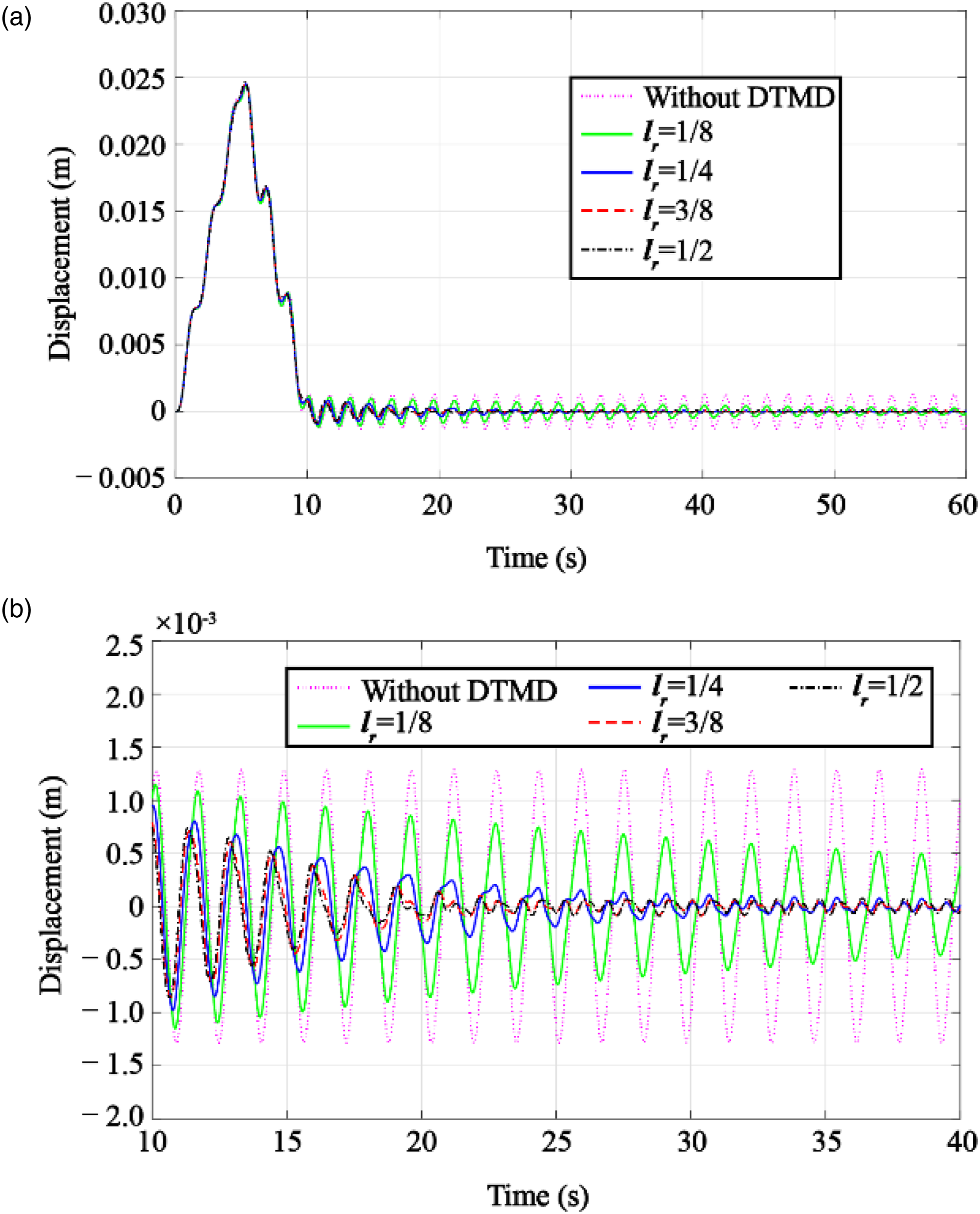
The frequency spectrum of the displacement response is shown in Figure 20. The amplitude of the first-order frequency decreases as the length ratio moves to 1/2. The improved effect of the damper is not obvious when the length ratio is larger than 1/4, corresponding to the results shown in Figure 5. Frequency amplitude of the measured displacement. (a) Overall view and (b) regional enlarged view.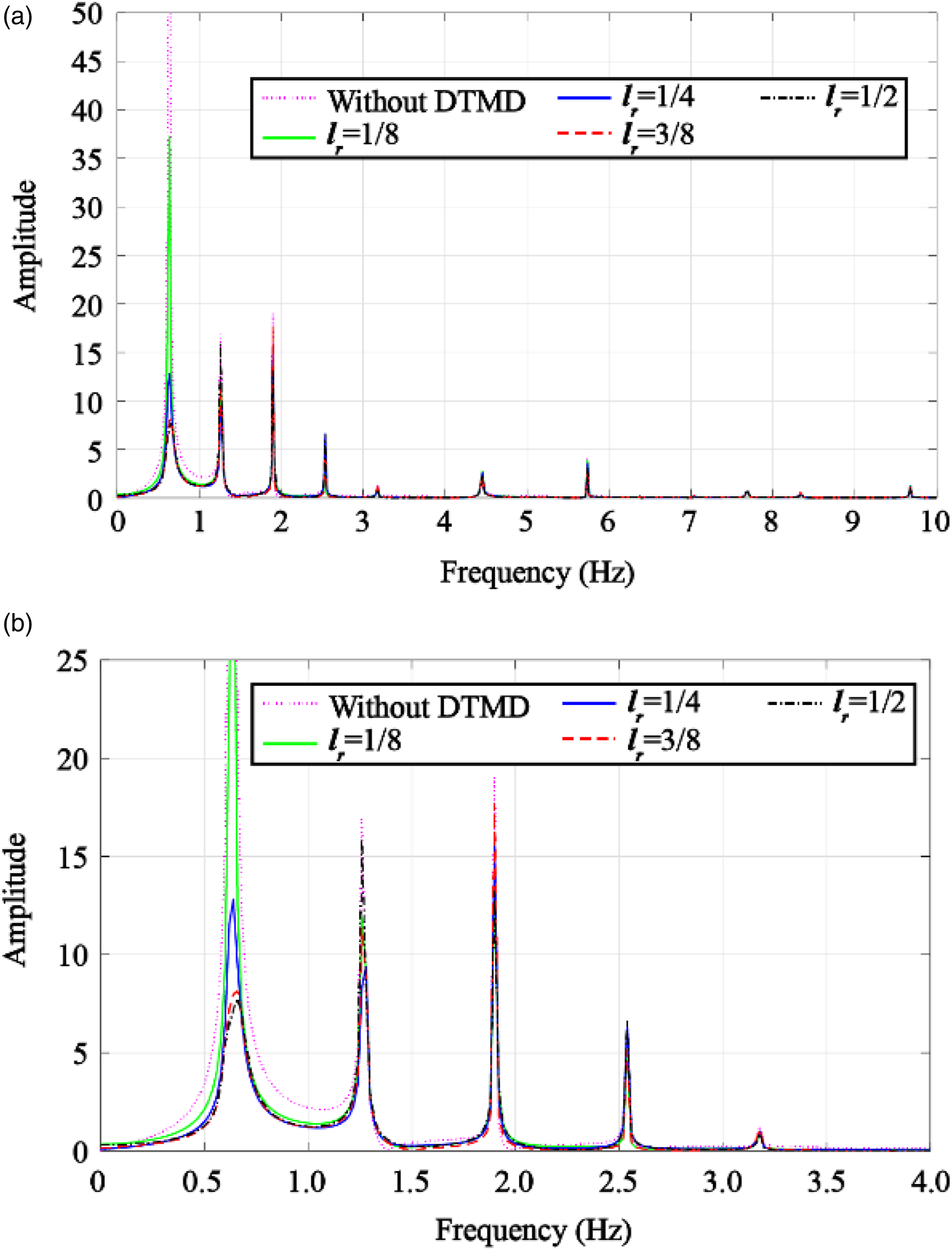
Mass ratio
The mass ratios are designed as 0.002, 0.01, and 0.10 to assess the damper effect of DTMD devices, as shown in Figure 21. Firstly, the control effect is poor when the mass ratio is equal to 0.002. The energy transfer is not obvious under a small mass ratio. Then, the damper effect improves as the mass ratio increases to 0.01. However, as the mass ratio increases to 0.10, the damping effect instead decreases, as shown in Figure 21(a). The results are consistent with the theoretical results shown in Figure 7. C-DTMD systems with different mass ratios. (a) Time domain and (b) frequency domain.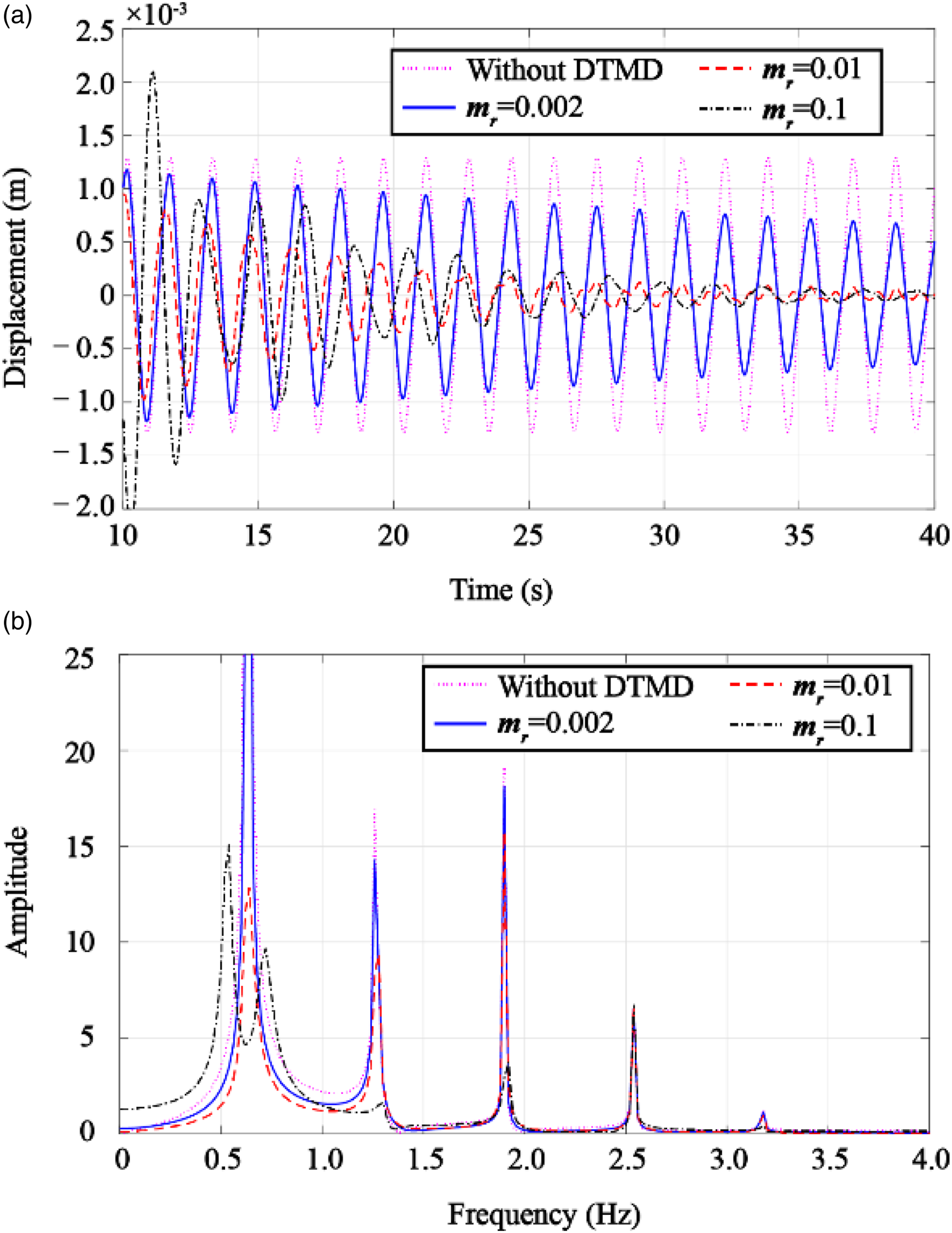
The above results also can be observed in the frequency domain. For the first case, the frequency amplitude of the first-order frequency hardly changes compared with the results without DTMD when the mass ratio is equal to 0.002. Besides, the frequency amplitude further decreases as the mass ratio increases to 0.01. In addition, the modal split is found when the mass ratio is equal to 0.10. The first-order modal shape is divided into two contiguous vibration modals, as shown in Figure 21(b).
Damping ratio
Three cases of damping ratio are studied to verify the results in Section 3.2.3. Based on the theoretical analysis, the excessive or less damping ratios all reduce the vibration reduction effect of the system. Therefore, the damping ratio is designed as 0.02, 0.10, and 0.20. It can be seen in Figure 22(a) that the damping ratio of 0.10 has a better damping effect than in other cases, which is in line with the theoretical results. C-DTMD systems with different damping ratios. (a) Time domain and (b) frequency domain.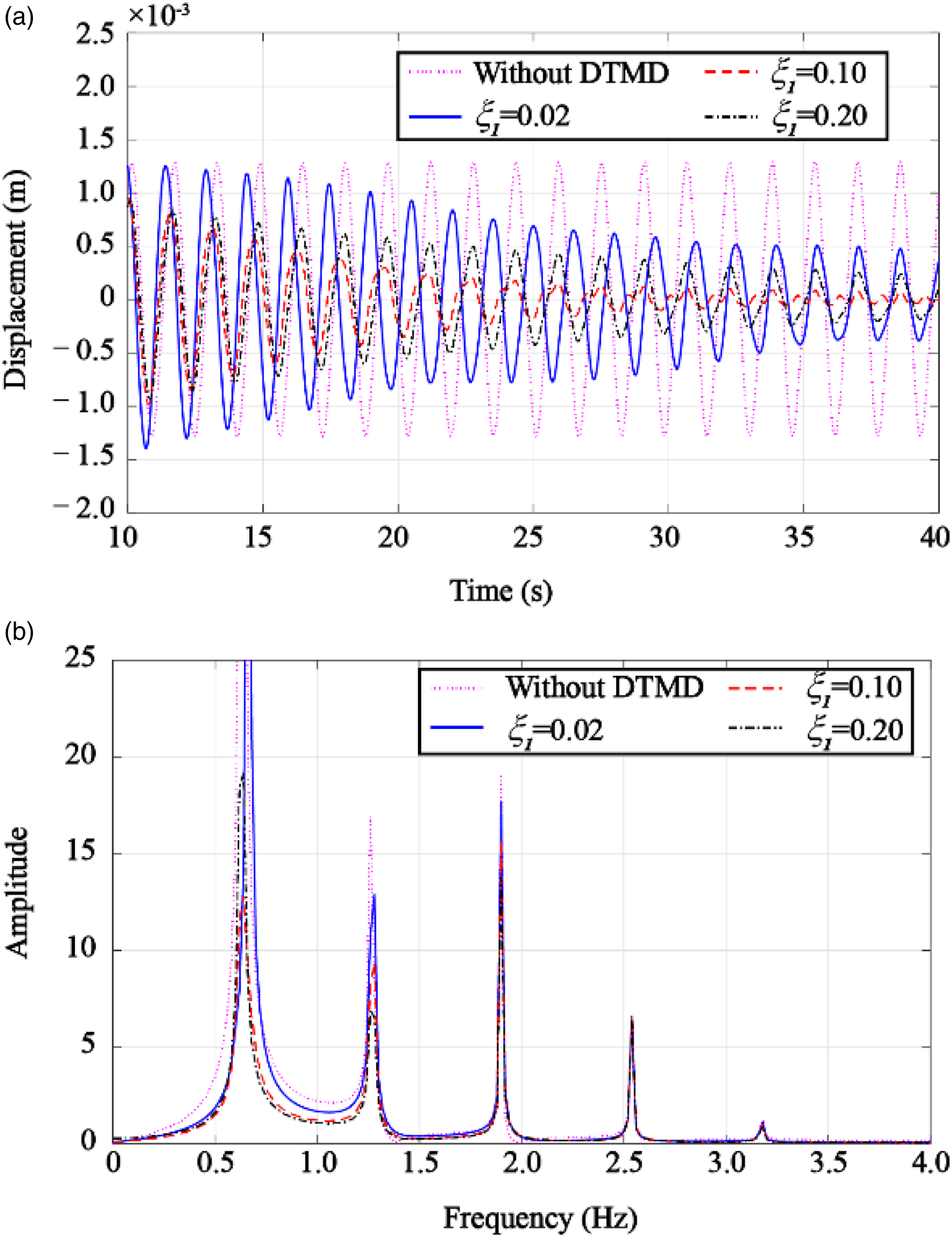
On the other hand, the vibration energy of the first-order modal of the cable first decreases and then increases with the increase of the DTMD damping ratio, as shown in Figure 22(b). Meanwhile, the vibration energy of the second-order modal gradually decreases. The law is basically consistent with that shown in Figure 8.
Frequency ratio
The influence of the frequency ratio is extraordinarily complex. Therefore, only two special cases are selected to discuss their influence on vibration control in this section. Firstly, for Case 1, the frequency ratios of two dampers of DTMD are assumed to be the same or very close, that is, C-DTMD systems with different frequency ratios. (a) Time domain and (b) frequency domain.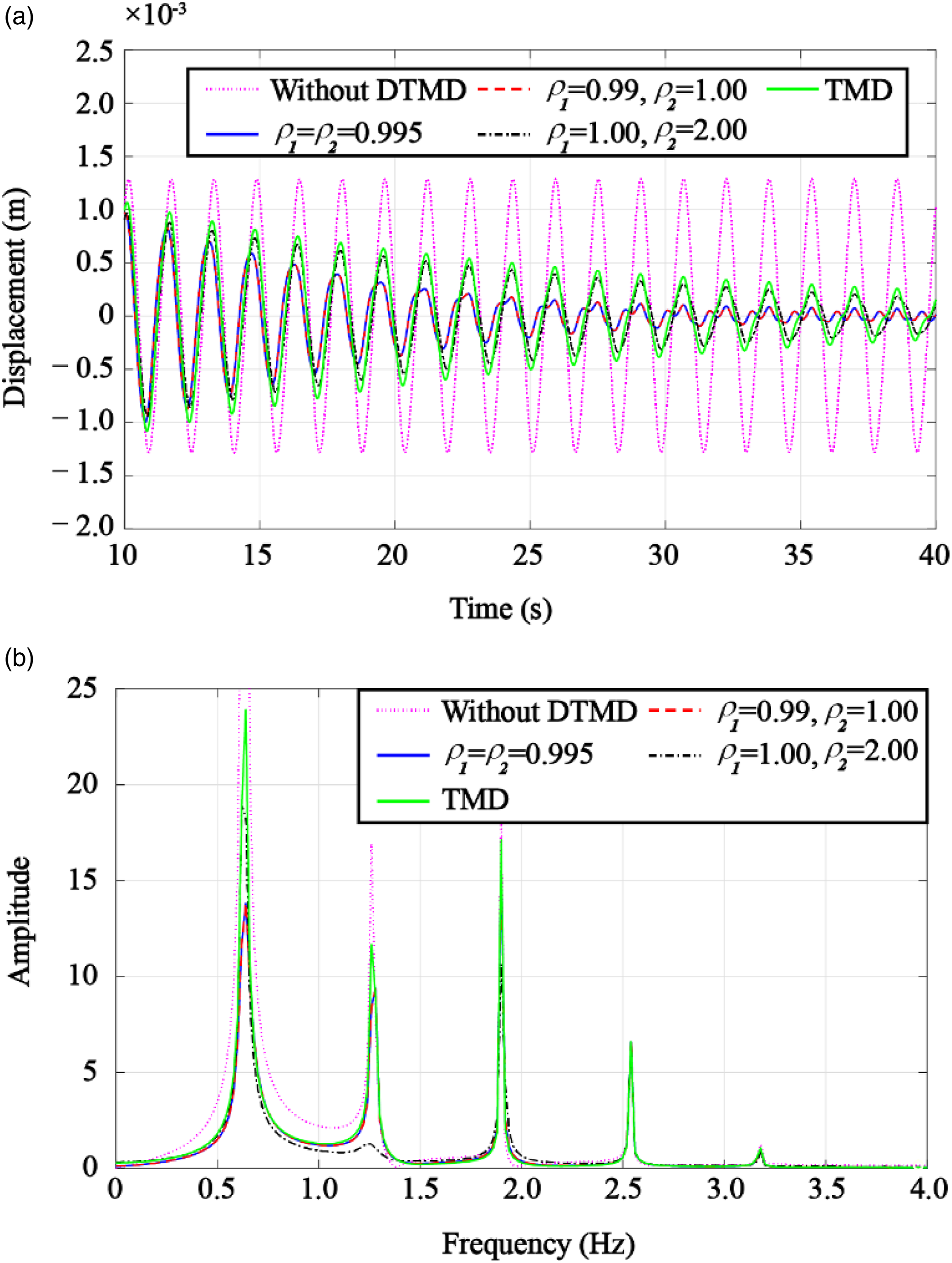
Conclusions
In this paper, a mechanical model of a C-DTMD system is developed by introducing several non-dimensional parameters. The theoretical analysis of the model is conducted to show the modal split and influence factors. The following conclusions are drawn: 1. The frequency variation caused by non-uniform tension is within 2.00% and can be ignored in applications for vertical cables in suspension bridges. The influence of non-uniform tension must be considered for vertical cables with small tension. 2. The modal shapes of C-DTMD systems may split into three homologous modals. The modal split also has an obvious turning point at the installation position of DTMD devices. 3. Several key parameters have an impact on systematic modal damping, including length ratio, mass ratio, damping ratio, and frequency ratio. The recommended installation position is near the middle of the cable. The mass ratio and damping ratio have an optimal value for each order of modal damping. The frequency ratios can be adjusted to control the different modal vibrations of cables.
The multi-parameters optimization design and experimental validation of DTMD devices in practical engineering need to be comprehensively studied in the future.
Footnotes
Declaration of conflicting interests
The author(s) declared no potential conflicts of interest with respect to the research, authorship, and/or publication of this article.
Funding
The author(s) disclosed receipt of the following financial support for the research, authorship, and/or publication of this article: The authors are grateful for the Anhui International Joint Research Center of Data Diagnosis and Smart Maintenance on Bridge Structures [No. 2021AHGHYB04], the University Natural Science Research Project of Anhui Province [No. KJ2021A1098], the Nanjing International Joint Research and Development Program [No. 202112003], the Jiangsu International Joint Research and Development Program [No. BZ2022010], and the Fundamental Research Funds for the Central Universities [No. B220204002].